1
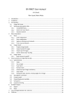
Page 1 sur 1
SERVICE MANUAL
LCD Color Television
42WLG66
Ver. 1
This model is classified as a green product (*1), as indicated by the underlined serial number.
This Service Manual describes replacement parts for the green product. When repairing this
green product, use the part(s) described in this manual and lead-free solder (*2).
For (*1) and (*2), refer to GREEN PRODUCT PROCUREMENT and LEAD-FREE
SOLDER.
© TOSHIBA CORPORATION
file://I:\42WLG66-01\html\!!fcover.html
26/06/10
Page 1 sur 1
IMPORTANT NOTICE
WARNING:
You are requested that you shall not modify or alter the information or data
provided herein without prior written consent by Toshiba. Toshiba shall not be
liable to anybody for any damages, losses, expenses or costs, if any, incurred
in connection with or as a result of such modification or alteration.
THE INFORMATION OR DATA HEREIN SHALL BE PROVIDED "AS IS" WITHOUT
ANY WARRANTY OF ANY KIND, EITHER EXPRESS OR IMPLIED WARRANTY
OF MERCHANTABILITY AND FITNESS FOR A PARTICULAR PURPOSE.
Toshiba shall not be liable for any damages, losses, expenses or costs, if any,
incurred in connection with or as a result of use of any information or data
provided herein.
file://I:\42WLG66-01\html\!!warning.html
26/06/10
Page 1 sur 1
GREEN PRODUCT PROCUREMENT
The EC is actively promoting the WEEE & RoHS Directives that define standards for recycling
and reuse of Waste Electrical and Electronic Equipment and for the Restriction of the use of
certain Hazardous Substances. From July 1, 2006, the RoHS Directive will prohibit any
marketing of new products containing the restricted substances.
Increasing attention is given to issues related to the global environmental. Toshiba Corporation
recognizes environmental protection as a key management tasks, and is doing its utmost to
enhance and improve the quality and scope of its environmental activities. In line with this,
Toshiba proactively promotes Green Procurement, and seeks to purchase and use products, parts
and materials that have low environmental impacts.
Green procurement of parts is not only confined to manufacture. The same green parts used in
manufacture must also be used as replacement parts.
file://I:\42WLG66-01\html\!!green.html
26/06/10
Page 1 sur 1
LEAD-FREE SOLDER
This product is manufactured using lead-free solder as a part of a movement within the consumer
products industry at large to be environmentally responsible. Lead-free solder must be used in
the servicing and repair of this product.
WARNING: This product is manufactured using lead free solder.
DO NOT USE LEAD BASED SOLDER TO REPAIR THIS PRODUCT!
The melting temperature of lead-free solder is higher than that of leaded solder by 86ºF to 104ºF
(30ºC to 40ºC). Use of a soldering iron designed for lead-based solders to repair product made
with lead-free solder may result in damage to the component and or PCB being soldered. Great
care should be made to ensure high-quality soldering when servicing this product especially
when soldering large components, through-hole pins, and on PCBs as the level of heat required
to melt lead-free solder is high.
file://I:\42WLG66-01\html\!!l-f_solder.html
26/06/10
SAFETY INSTRUCTION [LCD] ASIA, EU
Page 1 sur 4
SAFETY INSTRUCTION
WARNING: BEFORE SERVICING THIS CHASSIS, READ THE "SAFETY
PRECAUTION" AND "PRODUCT SAFETY NOTICE" INSTRUCTIONS BELOW.
Safety Precaution
WARNING: SERVICING SHOULD NOT BE ATTEMPTED BY ANYONE
UNFAMILIAR WITH THE NECESSARY PRECAUTIONS ON THIS RECEIVER. THE
FOLLOWING ARE THE NECESSARY PRECAUTIONS TO BE OBSERVED
BEFORE SERVICING THIS CHASSIS.
1. An isolation transformer should be connected in the power line between the receiver and
the AC line before any service is performed on the receiver.
2. Always disconnect the power plug before any disassembling of the product. It may result
in electrical shock.
3. When replacing a chassis in the cabinet, always be certain that all the protective devices
are put back in place, such as nonmetallic control knobs, insulating covers, shields,
isolation resistor-capacitor network, etc.
4. Always keep tools, components of the product, etc away from the children, These items
may cause injury to children.
5. Depending on the model, use an isolation transformer or wear suitable gloves when
servicing with the power on, and disconnect the power plug to avoid electrical shock when
replacing parts. In some cases, alternating current is also impressed in the chassis, so
electrical shock is possible if the chassis is contacted with the power on.
6. Always use the replacement parts specified for the particular model when making repairs.
The parts used in products require special safety characteristics such as inflammability,
file://I:\42WLG66-01\html\!safe[lcd]asia_eu.html
26/06/10
SAFETY INSTRUCTION [LCD] ASIA, EU
Page 2 sur 4
voltage resistance, etc. therefore, use only replacement parts that have these same
characteristics. Use only the specified parts when the mark is indicated in the circuit
diagram or parts list.
7. Parts mounting and routing dressing of wirings should be the same as that used originally.
For safety purposes, insulating materials such as isolation tube or tape are sometimes used
and printed circuit boards are sometimes mounted floating. Also make sure that wirings is
routed and clamped to avoid parts that generate heat and which use high voltage. Always
follow the manufactured wiring routes / dressings.
8. Always ensure that all internal wirings are in accordance before re-assembling the external
casing after a repairing completed. Do not allow internal wiring to be pinched by cabinets,
panels, etc. Any error in reassembly or wiring can result in electrical leakage, flame, etc.,
and may be hazardous.
9. NEVER remodel the product in any way. Remodeling can result in improper operation,
malfunction, or electrical leakage and flame, which may be hazardous.
10. Touch current check. (After completing the work, measure touch current to prevent an
electric shock.)
z
z
Plug the AC cord directly into the AC outlet. Do NOT use an isolation transformer for
this check.
Connect a measuring network for touch currents between each exposed metallic part on
the set and a good earth ground such as a water pipe.
Annex D
(normative)
Measuring network for TOUCH CURRENTS
file://I:\42WLG66-01\html\!safe[lcd]asia_eu.html
26/06/10
SAFETY INSTRUCTION [LCD] ASIA, EU
Page 3 sur 4
Resistance values in orms (Ω).
V: Voltmeter or oscilloscope
(r.m.s. or peak reading)
Input resistance :
1 MΩ
Input capacitance :
200 pF
Frequency range : 15 Hz to 1 MHz and d.c. respectively
Note: Appropriate measures should be taken to obtain the correct value in case of non
sinusoidal waveforms.
The measuring instrument is calibrated by comparing the frequency factor of
with the solid
line in figure F.2 of IEC 60990 at various frequencies. A calibration curve is constructed
showing the deviation of
from the ideal curve as a function of frequency.
TOUCH CURRENT =
z
/500 (peak value).
The potential at any point (TOUCH CURRENT) expressed as voltage
not exceed the following value:
and
does
The part or contact of a TERMINAL is not HAZARDOUS LIVE if:
a) The open-circuit voltage should not exceed 35 V (peak) a.c. or 60 V d.c. or, if a) is not met.
b) The measurement of the TOUCH CURRENT shall be carried out in accordance with IEC
60990, with the measuring network described in Annex D of this standard.
The TOUCH CURRENT expressed as voltages
and
values:
- for a.c. :
= 35 V (peak) and
= 0.35 V (peak);
- for d.c. :
= 1.0 V
= 0.35 V (peak) for a.c. and
Note: The limit values of
values 0.7 mA (peak) a.c. and 2.0 mA d.c.
file://I:\42WLG66-01\html\!safe[lcd]asia_eu.html
, does not exceed the following
= 1.0 V for d.c. correspond to the
26/06/10
SAFETY INSTRUCTION [LCD] ASIA, EU
Page 4 sur 4
Product Safety Notice
Many electrical and mechanical parts in this chassis have special safety-related characteristics.
These characteristics are often passed unnoticed by a visual inspection and the protection
afforded by them cannot necessarily be obtained by using replacement components rated for
higher voltage, wattage, etc. Replacement parts which have these special safety characteristics
are identified in this manual and its supplements; electrical components having such features are
identified by the international hazard symbols on the schematic diagram and the parts list.
Before replacing any of these components, read the parts list in this manual carefully. The use of
substitute replacement parts which do not have the same safety characteristics as specified in the
parts list may create electrical shock, fire, or other hazards.
file://I:\42WLG66-01\html\!safe[lcd]asia_eu.html
26/06/10
Handling the LCD Module
Page 1 sur 4
SAFETY INSTRUCTION
Handling the LCD Module
Safety Precaution
In the event that the screen is damaged or the liquid crystal (fluid) leaks, do not breathe in or
drink this fluid.
Also, never touch this fluid. Such actions could cause toxicity or skin irritation. If this fluid
should enter the mouth, rinse the mouth thoroughly with water. If the fluid should contact the
skin or clothing, wipe off with alcohol, etc., and rinse thoroughly with water. If the fluid should
enter the eyes, immediately rinse the eyes thoroughly with running water.
Precautions for Handling the LCD Module
CAUTION: The metal edges of the LCD module are sharp, handle it with care.
The LCD module can easily be damaged during disassembly or reassembly; therefore, always
observe the following precautions when handling the module.
1. When attaching the LCD module to the LCD cover, position it appropriately and fasten at
the position where the display can be viewed most conveniently.
2. Carefully align the holes at all four corners of the LCD module with the corresponding
holes in the LCD cover and fasten with screws. Do not strongly push on the module
because any impact can adversely affect the performance. Also use caution when handling
the polarized screen because it can easily be damaged.
file://I:\42WLG66-01\html\!handling_lcd.html
26/06/10
Handling the LCD Module
Page 2 sur 4
3. If the panel surface becomes soiled, wipe with cotton or a soft cloth. If this does not
remove the soiling, breathe on the surface and then wipe again.
If the panel surface is extremely solied, use a CRT cleaner as a cleaner. Wipe off the panel
surface by drop the cleaner on the cloth. Do not drop the cleaner on the panel. Pay
attention not to scratch the panel surface.
4. Leaving water or other fluids on the panel screen for an extended period of time can result
in discoloration or stripes. Immediately remove any type of fluid from the screen.
5. Glass is used in the panel, so do not drop or strike with hard objects. Such actions can
damage the panel.
file://I:\42WLG66-01\html\!handling_lcd.html
26/06/10
Handling the LCD Module
Page 3 sur 4
6. CMOS-LSI circuitry is used in the LCD module, so avoid damage due to static electricity.
When handling the module, use a wrist ground or anchor ground.
7. Do not expose the LCD module to direct sunlight or strong ultraviolet rays for an extended
period of time.
8. Do not store the LCD module below the temperature conditions described in the
specifications. Failure to do so could result in freezing of the liquid crystal due to cold air
or loss of resilience or other damage.
9. Do not disassemble the LCD module. Such actions could result in improper operation.
file://I:\42WLG66-01\html\!handling_lcd.html
26/06/10
Handling the LCD Module
Page 4 sur 4
10. When transporting the LCD module, do not use packing containing epoxy resin (amine) or
silicon resin (alcohol or oxim). The gas generated by these materials can cause loss of
polarity.
file://I:\42WLG66-01\html\!handling_lcd.html
26/06/10
LC D -P h3R 32W LT 66/32W L66C /32L66X *
UP O01A
W ER P ow er
EG U LA
TO W
R -B
U R01B
LO
AV
U 02A
A V TER M
B -B
23P
B -B
9P
B -B
13P
B 002 D igitalU nit
? ? D IG ITA L U N IT
B -B
13P
SUIG03A
N A L S IG N A L
C ortez P lus
B -B
23P
B -B
50P
P C M C IA
C ARD
F-A V
LED
U 02B
U 02C
K EY
U 02D
U 02F
AV BOARD
SIGNAL BOARD
PANEL
DDR RAM
RF
FLI8538
TIF
CORTEZ Plus
VBI Data
Processor
N on
PANEL I/F
Input
Terminal
(Audio)
Analog
Front
End
(16port)
CVBS(L/R)
S-VIDEO(L/R)
YCbCr(L/R)
Standby
uCON
DCDi
MADi
Scaling
Video
Decoder
BEP
MUX
656
I2C
PC_IN(L/R)
OSD
2nd
Channel
Process
I2C
Digital
Input A
SW
EEPROM
Digital
Input B
IR I/F
MTS+
APRO
MSP
AMP
DAC
LVD
S
Microprocessor
GPI
AD
YCbCr 16bit
I2C
FLASH ROM
HP_AMP
Cortez
Regulator
Sound AMP
Bt 601 8Bit
H D,VD,CLK
Input
Terminal
(Video)
CVBS
S-VIDEO
YCbCr
PC IN
PLL
RE Q
HDMI
U ART
VOC
SPEAKER
+Low B
POWER BOARD
Headphone
HDMI
AC INPUT&
Power
Page 1 sur 2
SCHEMATIC DIAGRAM
Precaution
WARNING: BEFORE SERVICING THIS CHASSIS, READ THE "X-RAY
RADIATION PRECAUTION" FOR DIRECT VIEW CTV ONLY, "SAFETY
PRECAUTION" AND "PRODUCT SAFETY NOTICE" OF THIS MANUAL.
CAUTION: The international hazard symbols " " in the schematic diagram and
the parts list designate components which have special characteristics
important for safety and
should be replaced only with types identical to those in the original circuit or
specified in the parts list.
The mounting position of replacements is to be identical with originals.
Before replacing any of these components, read carefully the SAFETY
PRECAUTION and PRODUCT SAFETY NOTICE.
Do not degrade the safety of the receiver through improper servicing.
Note:
1. RESISTOR
Resistance is shown in ohm [K=1,000, M=1,000,000]. All resistors are 1/6 W and 5 %
tolerance carbon resistor, unless otherwise noted as the following marks.
1/2R
1/2S
1RF
10 W
K
G
F
:
:
:
:
:
:
:
Metal or Metal oxide of 1/2 watt
Carbon composition of 1/2 watt
Fuse resistor of 1 watt
Cement of 10 watt
±10 %
±2 %
±1 %
2. CAPACITOR
Unless otherwise noted in schematic, all capacitor values less than 1 are expressed in µF,
and the values more than 1 in pF.
file://I:\42WLG66-01\html\c_precaution.html
26/06/10
Page 2 sur 2
All capacitors are ceramic 50 V, unless otherwise noted as the following marks.
= Electrolytic capacitor
= Mylar capacitor
3. The parts indicated with " " have special characteristics, and should be replaced with
identical parts only.
4. Voltages read with DIGITAL MULTI-METER from point indicated to chassis ground,
using a color bar signal with all controls at normal, line voltage at nominal AC volts.
5. Waveforms are taken receiving color bar signal with enough sensitivity.
6. Voltage reading shown are nominal values and may vary ±20 % except H.V.
file://I:\42WLG66-01\html\c_precaution.html
26/06/10