1
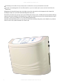
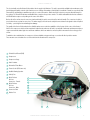
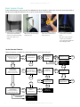
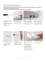
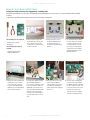
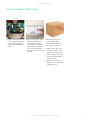
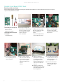
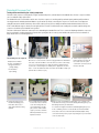
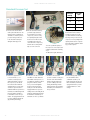
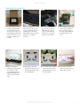
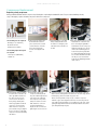
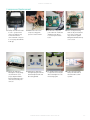
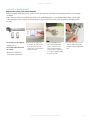
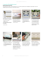
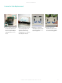
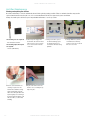
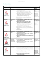
Service Manual
DIRECTHEALTHCARESERVICES.CO.UK
DYNA-FORM AIR PRO-PLUS
2
DIRECTHEALTHCARESERVICES.CO.UK
SERVICE MANUAL
Definition of Symbols Used
Caution: Warning of possible hazard to system, patient or staff.
Warning of possible electrical hazard.
Important operational information.
Contents
Control Unit�������������������������������������������������������������������������������������������������������������������������������������������������������������������������4
Internal Descriptions������������������������������������������������������������������������������������������������������������������������������������������������������������5
Basic System Checks�����������������������������������������������������������������������������������������������������������������������������������������������������������7
Fuse Check and Replacement����������������������������������������������������������������������������������������������������������������������������������������������8
Printed Circuit Board (PCB) Check�����������������������������������������������������������������������������������������������������������������������������������������9
Printed Circuit Board (PCB) Replacement .............................................................................................................................10
Standard Pressure Test ......................................................................................................................................................11
Compressor Replacement ..................................................................................................................................................13
Synchronous Motor Replacement . ......................................................................................................................................15
Connector Replacement .....................................................................................................................................................18
Connector Plate Replacement .............................................................................................................................................19
Air Filter Maintenance ........................................................................................................................................................21
Rubber Feet Replacement ..................................................................................................................................................22
Hanging Hook Replacement . ..............................................................................................................................................24
Troubleshooting ................................................................................................................................................................26
Safety . .............................................................................................................................................................................29
Care & Cleaning ................................................................................................................................................................30
DIRECTHEALTHCARESERVICES.CO.UK
3
DYNA-FORM AIR PRO-PLUS
The following section outlines the steps and procedures to follow if there is a suspected fault in the Control Unit.
If a repair seems unmanageable or the issue falls outside the scope of serviceable repairs, please return the Control Unit to the
Manufacturer.
Malfunction of the Control Unit may be due to the failure of one of the replaceable electrical components of the Control Unit,
including the compressor, print circuit board and timing motor rotary valve.
Alternatively, a lack or loss of system pressure can be attributed to a variety of causes, including an incorrectly attached CPR Tag;
a loosely connected or leaking Air Cell; leaking Air Hose; or faulty fuse. Insufficient system pressure is identified when the Visible
LED flashes, and the corresponding Pressure Setting Warning signals display.
Should the Control Unit fail to operate, or system pressure fail to reach normal operating status, please follow the steps below to
isolate the cause of the problem and make the relevant repair.
4
DIRECTHEALTHCARESERVICES.CO.UK
SERVICE MANUAL
The electronically controlled Control Unit provides the air supply to the Mattress. The unit is operated by a digital touch membrane on the
front display panel which controls eight comfort pressure settings; Alternating or Static Mode for treatment or transfers respectively; Max
Firm mode for rapid inflation to maximum pressure to create a firm surface; and Control Unit Lockout to prevent accidental changes to
the settings. The Visual LED indicator and Audible Mute completes the operator controls. The visible and audible function has a number
of LED indication sequences depending on the cause of the failure.
On the side of the unit are two air connectors (male and female) for quick connection of the two hole handle. The connectors include a
press button release system for ease of use. The mains supply to the unit can be easily disconnected and is designed to detach if pulled
too firmly – protecting the internal wiring from damage.
The quality of the Control Unit underpins the reliability and pressure reduction capabilities of the System. At the centre of the Control
Unit lies the compressor, which runs at a rapid and continuous rate whenever the unit is operational. Continuous rapid movement places
compressor materials under high stress and heat conditions, which can make the unit susceptible to wear and tear over a long period
of time.
To minimise noise and vibration, the compressor is housed within a strong metal cage, secured on all sides by rubber mounts.
These mounts serve to insulate the rest of the unit from the vibration of the compressor.
1
Printed Circuit Board (PCB)
2
Compressor
3
Compressor Cage
4
Static Actuator
5
Alternation Timer Motor
6
Power Socket (IEC Connector)
7
Audible Warning Speaker
8
Safety Fuse
9
Quick Release
Air Hose
Connector - Female
3
2
1
Quick Release
Air Hose
Connector - Male
10
11
Connector Plate
8
12
Rubber Feet
10
9
7
11
11
DIRECTHEALTHCARESERVICES.CO.UK
5
4
5
DYNA-FORM AIR PRO-PLUS
Basic System Checks
Before commencing any service procedure, the following basic checks should be completed to ensure that system fault or failure is
not due to an oversight on behalf of the user. Set up the system and check the following:
2 C heck the Air Hoses are securely
attached to the Control Unit (they
should ‘click’ on).
1 E nsure all power cords and leads
are firmly attached and that the
system is connected to a working
power source (with correct
voltage).
3 Remove the Mattress Top Cover
and check the deflation valve is
firmly connected.
4 C heck each Air Cell is firmly
connected to the internal air
hose/s.
Once these simple checks are
complete, proceed with the
service and repair as outlined in
the following procedures.
Service Procedure Flowchart
Follow the flowchart to establish the recommended steps for system check and repair.
Control Unit is inoperable
(Display Panel fails to activate
when unit is connected
to a power source)
YES
NO
Fuse Check and
Replacement
STILL
INOPERABLE
fails to reach operation
pressure or loses pressure
Basic System Checks
YES
(check power &
power cords; Air Hose
Attachments; CPR Tag;
Air Cell attachment)
STILL LOW
PRESSURE
FIXED
the motor is ‘grinding’ or
making an unusual sound
OTHER PROBLEM
Standard
Pressure Test
PRESSURE
NOT
OK
FIXED
Control Unit is
operational but
Compressor
Replacement
NOT
FIXED
YES
Synchronous
Motor
Replacement
PCB Replacement
FIXED
Return to
Manufacturer
PRESSURE
OK
FIXED
NO
CONFIRMS
FAULTY PCB
CHECK FAILS
FIXED
Control Unit is
operational but
6
Printed Circuit
Board (PCB)
Check
NOT FIXED
Return to
Manufacturer
Return to
Manufacturer
DIRECTHEALTHCARESERVICES.CO.UK
PRESSURE
OK
Air Leak Test
DEFLATING
Air Cell
Replacement
FIXED
SERVICE MANUAL
Fuse Check and Replacement
Testing fuse for damage and replacing a blown fuse
Control Unit failure may be the result of a blown fuse. Always check the fuse before opening the unit and performing
any other internal component test procedures.
Note: When changing the replaceable fuse, use same rating fuse only (T1AL/250V).
The following tools are required:
• Flat Head Screwdriver
The following replacement parts
are required:
1 S witch off power supply to the
Control Unit and remove the
power cord from the electrical
socket in the base of the unit.
2 Using a level surface, place the
Control Unit on its base, with easy
access to the black round fuse
cap located on the side of the unit
(closest to the connectors).
3 Insert a small screwdriver into the
groove on the fuse cap and turn
counterclockwise in the direction
of the arrow (quarter turn) to
remove the fuse plug and single
fuse.
5 Insert a new fuse (or the
undamaged fuse) into the plug.
Push against the force of the
spring and turn clockwise with
the screwdriver (quarter turn).
6 Reconnect the power cord to the
Control Unit and switch on power
supply.
If Control Unit still fails to operate,
the problem may be due to a
faulty circuit board. Proceed
to Printed Circuit Board Check
procedure. If the unit switches
on but fuse “blows” again, repeat
the steps to replace the damaged
fuse but do not reconnect power
as damage may be due to a faulty
compressor. Proceed to Standard
Pressure Test procedure.
• 250V fuse (M8260138)
4 V isually inspect the fuse – check
if the metal filament inside the
fuse cylinder is disconnected
or snapped – and discard
if damaged (or re-insert if
undamaged).
DIRECTHEALTHCARESERVICES.CO.UK
7
DYNA-FORM AIR PRO-PLUS
Printed Circuit Board (PCB) Check
Testing for a faulty circuit board by ‘piggybacking’ a working spare
If the Control Unit still fails to operate after checking and replacing a damaged fuse, the next step is to test the Printed Circuit Board (PCB)
for failure.
To determine if the PCB has failed, always test the Control Unit using a working spare.
The following tools are required:
• Phillips Head Screwdriver
• Wire Clippers
The following spare parts are
required:
1 S witch off power supply to the
Control Unit, disconnect the Air
Hoses and remove the power
cord from the electrical socket in
the base of the unit.
2 Using a soft cloth to protect
the unit from damage, place
the Control Unit on a level
work surface with base facing
upwards.
3 Use a Phillips Head Screwdriver
to remove the four screws that
secure the housing. Place the
screws and washers in a safe
place (such as small container
or jar) to prevent loss. Hold the
unit firmly and turn it over, face
upwards on its base.
5 Disconnect the four electronic
power leads by cutting the
cable ties that secure the leads
to the PCB. Carefully pull the
plastic casing (not the wiring) to
disconnect.
6 Disconnect the remaining three
connections from the PCB (two
flat digital leads and one air tube).
Be sure to note the location of all
seven connections on the circuit
board for easy replacement.
Leave the disconnected PCB in
the Control Unit during testing.
• 1 x PCB (in known working
condition) (M8260143)
4 Gently loosen the top and bottom
housing. Once loose, hold the
power socket (IEC connector)
to prevent from catching while
lifting the top cover and leaning it
back on your work surface.
8
B e careful not to drag the internal
wires and tubing during this
process. Before continuing, ensure
no electrical leads are stretched
and that all electrical connectors
on the Printed Circuit Board (PCB)
are firmly connected. You may
need to prop the top housing case
to prevent strain on the electrical
cords.
DIRECTHEALTHCARESERVICES.CO.UK
SERVICE MANUAL
Printed Circuit Board (PCB) Check
7 Take the working spare PCB and
reconnect all seven leads into the
corresponding connectors (four
electronic leads; two digital; one
air hose).
8 R econnect mains power, switch
on the Control Unit and check
the Display Panel. If the unit
now operates, the internal PCB
has failed and needs replacing.
Proceed to the Printed Circuit
Board Replacement procedure for
next steps.
If the Control Unit still does not
operate, the unit needs to be
returned to the Manufacturer for
further repair or replacement.
a S witch off power supply to the
Control Unit, remove the spare
PCB and reconnect the internal
PCB (reconnect the seven power
leads to the circuit board) before
closing the housing.
b R eturn the Control Unit to the
Manufacturer in accordance with
standard procedures.
DIRECTHEALTHCARESERVICES.CO.UK
9
DYNA-FORM AIR PRO-PLUS
Printed Circuit Board (PCB) Check
Replacing a faulty circuit board
Having established a fault with the PCB by following the Printed Circuit Board Check procedure detailed previously (steps 1 through 7),
replace the faulty PCB with a new PCB.
The following tools are required:
• Needle Nosed Pliers
• Phillips Head Screwdriver
The following replacement parts
are required:
8 S witch off power supply to the
Control Unit before disconnecting
the spare ‘test’ PCB. Disconnect
all seven leads while noting the
location of each lead
on the circuit board.
9 Using Needle Nosed Pliers, unclip
the PCB from the top housing.
Note the orientation of the PCB
before removing it from
the unit.
Dispose of the faulty PCB in an
environmentally safe manner.
10 U npack the replacement PCB.
Align the circuit board against
the four holes and carefully
reconnect the clips by pressing
firmly into place.
12 B efore closing the housing,
make sure all power leads and
hoses are free from the side
edges. Ensure the regulator
tubing will not kink when the
top cover
is closed.
13 A lign the top and bottom
housing before slowly pushing
closed. Ensure the seal is
properly aligned around the
housing, including the air hose
connectors, fuses and power
connector.
15 U se a Phillips Head Screwdriver
to replace the four screws plus
washers and tighten to secure
the housing together.
• 1 x PCB (M8260143)
11 R econnect all seven leads into
the corresponding connectors
on the circuit board.
14 H olding the top and bottom
housing firmly together, turn the
Control Unit upside down, with
base facing upwards.
10
DIRECTHEALTHCARESERVICES.CO.UK
16 C onnect the Control Unit to
mains power and switch on
the Control Unit to confirm
operation.
SERVICE MANUAL
Standard Pressure Test
Testing airflow and checking for a faulty compressor
The Control Unit compressor is designed for long life, and backed by a two-year warranty from the Manufacturer, however compressor failure
can occur and will require replacement.
The Standard Pressure Test should be carried out to check the compressor is working at full operational capacity and that sufficient airflow
is being generated to maintain maximum Mattress specifications. By directly connecting the compressor to the Pressure Test Equipment
(Sphygmomanometer and Air Flow Meter), this test will confirm system pressure readings at maximum and minimum airflow (in free flow
mode or with different degrees of back pressure applied). If the Pressure Test fails and pressure readings do not match required settings, the
compressor should be replaced and the test repeated.
The Control Unit must be allowed to “warm up” before undertaking the Standard Pressure Test, to ensure the diaphragm inside the compressor
has loosened and is operating at maximum capacity. After opening the unit, reconnect power and allow the system to run for a minimum of
thirty minutes before commencing this test.
The following tools are required:
• Phillips Head Screwdriver
• Pressure Test Equipment
> Sphygmomanometer
(mmHg reading)
> Air Flow Meter
(Lpm reading)
2 U sing a soft cloth to protect
the unit from damage, place
the Control Unit on a level
work surface with base facing
upwards.
Pressure Test Equipment Set Up
One air hose is connected to the rear of the Sphygmomanometer and another
to the base of the Air Flow Meter. These two air hoses are then connected by
a ‘Y’ piece to form a single air hose outlet. Check all hose attachments are
secure before commencing the test. Initially set the equipment to free flow
mode – ensure the airflow valve at the front of the Air Flow Meter is fully open
(turn the valve clockwise to open).
3 U se a Phillips Head Screwdriver
to remove the four screws that
secure the housing. Place the
screws and washers in a safe
place (such as small container
or jar) to prevent loss. Hold the
unit firmly and turn it over, face
upwards on its base.
1 S witch off power supply to the
Control Unit, disconnect the Air
Hoses and remove the power
cord from the electrical socket in
the base of the unit.
4 G
ently loosen the top and bottom housing. Once loose, hold the power
socket (IEC connector) to prevent from catching while lifting the top cover
and leaning it back on your work surface.
Be careful not to drag the internal wires and tubing during this process.
Before continuing, ensure no electrical leads are stretched and that
all electrical connectors on the Printed Circuit Board (PCB) are firmly
connected. You may need to prop the top housing case to prevent strain
on the electrical cords.
DIRECTHEALTHCARESERVICES.CO.UK
11
DYNA-FORM AIR PRO-PLUS
Standard Pressure Test
5 R econnect the Control Unit to
mains power and switch on. The
unit must run for a minimum of
30 minutes to “warm up” before
pressure testing commences.
Leave the unit in a safe place
during the warm up period.
a Ensure the equipment is set
to ‘free flow mode’ (i.e. no
resistance or back pressure
against the full flow of air from
the compressor). The valve at
the front of the Air Flow Meter
should be fully open. If not, turn
clockwise to open the valve to
maximum. With the system in free
flow mode, the ball bearing inside
the Air Flow Meter should rise
to a minimum of 4.5+ litres per
minute. The Sphygmomanometer
pressure reading should be low
(approximately 10 mmHg).
12
6 A fter the 30 minute “warm up”
period has elapsed, detach
the internal air hose from the
compressor (some force may
be required) and replace with
the air hose from the Pressure
Test Equipment (for directly
connection to the compressor).
Push the air hose firmly until it
fully covers the connector.
b S lowly close the valve on the Air
Flow Meter to reduce airflow air
and simulate ‘back pressure’ (i.e.
to emulate the weight of a patient
lying on the mattress, which
forces pressure back against
the flow of air from the unit).
Slowly close the valve until the
Sphygmomanometer pressure
reading reaches 30 mmHg. At 30
mmHg, the ball bearing inside the
Air Flow Meter should drop to a
minimum of 3+ litres per minute.
To check operational capacity of
the compressor, test each pressure
setting as outlined in the following
steps.
The table above right, summarises
c Continue to increase back
pressure resistance. Slowly close
the valve on the Air Flow Meter
until the Sphygmomanometer
pressure reading reaches 60
mmHg. At 60 mmHg, the ball
bearing inside the Air Flow Meter
should drop to a minimum of 2+
litres per minute.
DIRECTHEALTHCARESERVICES.CO.UK
Base
Pressure
mmHg
Air Flow
Lpm
>10
4.5+
30
3+
60
2+
120>
0
the expected pressure and air
flow measurements. If air flow
measurements fail to meet the
specified minimum levels during
any stage of the pressure test, the
compressor is not operating at full
capacity and needs to be replaced.
Remember that a 30 minute “warm
up” period is required.. d Finish testing by fully closing
the Air Flow Meter valve
(maximum resistance). The
ball bearing inside the Air Flow
Meter should drop to 0 and the
Sphygmomanometer pressure
reading should rise to 120+
mmHg.
SERVICE MANUAL
Standard Pressure Test
e If air flow measurements fail to
meet the specified minimum
levels during any stage of the
pressure test, the compressor is
not operating at full capacity and
needs to be replaced. Proceed
to Compressor Replacement
procedure.
If all pressure and air flow
measurements met the expected
levels, the problem may be due to
a leaking Air Cell or other defect
with the Mattress. Close the Control
Unit and proceed to Mattress
procedures.
7 To close the Control Unit, first
disconnect the Pressure Test
Equipment air hose from the
compressor and reattach the
internal air hose, using gentle
pressure to ensure a firm fit.
8 Before closing the housing, make
sure all power leads and hoses
are free from the side edges.
Ensure the regulator tubing will
not kink when the top cover is
closed.
9 A lign the top and bottom
housing before slowly pushing
closed. Ensure the seal is
properly aligned around the
housing, including the air hose
connectors, fuses and power
socket.
10 H olding the top and bottom
housing firmly together, turn the
Control Unit upside down, with
base facing upwards.
11 U se a Phillips Head Screwdriver
to replace the four screws plus
washers and tighten to secure
the housing together.
12 C onnect the Control Unit to
mains power and switch on the
unit to confirm operation.
DIRECTHEALTHCARESERVICES.CO.UK
13
DYNA-FORM AIR PRO-PLUS
Compressor Replacement
Replacing a faulty compressor
Having established a fault with the compressor by following the completing the Standard Pressure Test procedure detailed previously
(steps 1 through 6), replace the faulty compressor with a new compressor.
The following tools are required:
• Wire Clippers (or sharp knife)
• Needle Nosed Pliers
• Phillips Head Screwdriver
The following replacement parts
are required:
7 S witch off power supply to the
Control Unit and remove the
power cord from the electrical
socket in the base of the unit
before disconnecting the
Pressure Test Equipment air
hose.
8 Using Wire Clippers (or a sharp
knife) carefully cut and remove
the cable tie securing the power
leads between the two halves of
the unit.
• 1 x Compressor (M8260139)
• 1 x Cable Tie
10 U sing a Phillips Head Screwdriver 11 Unpack the replacement
loosen the two screws at the end
compressor. Carefully thread
of the cage furthest from the air
the power lead through the base
hose inlets. Then remove the
of the cage before sliding the
screws closest to the air hose
new compressor into position
inlets, placing carefully aside.
(with power lead closest to the
Tilt the cage upwards to slide the
PCB, and air hose connector
compressor over the housing
positioned towards base).
struts. Ensure the compressor
Replace the two screws before
power lead does not get caught in
tightening the loosened screws.
the process. Dispose of the faulty
compressor in an environmentally
safe manner.
14
9 Check the internal compressor power
lead and air hose is disconnected
before removing the eight rubber
mounts that secure the compressor
within the metal cage. It is easier to
extract each mount using a pair of
needle nosed pliers to gently twist
free rather than pulling directly with
force. If rubber mounts break, make
sure all pieces are removed from
inside the unit. Undamaged mounts
can be reused.
12 S ecure the compressor to the metal cage by connecting the eight new
rubber mounts, starting with four mounts on one side of the cage (bottom
followed by top), then four mounts on opposite side.
When connecting mounts, it helps to prop or hold the compressor
within the cage to better align the mount holes. Insert the tapered end
of the rubber mount through the corresponding hole in the cage, gently
pushing through until the mount can be twisted around the nose of the
pliers and pulled firmly into place
DIRECTHEALTHCARESERVICES.CO.UK
SERVICE MANUAL
Compressor Replacement
13 V isually check that each mount
is secure – gently move the
compressor within the cage
to ensure all mounts are
connected and the compressor
is correctly suspended with the
metal cage.
14 R eattach the air hose to the
compressor, using gentle
pressure to ensure a firm fit.
15 R econnect the compressor
power lead to the circuit board
and attach a new cable tie
to secure all power leads as
before.
16 B efore closing the housing,
make sure all power leads and
hoses are free from the side
edges. Ensure the regulator
tubing will not kink when the top
cover is closed.
17 A lign the top and bottom
housing before slowly pushing
closed. Ensure the seal is
properly aligned around the
housing, including the air hose
connectors, fuses and power
connector.
18 H olding the top and bottom
housing firmly together, turn the
Control Unit upside down, with
base facing upwards.
19 U se a Phillips Head Screwdriver
to replace the four screws plus
washers and tighten to secure
the housing together.
20 Connect the Control Unit to
mains power and switch on
the Control Unit to confirm
operation.
DIRECTHEALTHCARESERVICES.CO.UK
15
DYNA-FORM AIR PRO-PLUS
Synchronous Motor Replacement
Replacing a faulty synchronous motor
The synchronous motor runs the rotovalve that operates the timing mechanism for the alternation cycle. If the rotovalve becomes worn or
damaged it no longer spins smoothly and the unit will emit a distinct ‘grinding’ noise.
If you hear an uncharacteristic noise from the motor when the Control Unit is switched on, the synchronous motor needs to be replaced.
The following tools are required:
• Phillips Head Screwdriver
• Wire Clippers (or sharp knife)
• Flat Head Screwdriver (small)
• 7/32 Inch Socket Wrench
1 S witch off power supply to the
Control Unit, disconnect the Air
Hoses and remove the power
cord from the electrical socket in
the base of the unit.
2 Using a soft cloth to protect
the unit from damage, place
the Control Unit on a level
work surface with base facing
upwards.
3 U se a Phillips Head Screwdriver
to remove the four screws that
secure the housing. Place the
screws and washers in a safe
place (such as small container
or jar) to prevent loss. Hold the
unit firmly and turn it over, face
upwards on its base.
6 Trace the power lead running
from underneath the synchronous
motor to its connection on the
circuit board. Disconnect this lead
from the circuit board by carefully
pulling the plastic casing (not the
wiring) and gently remove the lead
from under the compressor cage
and leave it free.
7 U sing thumb and forefinger,
push down firmly on the plastic
rotovalve casing to release tension
while removing the split pin – a
deal of downward pressure is
required. While maintaining
downward pressure, take a small
screwdriver or other implement
to gently lift the split pin from
the top of the motor shaft. Place
the pin in a safe place for future
replacement.
The following replacement parts
are required:
• 1 x Synchronous Motor
(M8260147)
• 1 x Cable Tie
4 Gently loosen the top and bottom
5 Using Wire Clippers (or a sharp
housing. Once loose, hold the
knife) carefully cut and remove
power socket (IEC connector) to
the cable tie securing the power
prevent from catching while lifting
leads between the two halves of
the top cover and leaning it back
the unit.
on your work surface. Be careful
not to drag the internal wires and
tubing during this process. Before
continuing, ensure no electrical leads
are stretched and that all electrical
connectors on the Printed Circuit
Board (PCB) are firmly connected.
You may need to prop the top
housing case to prevent strain on the
electrical cords.
16
DIRECTHEALTHCARESERVICES.CO.UK
SERVICE MANUAL
Synchronous Motor Replacement
The rotovalve is made of two plastic
circular casings held together by
lubricant material, and should
remain attached during removal. If
the top casing comes free during
this process, place in a safe place
until time to replace the rotovalve,
when it can be reattached.
8 G
ently lift the plastic rotovalve up
and over the shaft, sliding the ‘L’
shaped metal bracket through the
black plastic handle at the side of
the rotovalve, to reveal the spring
and synchronous motor beneath.
11 L ift the motor off its mounts and
12 U npack the replacement
remove, ensuring the power lead
motor. Carefully thread the
does not get caught in the process.
power lead under the base of
Dispose of the faulty motor in an
the compressor cage before
environmentally safe manner.
repositioning the new motor
over the shaft and on its mounts,
ensuring bolt holes are correctly
aligned.
9 Remove the spring and place
it in a safe place for future
replacement.
10 U sing the socket wrench, unscrew
the two bolts that hold the motor
in place, noting the position of
both the bolts and the ‘L’ shaped
metal bracket (closest to the
compressor). This bracket helps
secure the plastic rotovalve
casing to the motor and should
also be removed and placed in
a safe place with bolts for future
replacement.
13 R eplace the ‘L’ shaped metal
bracket over the bolt hole closest
to the compressor – it must be
positioned to accommodate the
plastic handle on the rotovalve.
If not correctly positioned, the
rotovalve will move during
operation.
14 T o test correct alignment of the
motor and bracket, insert both
bolts to secure the motor but
finger tighten only. Gently place
the rotovalve over the shaft to
check the ‘L’ shaped bracket
is correctly positioned to slide
through the plastic handle at
the side of the rotovalve. Once
alignment is verified, remove
the rotovalve and using the 7/32
inch socket wrench, tighten
both bolts to firmly secure the
motor in place. Be careful not to
overtighten.
DIRECTHEALTHCARESERVICES.CO.UK
17
DYNA-FORM AIR PRO-PLUS
Synchronous Motor Replacement
18
15 R eposition the spring over the
shaft, wider coils at the base
(finer coils on top).
16 If the top plastic casing of
the rotovalve has come lose,
reposition it and hold firmly
in place before replacing the
rotovalve over the shaft, while
sliding the ‘L’ shaped bracket
through the plastic handle at the
side of the rotovalve.
17 F irmly push down on the
rotovalve while replacing the split
pin through the top of the shaft.
A significant amount of pressure
is required to counteract the
force of the spring.
18 R econnect the motor power lead
to the circuit board and attach a
new cable tie to secure all power
leads as before.
19 T est the motor before closing the
housing. Connect the Control
Unit to mains power and switch
on to ensure the motor works
and rotovalve is turning (with no
adverse noise). It the Control Unit
fails to operate, the unit needs to
be returned to the Manufacturer
for further repair or replacement.
Switch off power supply to the
Control Unit before closing the
housing. Return the Control Unit
to the manufacturer in line with
standard procedures.
20 Before closing the housing,
make sure all power leads and
hoses are free from the side
edges. Ensure the regulator
tubing will not kink when the top
cover is closed.
21 A lign the top and bottom
housing before slowly pushing
closed. Ensure the seal is
properly aligned around the
housing, including the air hose
connectors, fuses and power
connector.
23 U se a Phillips Head Screwdriver
to replace the four screws plus
washers and tighten to secure
the housing together.
22 Holding the top and bottom
housing firmly together, turn the
Control Unit upside down, with
base facing upwards.
DIRECTHEALTHCARESERVICES.CO.UK
24 C onnect the Control Unit to
mains power and switch on the
Control Unit to check function.
SERVICE MANUAL
Connector Replacement
Replacing the air hose quick release connectors
Both the male and/or female quick release connectors on the side of the Control Unit can be removed and replaced in the event of damage
or breakage.
Single connectors can be unscrewed and replaced in the event of individual damage. For more significant damage to the connector plate,
or when damaged connector cannot be removed, the Connector Plate should be replaced. Proceed to the Connector Plate Replacement
procedure.
The following tools are required:
• Adjustable Wrench
The following replacement parts
are required:
• Male Connector (M8260121)
• Female Connector (M8260122)
1 S witch off power supply to the
Control Unit, disconnect the Air
Hoses and remove the power
cord from the electrical socket in
the base of the unit.
2 U sing an Adjustable Wrench,
unscrew the damaged quickrelease connector from the
side of the unit by turning it
counterclockwise – a degree of
force may be required to initially
loosen the connector.
DIRECTHEALTHCARESERVICES.CO.UK
3 Insert the replacement connector
(male or female as appropriate)
and turn clockwise to tighten until
firm.
19
DYNA-FORM AIR PRO-PLUS
Connector Plate Replacement
Replacing the Connector Plate
If the inset Connector Plate is cracked or damaged, or if it is not possible to gain leverage on a damaged or snapped single connector for
individual replacement, the Connector Plate must be replaced.
The following tools are required:
• Phillips Head Screwdriver
• Adjustable Wrench
The following replacement parts
are required:
1 S witch off power supply to the
Control Unit, disconnect the Air
Hoses and remove the power
cord from the electrical socket in
the base of the unit.
2 Using a soft cloth to protect
the unit from damage, place
the Control Unit on a level
work surface with base facing
upwards.
3 U se a Phillips Head Screwdriver
to remove the four screws that
secure the housing. Place the
screws and washers in a safe
place (such as small container
or jar) to prevent loss. Hold the
unit firmly and turn it over, face
upwards on its base.
6 Detach both internal air hoses
from the inside of the Connector
Plate and slide the damaged plate
from the side of the unit. Dispose
of the Connector Plate in an
environmentally safe manner.
7 U npack the replacement
Connector Plate and slide into
place. Ensure the male and female
connectors are securely inserted.
Press firmly to reattach the
internal air hoses as before.
• Connector Plate
4 Gently loosen the top and bottom
5 Be careful not to drag the internal
housing. Once loose, hold the power wires and tubing during this
socket (IEC connector) to prevent
process. Before continuing,
from catching while lifting the top
ensure no electrical leads are
cover and leaning it back on your
stretched and that all electrical
work surface.
connectors on the Printed Circuit
Board (PCB) are firmly connected.
You may need to prop the top
housing case to prevent strain on
the electrical cords.
20
DIRECTHEALTHCARESERVICES.CO.UK
SERVICE MANUAL
Connector Plate Replacement
8 B efore closing the housing, make
sure all power leads and hoses
are free from the side edges.
Ensure the regulator tubing will
not kink when the top cover is
closed.
9 A lign the top and bottom housing
before slowly pushing closed.
Ensure the seal is properly
aligned around the housing,
including the air hose connectors,
fuses and power connector.
10 H olding the top and bottom
housing firmly together, turn the
Control Unit upside down, with
base facing upwards.
DIRECTHEALTHCARESERVICES.CO.UK
11 U sing the Phillips Head
Screwdriver to replace the four
screws plus washers and tighten
to secure the housing together.
21
DYNA-FORM AIR PRO-PLUS
Air Filter Maintenance
Cleaning and replacing the air filters
Good filter maintenance is critical to maintain the Control Unit in optimal operating condition. Failure to maintain clean filters may result in
system downtime and increased repair costs. It is recommended that the air filter be replaced each year as a minimum.
Always check and replace air filters as part of any standard maintenance or service procedure.
The following tools are required:
• Fine Flat Head Screwdriver
The following replacement parts
are required:
• 2 x Filters (M4248829)
4 Remove each foam air filter for
cleaning or replacement. The
foam air filters and filter casings
may be washed with soap and
water. Rinse with plain water and
dry thoroughly before returning to
the Control Unit. Alternatively refit
with a new filter (recommended
annually).
22
1 S witch off power supply to the
Control Unit, disconnect Air Hoses
and remove the power cord from
the electrical socket in the base
of the unit.
2 Using a soft cloth to protect
the unit from damage, place
the Control Unit on a level
work surface with base facing
upwards.
5 Replace both air filters and refit
the filter covers, ensuring the clip
snaps into place.
DIRECTHEALTHCARESERVICES.CO.UK
3 U sing a suitable tool (such as
2mm flat head screwdriver),
gently press the clip on each air
filter cover to remove.
SERVICE MANUAL
Rubber Feet Replacement
Replacing the rubber feet on the base of the unit
The Control Unit has four rubber feet at each corner of the base of the unit, to cushion the unit when hanging against the foot of the bed or
standing on the floor or other stable surface. On occasion, these rubber feet will fall out or become damaged.
Missing or damaged rubber feet should be replaced to maintain the stability of the Control Unit.
The following tools are required:
• Phillips Head Screwdriver
• Needle Nose Pliers
The following replacement parts
are required:
1 S witch off power supply to the
Control Unit, disconnect Air Hoses
and remove the power cord from
the electrical socket in the base
of the unit.
2 Using a soft cloth to protect
the unit from damage, place
the Control Unit on a level
work surface with base facing
upwards.
3 U se a Phillips Head Screwdriver
to remove the four screws that
secure the housing. Place the
screws and washers in a safe
place (such as small container
or jar) to prevent loss. Hold the
unit firmly and turn it over, face
upwards on its base.
5 Be careful not to drag the internal
wires and tubing during this
process. Before continuing,
ensure no electrical leads are
stretched and that all electrical
connectors on the Printed Circuit
Board (PCB) are firmly connected.
You may need to prop the top
housing case to prevent strain on
the electrical cords.
6 Lift the bottom housing up to
access the base of the unit. For
damaged feet, use the Needle
Nose Pliers to hold the rubber
base and remove from the casing.
7 U npack the replacement rubber
feet. Insert the long nose of the
rubber foot into the empty socket
on the base of the unit (pushing
from outside in).
• Rubber Feet (Set of four)
(M8260118)
4 Gently loosen the top and bottom
housing. Once loose, hold the
power socket (IEC connector) to
prevent from catching while lifting
the top cover and leaning it back
on your work surface.
DIRECTHEALTHCARESERVICES.CO.UK
23
DYNA-FORM AIR PRO-PLUS
Rubber Feet Replacement
8 O
nce through the hole, lay the
bottom housing flat and use the
Needle Nose Pliers to gently pull
through until the rim of the foot
locks into place. Move gently
from side to side while pulling,
rather than applying direct
upward force, to avoid snapping
the nose of the replacement foot.
9 B efore closing the housing, make
sure all power leads and hoses
are free from the side edges.
Ensure the regulator tubing will
not kink when the top cover is
closed.
10 A lign the top and bottom
housing before slowly pushing
closed. Ensure the seal is
properly aligned around the
housing, including the air hose
connectors, fuses and power
connector.
12 U se a Phillips Head Screwdriver
to replace the four screws plus
washers and tighten to secure
the housing together.
24
DIRECTHEALTHCARESERVICES.CO.UK
11 H olding the top and bottom
housing firmly together, turn the
Control Unit upside down, with
base facing upwards.
SERVICE MANUAL
Hanging Hook Replacement
Replacing the hanging hooks on the base of the unit
Very rarely, the metal hanging hooks located on the base of the Control Unit will become damaged or worn. Either one or both hooks can be
replaced.
The following tools are required:
• Phillips Head Screwdriver
The following replacement parts
are required:
1 S witch off power supply to the
Control Unit, disconnect Air Hoses
and remove the power cord from
the electrical socket in the base
of the unit.
2 Using a soft cloth to protect
the unit from damage, place
the Control Unit on a level
work surface with base facing
upwards.
3 G
ently peel back the two foam
mounting strips to reveal the
plastic housing beneath.
If careful enough, the foam
mounts can be reused.
5 While holding the small silver
bracket at the top of the spring
with one hand, use the head of the
hook to push against the spring
and release the damaged hook.
The hook will slide free from the
spring and base mount.
6 Unpack the replacement hook
and lay in position over the plastic
bracket
Ensure the flat side of the teeth sit
against the unit.
• Hanging Hooks (M8260117)
4 Use a Phillips Head screwdriver
to unscrew the three screws that
secure the plastic housing. Place
the screws in a safe place (such as
small container or jar) to prevent
loss. Lift the plastic housing to
reveal the spring connection.
DIRECTHEALTHCARESERVICES.CO.UK
25
DYNA-FORM AIR PRO-PLUS
Hanging Hook Replacement
7 S lide the hook into the spring
and push the hook into the base
mount.
8 Insert the ‘U’ shaped silver
bracket over the shaft, between
the teeth and the plastic bracket.
9 Replace the plastic housing and
use the Phillips Head Screwdriver
to replace the three screws to
secure.
11 C heck the smooth movement of
the hooks.
26
DIRECTHEALTHCARESERVICES.CO.UK
10 R eplace the foam mounting
strip by aligning sticky side over
housing and firmly pressing to
adhere.
If the original foam mounting is
destroyed, peel protective back
off new foam mounting and
adhere.
SERVICE MANUAL
Troubleshooting
The following section outlines a list of common troubleshooting issues, together with recommended initial checks and subsequent
Technical Service steps and procedures to follow if there is a suspected fault in the System.
If a repair seems unmanageable, the issue falls outside the scope of serviceable repairs or the problem persists following
the recommended service checks and repair procedures, please return the faulty System (Control Unit; Mattress; or both) to the
Manufacturer.
Problem
Cause
Initial Checks
Technical Service Procedure
Control Unit does not
operate; no display
lights illuminate.
The Control Unit may not be
attached to a power source.
The power cord may be
damaged. A fuse may need
replacing.
1. Check the Control Unit is
connected to mains power outlet
with the correct voltage.
2. Check the Control Unit is switched
on. Switch off and disconnect the
unit before restarting.
3. Check the Control Unit with a spare
power cord (in known working
condition).
Control Unit Fuse Check and
Replacement Control Unit
Printed Circuit Board Check
and Replacement
Control Unit
operational but red
Visual LED illuminates
(Mattress fails to
reach or drops below
accepted minimum
level).
The system may have an air
leak.
The Air Filters may need
cleaning or replacing.
1. Check the Handle is securely
attached to the Control Unit.
2. Check the CPR Tag is intact,
ensuring all sealing connectors
are fully fitted to the Mattress air
pipes.
3. Check all pipes along the inside
of the Mattress – each should be
firmly connected.
4. Check each Air Cell and/or Side
Bolster is securely attached to the
connecting air pipe.
5. Check all cells, pipes and pipes for
any air leakage.
6. Check air filter covers are secure
and air filters are clean.
Control Unit Air Filter
Maintenance Control Unit
Compressor Check and
Replacement
Mattress fails to
inflate.
The Control Unit is
‘grinding’ or making
an unusual noise.
The Synchronous Motor
(timing motor) may be
damaged.
The Mattress is
inflated but static head
cells are still deflated.
System may need more
time to inflate – air pressure
must build in alternating
section before static head
cells inflate.
CPR Tag is not fully
connected.
Valves to static head
cells may be damaged or
cracked.
Control Unit Synchronous
Motor Replacement
1. Check system has had sufficient
time for initial inflation (40 to 50
minutes).
2. Check the CPR Tag is intact,
ensuring all sealing connectors
are fully fitted to the Mattress air
pipes.
3. Visually check the internal
Mattress air pipes that run from
the CPR Tag to the static head cells
for splits, cracks or other damage.
DIRECTHEALTHCARESERVICES.CO.UK
Return System to
Manufacturer for further
repairs or replacement.
27
DYNA-FORM AIR PRO-PLUS
Troubleshooting
28
Problem
Cause
Initial Checks
Technical Service Procedure
The Mattress is not
alternating.
Static or Max Firm modes
may be activated.
1. Switch the Control Unit off and
disconnect the power before
restarting. Ensure Alternating
Mode is selected.
Synchronous Motor
Replacement
Patient is sinking or
“bottoming out” while
lying flat on Mattress.
The pressure may be set too
low for the patient’s weight.
The system may be losing
pressure.
1. Increase Pressure Setting – an
incremental increase is usually
sufficient but wait 12 minutes (one
full cycle) before checking.
2.P erform “bottoming out” test:
a. With patient lying supine, fold
back one side of the Mattress
Top Cover just past sacral region
(lower spine).
b. Slide hand underneath the
patient and feel for a deflated
cell under the patient’s lower
spine. Any inner static cell
will remain inflated however
your hand should easily slide
between patient and base.
c. If patient is adequately
suspended, pressure setting
can be lowered however this
test should be repeated after
approximately 20 minutes.
Mattress Service Procedures
DIRECTHEALTHCARESERVICES.CO.UK
SERVICE MANUAL
Troubleshooting
Control Unit warning indicators
Technical Service
Procedure
Problem
Cause
Initial Checks
Warning LED
Initial failure
1. Reset the Warning LED – turn off Power and press the
audible warning mute button.
2. Check the CPR Tag is intact, ensuring all sealing
connectors are fully fitted to the Mattress air hoses.
3. Check all air hoses along inside of the Mattress – each
should be firmly connected. Check each Air Cell is
securely attached to its connecting air pipe.
4. Check all cells, pipes and hoses for any air leakage.
5. Switch on Power.
Control Unit Fuse
Check
and Replacement
1. Reset the Warning LED – turn off Power and press the
audible warning mute button.
2. Check the CPR Tag is intact, ensuring all sealing
connectors are firmly fitted to Mattress air hoses.
3. Check all air hoses along inside of the Mattress – each
should be firmly connected. Check each Air Cell is
securely attached to its connecting air pipe.
4. Check all cells, pipes and hoses for any air leakage.
5. Check air filter covers are correctly secured and air filers
are clean.
6. Switch on Power.
Control Unit Air
Filter Maintenance
Pressure too
high
1. Reset the Warning LED – turn off Power and press the
audible warning mute button.
2. Disconnect the air hoses to reduce pressure – reconnect
when pressure has decreased.
3. Check for twists in the air hoses between Control Unit and
Mattress.
4. Switch on Power.
Control Unit
Standard Pressure
Test
Alternating
Mode Failure
(no alternation)
1. Reset the Warning LED – turn off Power and press the
audible warning mute button.
2. Disconnect the air hoses to reduce pressure – reconnect
when pressure has decreased.
Control Unit
Standard Pressure
Test
Power down
1. Press the audible warning mute button to silence the audible alarm.
2. C heck the power cord is firmly plugged into the Control Unit;
check the Control Unit is connected to mains power outlet with
the correct voltage.
3. C heck the Control Unit is switched on. Switch off and
disconnect the unit before restarting.
4. C heck the Control Unit with a spare power cord
(in known working condition).
Control Unit
Fuse Check and
Replacement
+ audible warning
Warning LED
Pressure too
low
+ audible warning
Warning LED
+ audible warning
Warning LED
Control Unit
Printed Circuit
Board Check
and Replacement
Control Unit
Compressor
Check and
Replacement
+ audible warning
Warning LED
+ audible warning
DIRECTHEALTHCARESERVICES.CO.UK
Control Unit
Printed Circuit
Board Check
and Replacement
29
DYNA-FORM AIR PRO-PLUS
Safety
General Safety Precautions
Do not use this equipment in the presence of flammable anaesthetics. Explosions could result.
The air intakes for the Control Units are at the sides of the unit. To avoid the risk of blocking these intakes, it is recommended that
the unit be mounted on the footboard of a bed frame. Should the bed not have a suitable footboard, it is recommended that the unit
be placed on a solid surface such as a table, or on the floor.
Protection Against Hazards
Fluids
Avoid spilling fluids on any part of the Control Unit. If spills do occur:
• Disconnect the unit from the mains wall socket.
• Clean fluids from the case.
Ensure that there is no moisture in or near the power inlet, power switch and power plug before reconnecting the power supply.
• Check the operation of controls and other components in the area of the spill.
• Perform applicable checkout procedures.
Liquids remaining on the electronic controls can cause corrosion that may cause the electronic components to fail. Component
failures may cause the unit to operate erratically, possibly producing hazards to patient and staff.
Disposal
Dispose of the Air Filter, Air Cells, Foam inserts and/or Mattress Top Cover according to local procedures and regulations. At the
end of useful life, dispose of waste according to the European Union Waste Electrical and Electronic Equipment (WEEE) Directive
and in compliance with relevant local regulations.
Power Cord
The system should never be operated with a worn or damaged power cord. Should the power cord be found to be worn or
damaged, replace immediately and dispose of the damaged cord.
Interference
Although this equipment conforms to the intent of the Directive IEC 60601-1-2 in relation to Electromagnetic Compatibility, all
electrical equipment may produce interference. If interference is suspected, move equipment from sensitive devices or contact
the Manufacturer. (IEC 60601-1-2. Medical Electrical Equipment – Part 1: General Requirements for Safety, Amendment No. 2.
Collateral Standard: Electromagnetic Compatibility Requirements and Tests).
30
DIRECTHEALTHCARESERVICES.CO.UK
SERVICE MANUAL
Care and Cleaning
General Recommendations
F ollow the Manufacturer’s instructions as detailed below and in the applicable User Manual. Failure to do so may result in cross
contamination or equipment damage.
To prevent cross contamination, the Manufacturer recommends that the system be cleaned and laundered between patients
according to the instructions below.
Always disconnect the Control Unit from mains power before cleaning. Do not spray disinfectant directly on to the unit, or
immerse the unit in any type of liquid. Failure do so could result in equipment damage and / or electric shock.
D o not use high temperature autoclave steam cleaning devices or phenolic based cleaning products. Use of either of these items could
result in damage to equipment and/or loss of waterproof qualities of the Top Cover
T he System may be cleaned according to local protocols and regulations/procedures for blood borne pathogens provided the
Manufacturer’s instructions are followed.
Refer to the Top Cover wash tag for detailed cleaning instructions.
Cleaning While System in Use
The System should be cleaned every two weeks if in constant use.
A llow all parts to dry thoroughly before returning to use.
1 Remove patient from the System.
2 Unplug the Control Unit from mains power.
3 Remove the Top Cover.
4 Using a well wrung out cloth dipped in warm soapy water, wipe the surface of the Top Cover. Rinse with plain water and allow to dry.
5 Pull the CPR Tag and disconnect the Handle from the Control Unit to allow the Mattress to deflate completely.
6 Inspect the interior of the Mattress for any signs of fluid contamination.
If the interior of the Mattress shows signs of fluid contamination, inspect the Top Cover for punctures or damage.
If the Top Cover is damaged it should be replaced before returning the system to use.
If necessary for inspection or cleaning, the Air Cells may be removed by carefully disconnecting the air pipes and unsnapping the
cell. It is not recommended that Side Bolsters be removed for cleaning.
7 Using a well wrung out cloth dipped in warm soapy water, wipe the Mattress base, cells and Side Bolsters (where applicable).
Rinse with plain water and allow to dry.
8Using a well wrung out cloth dipped in warm soapy water, wipe the Control Unit, Handle and Air Pipes.
D
o not allow fluid to penetrate the Control Unit.
9 If the Top Cover or Air Cells have become excessively soiled they may be laundered in a washing machine at up to 80°C using
normal domestic washing powder.
D
o not add bleach to the wash cycle. Rinse well using plain water and dry thoroughly before use.
Do not dry the Top Cover using the heat cycle or a dryer. Air dry or select a low of non-heat dry cycle.
Cleaning and Maintenance Between Patients
Inspect all parts for damage and replace as necessary before returning to service.
D
o not return the Control Unit to service without replacing air filters.
D
o not allow fluid to penetrate the Control Unit.
1 The Mattress should be dismantled according to the instructions on the previous page.
2 Launder the Top Cover and Air Cells as described on the previous page.
3 Using warm soapy water (or sodium hypochlorite solution at 10,000ppm) and a well wrung cloth, clean the Mattress, Control Unit,
Handle, Air Pipes and Side Bolsters (where applicable). Rinse with plain water and allow to dry thoroughly.
4 Replace air filters (see the relevant Air Filter Maintenance procedure for details).
DIRECTHEALTHCARESERVICES.CO.UK
31
DYNA-FORM AIR PRO-PLUS
Sales Offices
UK & Europe
Direct Healthcare Services Ltd.
6 – 10 Withey Court
Western Industrial Estate
Lon-y-Llyn, Caerphilly, CF83 1BF, UK
T: +44 (0) 845 459 9831
[email protected]
Asia Pacific
Direct Healthcare Services PTY Ltd.
PO Box 562
Wembley
Western Australia 6913
T: +61 (0) 423 852 810
[email protected]
ISO 9001:2008
EN ISO 13485:2012
Issue 3 Date: September 2015
DIRECTHEALTHCARESERVICES.CO.UK