Download Service Manual
Transcript
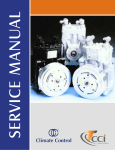
Service Manual
SECTION 2
• Service
- Clutch Servicing (Removal & Installation)
- Shaft Seal Servicing (Removal & Installation)
- Head & Valve Plate Servicing (Removal & Installation)
- Baseplate Servicing (Removal & Installation)
- Gasket Treatment
- Noise Complaints
- Seal Tool Kit Components
LAST REVISION 08/98
SUPERSEDES FORMS: 180.72-NM • 180.72-NM2 • 180.72-RP • YA77-401
®
Climate Control Inc.
A DEMIRCO COMPANY
Service
The majority of compressor parts are
made up of aluminum alloys and care
must be taken in handling not to mar,
nick or scratch. All machined surfaces
must be free of nicks and burrs to
insure proper fit and gasket seating.
When replacing parts and securing
with bolts or cap screws, the specified
torque requirements on page 15
should never be exceeded. Bolts
should all be run in until the bolt
heads make contact, then tightened
with a torque wrench in a sequence
resulting in tightening of diagonally
opposite bolts until all are drawn up to
specified torques. (Refer to torque
sequence page 15.)
An important factor in compressor
servicing is cleanliness and care
should be exercised to prevent dirt or
foreign material from entering the
compressor when it is opened. All old
gaskets should be removed and
replaced. All gasket surfaces should
be clean and all parts to be reused
should be washed in a suitable
petroleum base solvent.
2. Install clutch removal bolt into the
clutch. Using the adjustable spanner
wrench to hold the clutch pulley in
place, tighten the clutch bolt until the
clutch pulley is forced free.
CLUTCH SERVICING
REMOVAL
3. Remove the clutch mounting bolts.
INSTALLATION
1. Check that a key is properly
inserted in the shaft of the compressor.
1. Remove the clutch center bolt and
washer using the adjustable spanner
wrench to hold the clutch pulley.
Climate Control Inc.
3. Place clutch pulley over shaft
making sure to align the key way over
the shaft key.
4. Install and tighten the clutch center
bolt and washer using a torque
wrench to 20-25 ft. lbs. (27.1-33.9 Nm).
5. Spin the clutch pulley to verify there
is no interference. Verify the clutch
engages when the proper voltage is
applied.
2. Mount and center the coil bracket.
Tighten the four clutch mounting bolts
using a torque wrench to 13-19 ft. lbs.
(17.6-25.8 N-m). NOTE: Only use
bolts that have a loctite patch on the
threads.
Service Manual
SHAFT SEAL SERVICING
REMOVAL
The shaft seal assembly of the CCI
compressor is of a simplified design,
yet tight sealing, long lasting and,
when necessary, easily and quickly
replaced. CCI seals are machined to
3 helium light bands of flatness. The
carbon is lapped to the seal plate and
the fit becomes even better as the
seal assembly is “run in” during
operation.
1. Remove the compressor and place
on work bench.
The tendency to condemn a seal
assembly because of very slight
leakage is an error that is often
committed. Few if any mechanical
seal assemblies are 100% tight. The
rubbing surfaces of the seal are
separated by a very fine film of oil.
Oil carries refrigerant and minute
quantities which seep to the outside
may be detected with ultra sensitive
leak detectors which are capable of
sensing leakage totalling one ounce
of refrigerant over a twenty year
period. Such sensitivity serves a
useful purpose in critical applications
but for leak testing compressor joints
or seal, a leak detector will pick up
any leak of sufficient magnitude to
require correction. Refer to comments
on leak detector equipment, page 8.
5. Caution! Prior to removing the seal
plate screws, be certain that any
compressor internal pressure has
been relieved!
2. Brush off debris and dirt.
3. Use a clean lint free shop cloth to
wipe clean the exposed end of the
crankshaft.
Do not be too prone to condemn and
replace a seal assembly until the seal
has been given an opportunity to “run
in” and until there is definite proof that
replacement is really necessary.
If a refrigerant leak from the area
behind the compressor clutch is
verified with a refrigerant leak detector, replacement of the compressor
shaft seal is recommended. Note: Up
to a few drops of compressor oil may
normally be found in the area under
the front seal. Do not replace a seal
based on the presence of small
amounts of oil. Verify a leak with a
refrigerant leak detector before
replacement, then proceed as follows:
Climate Control Inc.
Remove the screws that hold the seal
plate in place and lift plate from the
compressor.
6. Using a flat blade screw driver, or
similar tool, pry up and remove the
seal retainer assembly. Use care not
to scratch or mar the crankshaft or
the machined face of the compressor.
4. Use Climate Control Seal Kit
488-25274
7. In nearly every case the friction ring
(boot) will not come off with the seal
retainer assembly.
Service Manual
2. Apply clean refrigerant oil to the
seal plate “O” ring and place the ring
into the seal plate “O” ring groove.
Invert the plate and observe that the
“O” ring remains in place.
8. With the tool used to remove the
seal retainer assembly, carefully pry
up and remove the friction ring (boot).
Again, use care not to scratch or mar
the crankshaft or machined face of
the compressor.
INSTALLATION
1. Use a clean, lint free shop cloth to
wipe the crankshaft clean. Note: At
this time the front main bearing is
exposed, therefore care must be
taken to prevent dirt or any type of
contamination from falling into it.
Climate Control Inc.
5. Prior to installation, check the seal
assembly to make sure that the
carbon seal ring is right side up
(narrow polished band up), and
confirm that the carbon rings notches
are aligned with the drive tabs in the
metal seal retainer. Lightly place the
seal assembly (carbon ring side up)
onto the oiled crankshaft.
3. Place a few drops of clean refrigerant oil on the face of the seal plate
between the "O" ring and the inside
diameter and with a clean finger
spread the oil into a thin film. It is
important that the surface not be over
oiled and that there is no oil between
the "O" ring groove and the outside
diameter of the seal plate.
4. Apply clean refrigerant oil around
the entire exposed end of the crankshaft. With a clean finger, uniformly
spread the oil completely over the
surface. Again, take care that no dirt
or contamination falls onto he main
bearing.
6. Insert the alignment tool into the seal
plate and lightly place the plate’s
polished face into contact with the seal
assembly. With a uniform downward
motion, use the alignment tool to push
the seal plate into contact with
Service Manual
REMOVAL
the crankcase face. Continue to hold
pressure between the seal plate and
the crankcase face while aligning and
installing the six (6) hold down
screws. Use a nut driver or similar
tool for initial tightening. Failure to
hold the seal plate against the
crankcase face until all screws are
firm against the seal plate may
result in a chipped or broken
carbon ring. Remove the centering
tool and use a star pattern sequence
to tighten the six (6) screws to a finish
torque of 5-8 ft. lb.
(7-11 N-m).
7. Install the metal dust cover, tapping
it firmly into place.
8. Install felt ring dust shield, placing it
around the seal plate and tight against
the compressor housing.
9. Reinstall the clutch, using the four
new screws supplied with the seal kit
to attach the field coil assembly,
tighten these screws to 13-19 ft.lb.
(18-26 N-m). Install the clutch armature/pulley assembly and tighten the
center bolt to 20-25 ft.lb. (27-34 N-m)
Insure that the pulley spins freely.
Remove the caps from the suction
and discharge ports, and using the
tool that tightened the center bolt,
rotate the compressor six (6) to ten
(10) revolutions to seat the carbon
ring uniformly against the seal plate.
Replace the suction and discharge
port caps.
HEAD AND VALVE PLATE
SERVICING
Prior to servicing the head and valve
plate, both service valves should be
opened to free any gas pressure
which may be in the compressor. The
cylinder head is made of aluminum
and care should be taken when
removing it not to damage the sealing
surfaces.
Climate Control Inc.
1. Remove the screws from flanged
type service valves. Note that these
four screws are longer than the
remaining head screws. If the valves
are of the Rotalock type or Tube 'O'
type, remove by loosening the hex
nuts which are a part of the valve
assembly.
2. Remove the remaining screws in
the head and remove the valve plate
and head from the cylinder by prying
or tapping under the ears which
extend from the valve plate. If the
head and valve plate adhere, hold the
head and tap the valve plate ears
away from the head with a soft
hammer. Do not hit or tap the head to
separate the head and valve plate
because damage to the head may
result.
Service Manual
BASEPLATE SERVICING
3. All gasket material adhering to the
head, valve plate, or crankcase;
should be carefully removed in such a
manner that the machined sealing
surfaces are not scratched or nicked.
REMOVAL
INSTALLATION
Valves and valve plates are furnished
only as a complete assembly.
1. Apply a thin film of clean refrigeration oil on the area of the crankcase
to be covered by the crankcase
gasket. Place the cylinder gasket in
position on the cylinder so the dowel
pins in the crankcase go through the
dowel pin holes in the cylinder gasket.
2. Apply a thin film of clean refrigeration
oil to the top and bottom valve plate
areas to be covered by gaskets. Place
the valve plate in position on the
cylinder gasket so the discharge valve
assemblies (i.e. the smaller diameter
assemblies with the restrainer over the
valve reed) are facing up and the
locating dowel pins go through the
dowel pin holes in the valve plate.
5. For a flange head, apply a thin film
of clean refrigeration oil to the service
valve flanges. Place an oiled service
valve O-ring or gasket in position on
the cylinder head service valve
flanges. Place the service valves in
position on the proper service valve
ports (suction or discharge) and insert
the four longer screws through the
service valve mounting pads, the
head, the valve plate, and into the
crankcase. For a Tube 'O' or Rotalock
head, insert the longer torx screws on
the inside of the service valve ports
and the shorter torx screws on the
outside. Insert the remaining head
screws and run in all the screws until
the heads make contact. Tighten the
head and service valve screws (using
a torque wrench) to 17-25 ft. lbs.
(23.0-33.9 N-m) in sequence as
shown on torque sequence chart,
page 15.
1. Remove the baseplate bolts.
2. Remove baseplate and gasket. If
the baseplate is stuck, lightly tap the
edges of the baseplate with a soft
hammer.
3. Remove any gasket material
adhering to the baseplate or crankcase. This should be done in a
manner such that the sealing surfaces are not scratched or nicked.
INSTALLATION
1. Apply a thin film of refrigeration oil
to a new gasket and the sealing
surface of the crankcase and baseplate.
3. Place the head gasket, with the bead
facing up, in position on the valve plate
so the dowel pins go through the dowel
pin holes in the gasket.
4. Apply a light film of clean refrigeration oil on the machined surface of the
cylinder head which matches the head
gasket. Place the head on the cylinder
head gasket so the dowel pins go into
the dowel pin holes in the head.
Climate Control Inc.
2. Properly align the gasket on the
crankcase.
Service Manual
NOTES ON NOISE COMPLAINTS
Many of the noise complaints can be traced to mount and drive and other related
component problems. Normally if the unit is noisy at one speed and this noise
clears up at another, it is not usually due to the compressor. Each vehicle has its
critical frequencies where all vibrations get into the correct harmony to generate
sound or noise. The speed at which these critical points are found will vary with
each vehicle and each mount and drive arrangement. By changing the mount
and drive components the noise level may be reduced.
Many times the noise generated can be eliminated or greatly reduced by changing the belt adjustment to a different tension. A tension of 100 -120 lbs. (45-54
kg) is considered normal.
3. Install the baseplate and bolts.
Tighten baseplate bolts to 10-16 ft.
lbs. (13.6-21.7 N-m) in sequence
given on page 15 using a torque
wrench.
GASKET TREATMENT
Before assembly to the compressor,
all gaskets should be dipped in clean
refrigeration oil of the type used in the
crankcase.
Noises emanating from the clutch are difficult to recognize because of the close
connecting feature with the compressor. A loose bolt holding the clutch to the
shaft will result in extremely noisy operation. Extreme care must be exercised
to prevent the removal of the wrong component.
Since a compressor has many moving parts, it is normal for it to generate some
noise just as a motor generates some noise as it is operated. The refrigerant
gases, as they are moved by the compressor pistons, also produce noises and
vibrations as a normal situation.
Gaskets are made of a neoprene
composition fiber and wicking action
will result as oil follows the fiber. Do
not mistake this wicking action for
leaking. Wicking is a normal condition
and is to be expected.
CLASSIC # 22-1272
CCI (YORK) ESSENTIAL SEAL TOOL KIT
1
2
3
4
5
6
99-431 99-474 99-499 99-440 -
CCI and Tecumseh Oil Level Checker
Seal Installer and Plate Alignment Tool
Universal Clutch Holder Wrench
Clutch Remover 5/8 x 11 Thread
(CCI and Tecumseh)
99-441 - Clutch Remover 5/8 x 18 Thread
(CCI and Tecumseh)
99-473 - Universal Seal Remover
BASIC COMPRESSOR TOOLS AVAILABLE THROUGH:
CLASSIC TOOL DESIGN, INC. 31 WALNUT STREET • NEW WINDSOR, NY 12553
PH. 914-562-8700 • FAX 914-562-8596
Climate Control Inc.
Service Manual
®
Climate Control Inc.
A DEMIRCOTM Company
2120 N. 22nd Street
Decatur, Illinois 62526
Telephone: 217-422-0055
FAX: 217-422-4323
www.ccicompressor.com
Information contained in this publication was in effect at the time the publication was approved for printing and is subject to change
without notice or liability. Climate Control Inc. reserves the right to revise the information presented at any time.
© Copyright 1999 Climate Control Inc. All rights reserved


