1
ADJUSTMENTS (Continued)
INDEX FINGER PROXIMITY SETTING
Set all motor switches to the off position.
Put the grind selector switch in the jog cycle.
Press the machine system start switch, so the grinder is
operational.
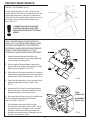
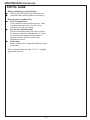
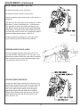
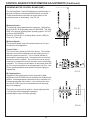
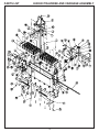
Push down on the index finger until the stop pin is within
.06 inches (1.5 mm) of bottoming out. (You can use a
1/16" gage pin or rod stock between the stop pin and
index finger). Set the proximity switch to activate the light
at this setting. This assures the index finger to be close
to its final stop position so the reel is completely indexed
before the carriage starts to traverse. See FIG. 19.
FIG. 19
The spring load force pushing up on the index finger
brings it away from the proximity when released.
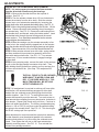
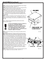
STEPPPER INFEED TRAVEL LIMITS
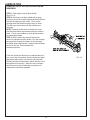
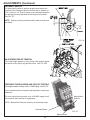
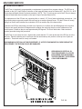
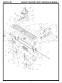
The infeed stepper maximum extension is 6.0" (152
mm) abd minimum compression is 3.5" (89 mm). If you
experience a situation where the grind does not properly
finish, checkthat you have not exceeded stepper travel
by checking the values per FIG. 20.
FIG. 20
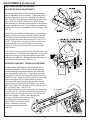
LOCKING INDEX FINGER PIN
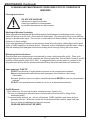
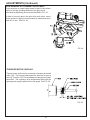
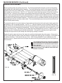
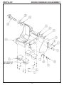
To align the Index Finger Locking Pin to the hole in the
Index Finger Assembly loosen the two socket head cap
screws so the index sensor block is movable. Push
down on the index finger assembly until the spring
loaded index finger locks into hole with no binding.
Tighten the two socket head cap screws so the index
sensor block is secured, and the locking pin moves
freely. See FIG. 21.
FIG. 21
19