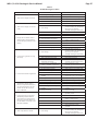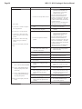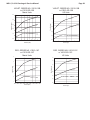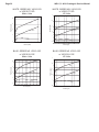
1
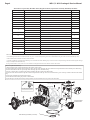
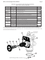
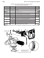
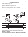
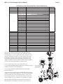
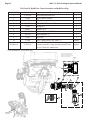
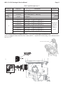
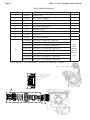
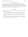
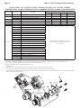
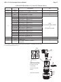
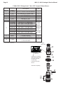
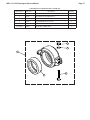
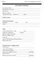
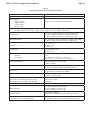
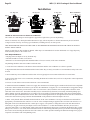
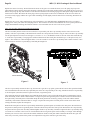
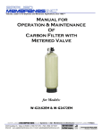
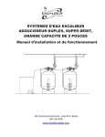
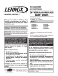
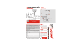
Water Specialist 1.5", 2" and 2L
Control Valve Drawings & Service Manual
Table of Contents
WS1.5 Drive Cap Asy, Downflow Piston, Regenerant Piston, Spacer Stack Asy, Main Body and Meter ....................4
WS2L Drive Cap Asy, Downflow Piston, Regenerant Piston, Spacer Stack Asy and Main Body ................................5
WS2 Drive Cap Asy, Downflow Piston, Regenerant Piston, Spacer Stack Asy and Main Body ..................................6
Meter Assembly for WS2 and WS2L Valves .................................................................................................................7
WS1.5 and 2L Injector Cap, Injector Screen, Injector, Plug, Bolts and O-Ring ...........................................................8
WS2 Injector Valve Body, Refill Flow Control and Injector .........................................................................................9
WS1.5 and 2L Refill Flow Control Assembly and Refill Port Plug .............................................................................10
WS1.5 and 2L Drain Line ¾” ...................................................................................................................................... 11
WS1.5 and 2L Drain Line 1” .......................................................................................................................................12
WS1.5 and 2L Drain Line Option ................................................................................................................................13
WS2 Drain Line ...........................................................................................................................................................13
V3053 WS2 2-1/2 Groovelock Clamp Assembly ........................................................................................................17
Installation Summary ...................................................................................................................................................18
General Specifications and Pre Installation Check List ...............................................................................................19
Installation....................................................................................................................................................................20
Service Instructions......................................................................................................................................................23
Troubleshooting Procedures ........................................................................................................................................27
Injector Graphs for WS1.5 & WS2L............................................................................................................................29
Injector Graphs for WS2 ..............................................................................................................................................33
Page 4
WS1.5, 2 & 2L Drawings & Service Manual
WS1.5 Drive Cap Assembly, Downflow Piston, Regenerant Piston, Spacer Stack Assembly, Main Body and Meter
Drawing No.
Order No.
1
V3004
WS1 Drive Cap Asy
2
V3135
O-ring 228
1
3
V3407
WS1.5 Piston Downflow Asy
1
4
V3174*
WS1 Regenerant Piston
1
5
V3423
WS1.5 Backplate Dowel
1
6
V3430
WS1.5 Spacer Stack Asy
1
7
Back Plate
Refer to Programming and Cover Drawing Manual
1
8
V3419
O-ring 347
1
V3418
O-ring 328 for valve bodies with NPT threads
V3441
O-ring 226 for valve bodies with BSPT threads
V3437
WS1.5 Flow Straightener (located inside meter housing)
9
Not Shown
Description
V3401-01
10
V3632***
12
V3003-02**
13
V3118-03
14
15
1
1
WS1.5/2/3 Meter Retaining Clip
1
WS1.5/2L/2H Meter Commercial Asy
1
WS1.5/2L Turbine Asy
1
V3105
O-ring 215
1
V3501
WS1.5/2 TURBINE CLIP
1
WS1.5 Valve Body Downflow
V3400BSPT-01
Not Shown
1
WS1.5 Meter Housing BSPT
V3400-01
16
1
WS1.5 Meter Housing
V3401BSPT-01
11
Quantity
1
WS1.5 Valve Body Downflow BSPT
D1300
TOP BAFFLE DFSR CLACK 1.5/50MM
1
BSPT threads on inlet and outlet ports on the V3400BSPT-01 and V3401BSPT-01. NPT threads on drain and injector ports on V3400BSPT-01.
*V3174 WS1 Regenerant Piston not used for backwash only valves. V3010-15Z Injector Plug and V3195-01 WS1 Refill Port Plug ASY must be used for backwash only valves.
**Order number V3003-02 includes V3118-03, V3501 and V3105.
***In 2008, a modification was made to Meter Housing to use V3632 WS1.5/2/3 Meter Retaining Clip. Do not use V3632 on old style housings which have holes through the casting to
accept the U-shaped V3223 WS2 Meter Clip.
If using a meter on WS1.5” valves, select 1.5 if valve software records in gallons and 38 if valve software records in cubic meters.
Service or replace the turbine by:
1. Turn the bypass for the system off and relieve the pressure on the system.
2. Press downward on the remote meter assembly to relieve tension on the retaining clip V3632. Remove the clip and take the meter assembly out of the housing.
3. Remove the bend from the two exposed tips of the retaining clip V3501 and remove clip.
4. Service or replace the V3118-03 WS15/2 Turbine Assembly and place it back in the turbine shaft.
5. Insert the V3501 WS15/2 Turbine Clip and re-bend the exposed ends of the clip. The V3118-03 turbine has a groove to line up with the V3501 WS15/2 Turbine
Clip.
6. Insert meter assembly back into the meter housing.
7. Re-install the meter retaining clip V3632 as shown below.
8. Open the bypass for the system slowly to bring back into service and check to be sure you have no water leaks.
11
B or indent indicates BSPT
N or no mark indicates NPT
Typical meter retaining clip installation.
Ensure clip is fully engaged in groove
and tabs positioned in slot as shown.
7
12
16
13
1
6
2
15
14
3
4
B indicates BSPT
N indicates NPT
5
10
8
Install D1300 upper diffuser (not shown)
9
WS1.5, 2 & 2L Drawings & Service Manual
Page 5
WS2L Drive Cap Assembly, Downflow Piston, Regenerant Piston,
Spacer Stack Assembly and Main Body
Drawing No.
1
2
3
4
5
6
7
8
Order No.
V3004
V3135
V3407
V3174*
V3423
V3430
Back Plate
V3419
V3418
V3441
H1023-03
JG-PP481222W
V3453-03
V3453BSPT-03
V3468
V3465
9
Not Shown
Not Shown
10
Not Shown
Not Shown
D1300
Description
Quantity
1
1
1
1
1
1
1
1
WS1 Drive Cap Asy
O-ring 228
WS1.5 Piston Downflow Asy
WS1 Regenerant Piston
WS1.5 Backplate Dowel
WS1.5 Spacer Stack Asy
Refer to Programming and Cover Drawing Manual
O-ring 347
O-ring 328 for valve bodies with NPT threads
O-ring 226 for valve bodies with BSPT threads
TubePoly 3/8 x 1/4 Blk 500 Ft. Roll
Elbow Fix 3/8 x 1/4 NPTF Polypro
WS2L Body 4-8 NPT w/V3468 Plug
WS2L Body 4-8 BSPT w/V3465 Plug
WS2 Plug 1/4 Hex NPT (included when ordering V3453-03)
WS2 Plug 1/4 Hex BSPT (included when ordering V3453 BSPT-03)
1
.0006
2
1
2
TOP BAFFLE DFSR CLACK 1.5/50MM
1
BSPT threads on inlet and outlet ports on the V3453BSPT-03. NPT threads on drain and injector ports on V3435BSPT-03.
*V3174 WS1 Regenerant Piston not used for backwash only valves. V3010-15Z Injector Plug and V3195-01 WS1 Refill Port Plug
ASY must be used for backwash only valves.
7
B indicates BSPT
N indicates NPT
10
6
2
3
4
1
5
8
9
Install D1300 upper diffuser (not shown)
Page 6
WS1.5, 2 & 2L Drawings & Service Manual
WS2 Drive Cap Assembly, Downflow Piston, Regenerant Piston,
Spacer Stack Assembly and Main Body
Drawing No.
1
2
3
4
5
6
7
8
9
10
11
Not Shown
Order No.
V3726
V3725
V3452
V3728
V3724
V3642
Back Plate
V3729
V3419
V3641
V3441
V3700-01
V3700BSPT-01
V3468
V3465
Not Shown
D1300
Description
Quantity
1
1
1
1
4
4
1
1
WS2 BRINE PISTON ASY
WS2 PISTON DOWNFLOW ASY
O-RING 230
WS2 DRIVE CAP ASY
WASHER FLAT SS 1/4
BOLT BHCS S/S 1/4-20X1.25
Refer to Programming and Cover Drawing Manual
WS2 STACK ASY
O-RING 347 FOR WS15
O-RING 225 for valve bodies with NPT threads
O-RING 226 for valve bodies with BSPT threads
WS2 BODY NPT
WS2 BODY BSPT
WS2H PLUG 1/4 HEX NPT
WS2H PLUG 1/4 HEX BSPT
1
1
1
TOP BAFFLE DFSR CLACK 1.5/50MM
1
BSPT threads on inlet and outlet ports on the V3700BSPT-01. NPT threads on the drain port on V3700BSPT-01.
7
1
2
4
3
B indicates BSPT
N indicates NPT
5
6
8
11
10
9
Drive bracket can be removed
by sqeezing (2) lock tabs
& rotating counter clockwise.
Install D1300 upper diffuser (not shown).
WS1.5, 2 & 2L Drawings & Service Manual
Page 7
Meter Assembly for WS2 and WS2L Valves
Note: Only 2" meters should be used on WS2 valves.
Standard meter cable used for spacing up to 3" between valve body and meter body, longer distance requires longer cable #V3221.
Service or replace the turbine by:
1. Turn the bypass for the system off and relieve the pressure on the system.
2. Press downward on the remote meter assembly to relieve tension on the retaining clip V3632 (or the U-shaped V3223 WS2 Meter
Clip). Remove the clip and take the meter assembly out of the housing.
3. Remove the bend from the two exposed tips of the retaining clip V3501 and remove clip.
4. Service or replace the V3118-03 WS15/2 Turbine Assembly and place it back in the turbine shaft.
5. Insert the V3501 WS15/2 Turbine Clip and re-bend the exposed ends of the clip. The V3118-03 turbine has a groove to line up
with the V3501 WS15/2 Turbine Clip.
6. Insert meter assembly back into the meter housing.
7. Re-install the meter retaining clip V3632 as shown below (or the U-shaped V3223 WS2 Meter Clip).
8. Open the bypass for the system slowly to bring back into service and check to be sure you have no water leaks.
The V3118-03 has a groove to line up with the V3501 WS1.5/2 Turbine Clip.
6b
1
B indicates BSPT
N indicates NPT
B indicates BSPT
N indicates NPT
Typical meter retaining clip installation.
Ensure clip is fully engaged in groove
and tabs positioned in slot as shown.
Bend clip
after install
2
4
Area of
detail
3
6a
5
Drawing No.
Order No.
1
2
3
4
V3003-02*
V3118-03
V3105
V3501
V3222-01
V3222BSPT-01
V3223
V3632**
V3488
5
6a
6b
Not Shown
Description
WS1.5/2L/2H Meter Commercial Asy
WS1.5/2 Turbine Asy
O-Ring 215
WS1.5/2 Turbine Clip
WS2 Meter NPT Housing
WS2 Meter BSPT Housing
WS2 Meter Clip
WS1.5/2/3 Meter Retaining Clip
WS2 Flow Straightener (located inside meter housing)
Quantity
1
1
1
1
1
1
1
1
Installation of the WS2 Meter NPT Assembly can be accomplished with 2” NPT pipe or by using a 2½” groove lock coupling. For
WS2 Meter BSPT Assembly use 63mm pipe. When installing the WS2 Meter Assembly it is necessary that the meter be installed in
a horizontal position. After installing the meter, break out the tab in the back plate and thread the meter cord through.
WHEN INSTALLING THE METER, MAKE SURE THE ARROW ON THE METER BODY IS GOING THE SAME
DIRECTION AS THE WATER FLOW.
OPERATING PRESSURES: 20 PSI MINIMUM / 125 PSI MAXIMUM • OPERATING TEMPERATURES: 40°F MINIMUM /
110°F MAXIMUM
*Order number V3003-02 includes V3118-03, V3501 and V3105.
** In 2008 a modification was made to Meter Housings to use V3632 WS1.5/2/3 Meter Retaining Clip. Do not use V3632 on old
style housings which have holes through the castings to accept the U-shaped V3223 WS2 Meter Clip.
Page 8
WS1.5, 2 & 2L Drawings & Service Manual
WS1.5 and 2L Injector Cap, Injector Screen, Injector, Plug, Bolts and O-Ring(s)
Drawing No.
1
2
3
4
5
Not Shown
Not Shown
Order No.
V3422
V3403
V3417
V3010-15B
V3010-15C
V3010-15D
V3010-15E
V3010-15F
V3010-15G
V3010-15H
V3010-15Z
V3404
V3171
V3416
Description
Bolt
WS1.5 Injector Cap
O-ring 220
WS1.5 Injector Asy B Violet
WS1.5 Injector Asy C Red
WS1.5 Injector Asy D White
WS1.5 Injector Asy E Blue
WS1.5 Injector Asy F Yellow
WS1.5 Injector Asy G Green
WS1.5 Injector Asy H Orange
WS1.5 Injector Plug
WS1.5 Injector Screen
O-ring 013
O-ring 012
Quantity
3
1
1
1
1
*
*
*The injector or the injector plug each contain one V3416 o-ring 012 (lower) and one
V3171 o-ring 013 (upper).
WS1 & 1.25
INJECTOR PLUG
WS1.5
INJECTOR PLUG
Injector Location on WS2L
BLACK
DO NOT USE ON
WS1.5” VALVES
1
2
WS1 & 1.25
INJECTOR
WS1.5
INJECTOR
ALL THROATS ARE
COLORED
AND ALL NOZZLES
ARE WHITE
ALL THROATS ARE
BLACK
AND ALL NOZZLES
ARE COLORED
3
Injector Nozzle Color
Injector Throat Black
4
5
1.730"
1¾”
DO NOT USE ON
WS1.5” VALVES
2.075"
WS1.5, 2 & 2L Drawings & Service Manual
Page 9
WS2 Injector Valve Body, Refill Flow Control and Injector
Drawing No.
1
2
3
4
5
6
7
8
9
10
11
12
13
14
15
16
Not Shown
Not Shown
Not Shown
Order No.
V3477
V3152
V3727
V3010-2R-15B
V3010-2S-15C
V3010-2T-15D
V3010-2U-15E
V3010-2V-15F
V3010-2W-15G
V3010-2X-15H
V3010-2A
V3010-2B
V3010-2C
V3010-2D
V3010-2E
V3010-2F
V3010-2G
V3731
V3730
V3315
V3724
V3643
V3162-022*
V3231
V3277
V3105
V3150
V3151
V3149
V3189
H4915**
V3499
Description
WS2H INJECTOR CAP
O-RING 135
WS2 INJECTOR BODY ASY
WS2/2H INJECTOR R ASY W/V3010-15B
WS2/2H INJECTOR S ASY W/V3010-15C
WS2/2H INJECTOR T ASY W/V3010-15D
WS2/2H INJECTOR U ASY W/V3010-15E
WS2/2H INJECTOR V ASY W/V3010-15F
WS2/2H INJECTOR W ASY W/V3010-15G
WS2/2H INJECTOR X ASY W/V3010-15H
WS2/2H INJECTOR ASY A
WS2/2H INJECTOR ASY B
WS2/2H INJECTOR ASY C
WS2/2H INJECTOR ASY D
WS2/2H INJECTOR ASY E
WS2/2H INJECTOR ASY F
WS2/2H INJECTOR ASY G
WS2 INJ DRAW TUBE DOWN ASY
WS2 INJ FEED TUBE DOWN ASY
O-RING 231
WASHER FLAT SS 1/4
BOLT BHCS S/S 1/4-20x2.25
WS1 DLFC 022 FOR 3/4
WS2H REFILL FLOWCNTRL RETAINER
O-RING 211
O-RING 215
WSI SPLIT RING
WS1 NUT 1 QC
WS1 FTG 1 PVC MALE NPT ELBOW
WS1 FTG 3/4&1 PVC SLVNT 90
FTG KIT 494 BV 1/2 POLYTUBE
WS2H FITTING CAP 1 IN THREADED
Quantity
1
1
1
1
1
1
1
4
4
1
1
1
1
1
1
1
Optional
Optional
Optional
*Any V3162-XXX flow control may be used. WS2 valves are
shipped with a V3162-022 (2.2 gpm) flow control. Flow control
sizes range from 0.7 up to 10 gpm. WS2 valves can only be set for
minutes of fill because various sizes of flow controls can be used.
To calculate for pounds or kilograms of salt, take minutes of fill
times the flow rate of the flow control being used to arrive at the
number of gallons of water be added to the brine tank. Each gallon
of water will dissolve approximately 3 pounds of salt.
16
15
14
13
12
**Use of H4915 may severely reduce brine draw rates.
A V3731 WS2 INJ DRAW TUBE DOWN ASY contains one D1262
O-RING 118 and two V3639 O-RING 119.
11
Proper RFC orientation
directs refill water flow
toward the washer face
with radius and text. Water Flow
A V3730 WS2 INJ FEED TUBE DOWN ASY contains three
V3638 O-RING 113.
10
7
9
6
V3010-2X injectors and the V3010-15ADAPTER contain a V3283
O-RING 117 and a V3284 O-RING 114. The V3010-15ADAPTER
can be used with any V3010-15X injector so the 2” valve can be
used on smaller tank sizes. The V3010-15X injector contains one
V3416 O-RING 012 (lower) and one V3171 O-RING 013 (upper).
Backwash Only Valves include a V3499 but do not include the
following parts: V3189, H4915, V3162-022, V3231 and V3277.
8
1
2
5
4
3
Page 10
WS1.5, 2 & 2L Drawings & Service Manual
WS1.5 and 2L Refill Flow Control Assembly and Refill Port Plug
Drawing No.
1
2
3
4
5
6
7
8
9
10
Order No.
V3195-01
V3415
H4615
V3428*
V3163
H4612
JCPG-8PBLK
JCP-P-8
V3182
V3498
Not Shown
V3434-01
Description
WS1 Refill Port Plug Asy
WS1.5 BLFC Adapter
Clip Retaining
WS1.5 Refill Retainer ASY
O-ring 019
Elbow Cap ½”
Nut Compression ½” Black
Insert Polytube ½”
WS1 RFC
WS1.5 Brine Elbow Asy w/RFC ½”
WS1.5 Refill Asy 5/8 x 3/4 (includes fitting, refill
retainer assembly, o-ring, nut and polytube insert
for 5/8” brine line connection)
Quantity
1
1
1
1
1
1
1
1
1
Option
Option
*V3428 contains a V3182 WS1 RFC
Proper RFC orientation
directs refill water flow
towards the washer face
with rounded edges
Water Flow
12
9
2
10
3
5
6
4
7
10
1
4
5
5
11
9
10
1
5
Refill location
on WS2L
8
WS1.5, 2 & 2L Drawings & Service Manual
Page 11
WS1.5 and 2L Drain Line ¾”
Drawing No.
1
2
3*
4
5*
Order No.
H4615
V3414
V3158-01
V3163
V3159-01
Description
Locking Clip
WS1.5 DLFC Adapter
WS1 Drain Elbow ¾” Male Asy
O-ring 019
WS1 DLFC Retainer Asy
6
V3162-032
V3162-042
V3162-053
V3162-065
V3162-075
V3162-090
V3162-100
WS1 DLFC 3.2 gpm (12.1 lpm) for ¾”
WS1 DLFC 4.2 gpm (15.9 lpm) for ¾”
WS1 DLFC 5.3 gpm (20.1 lpm) for ¾”
WS1 DLFC 6.5 gpm (24.6 lpm) for ¾”
WS1 DLFC 7.5 gpm (28.4 lpm) for ¾”
WS1 DLFC 9.0 gpm (34.1 lpm) for ¾”
WS1 DLFC 10.0 gpm (37.9 lpm) for ¾”
Quantity
1
1
1
1
1
One DLFC
must be
used if ¾”
fitting is
used
* 3 & 5 can be ordered as a complete assembly - V3331 WS1 Drain Elbow and Retainer Asy
Valves are shipped without drain line flow control (DLFC) – install DLFC before using. Use a minimum drain
line size of ¾”.
Drain Line location on WS2L
4
3
5
6
1
2
Page 12
WS1.5, 2 & 2L Drawings & Service Manual
WS1.5 and 2L Drain Line 1”
Drawing No.
1
2
3
4*
5*
6*
7*
8*
9*
Order No.
H4615
V3414
V3008-02
V3163
V3167
V3151
V3150
V3105
V3166
V3190-090
V3190-100
V3190-110
V3190-130
V3190-150
V3190-170
V3190-200
V3190-250
10
Description
Locking Clip
WS1.5 DLFC Adapter
WS1 Drain Ftg 1” Straight
O-ring 019
WS1 Drain Ftg Adapter 1”
WS1 Nut 1” QC
WS1 Split Ring
O-ring 215
WS1 Drain Ftg Body 1”
WS1 DLFC 9.0 gpm (34.1 lpm) for 1”
WS1 DLFC 10.0 gpm (37.9 lpm) for 1”
WS1 DLFC 11.0 gpm (41.6 lpm) for 1”
WS1 DLFC 13.0 gpm (49.2 lpm) for 1”
WS1 DLFC 15.0 gpm (56.8 lpm) for 1”
WS1 DLFC 17.0 gpm (64.4 lpm) for 1”
WS1 DLFC 20.0 gpm (75.7 lpm) for 1”
WS1 DLFC 25.0 gpm (94.6 lpm) for 1”
* Can be ordered as a set, order number V3008-02 WS1 Drain Ftg 1” Straight
Drain Line location on WS2L
Proper DLFC orientation
directs water flow towards
the washer face with
rounded edge
Water Flow
3
9
10
8
7
6
5
4
1
2
Quantity
1
1
1
1
1
1
1
1
1
One
DLFC
must be
used if 1”
fitting is
used
WS1.5, 2 & 2L Drawings & Service Manual
Page 13
WS1.5 and 2L Drain Line Option
The drain port on the WS1.5 & 2L is 1.25” Female NPT threads. V3079 WS DLFC ASY 125 FNPT/15
FNPT and V3079BSPT WS DLFC ASY 125 FNPT/15 FBSPT are options are available for purchase to
control the rate of flow to drain. Requires one V3190-XXX drain line flow control washer and up to six of the
V3162-XXX drain line flow control washers. Flow rate ranges from 9 gpm up to 85 gpm. Requires separate
purchase of a length (dependant on back plate dimensions) of male NPT to male NPT threaded pipe or fitting
and put Teflon tape on both ends. Remove the existing fitting from the valve body.
WS2 Drain Line
The drain port on the WS2 is 1.5” Female NPT threads. The following options are available for purchase
to control the rate of flow to drain:
• V3158-04 WS2 DRN ELBOW 3/4 90 W/O SIL. Accepts one V3162-XXX drain line flow control
washer with flow rate range up to 10 gpm. Adapter and reducing bushing included in assembly.
• V3008-05 WS2 FTG DRAIN 1 STRT W/O SIL. Accepts one V3190-XXX drain line flow control
washer with flow rate range from 9 gpm up to 25 gpm. Adapter and reducing bushing included in
assembly.
• V3080 WS DLFC ASY 15 MNPT/15 FNPT or V3080BSPT WS DLFC ASY 15 MNPT/15 FBSPT.
Requires one V3190-XXX drain line flow control washer and up to six of the V3162-XXX drain line
flow control washers. Flow rate ranges from 9 gpm up to 85 gpm.
Page 14
WS1.5, 2 & 2L Drawings & Service Manual
V3079 WS DLFC ASY 125 FNPT/15 FNPT, V3079BSPT WS DLFC ASY 125 FNPT/15 FBSPT,
V3080 WS2 DLFC Assembly 15 MNPT/15 FNPT or V3080BSPT WS DLFC Assembly 15 MNPT/15 FBSPT
Drawing No.
Order No.
1
V3081
V3645
V3645BSPT
V3646
V3647
V3652
V3441
V3162-007
V3162-010
V3162-013
V3162-017
V3162-022
V3162-027
V3162-032
V3162-042
V3162-053
V3162-065
V3162-075
V3162-090
V3162-100
V3190-090
V3190-100
V3190-110
V3190-130
V3190-150
V3190-170
V3190-200
V3190-250
2
3
4
5
6
Not Shown
Description
Quantity
V3079BSPT
V3080
1
1
1
1
1
1
4
4
1
1
V3079
1
1
WS15 RETAINER DLFC ASY
WS15 DLFC FLANGE OUTLET FNPT
WS15 DLFC FLANGE OUTLET FBSPT
WS15 DLFC FLANGE INLET MNPT
WS125 DLFC FLANGE INLET FNPT
BOLT HEXHD S/S HCS 5/16-18x3/4
O-RING 226
WS1 DLFC 0.7 gpm for 3/4
WS1 DLFC 1.0 gpm for 3/4
WS1 DLFC 1.3 gpm for 3/4
WS1 DLFC 1.7 gpm for 3/4
WS1 DLFC 2.2 gpm for 3/4
WS1 DLFC 2.7 gpm for 3/4
WS1 DLFC 3.2 gpm for 3/4
WS1 DLFC 4.2 gpm for 3/4
WS1 DLFC 5.3 gpm for 3/4
WS1 DLFC 6.5 gpm for 3/4
WS1 DLFC 7.5 gpm for 3/4
WS1 DLFC 9.0 gpm for 3/4
WS1 DLFC 10.0 gpm for 3/4
WS1 DLFC 09.0 gpm for 1
WS1 DLFC 10.0 gpm for 1
WS1 DLFC 11.0 gpm for 1
WS1 DLFC 13.0 gpm for 1
WS1 DLFC 15.0 gpm for 1
WS1 DLFC 17.0 gpm for 1
WS1 DLFC 20.0 gpm for 1
WS1 DLFC 25.0 gpm for 1
1
4
1
V3080BSPT
1
1
1
4
1
Install at least one V3190-XXX in center hole.
Knock out plugs allow installation of up to 6 more
of V3162-XXX.
Assemblies are shipped without drain line flow control (DLFC). Assembly instructions:
1. Determine the desired flow rate. Select one V3190-XXX for the center hole and a combination of V3162-XXX to arrive at the desired flow rate.
At least one V3190-XXX must be used and up to six of the V3162-XXX may be used.
2. Using a drill or punch remove the desired knockout(s) in V3081.
3. Smooth holes.
4. Install appropriate size(s) of drain line flow control washers. Play close attention to proper DLFC orientation.
5. Fit V3441 o-ring onto V3081 Retainer DLFC Asy and assemble. Properly orientate the V3081 in direction of flow.
6. Inlet threads for 1.25” female are NPT. Inlet threads for 1.5” male are NPT. Outlet threads for 1.5” are either female NPT or BSPT. 1.5” female outlet is stamped
with N or B to indicate NPT or BSPT.
5
2
Washer
Radius
6
w
n
tio
of
Flo
rec
Di
1
4
3
DLFC not supplied.
At least one V3190-XXX
must be installed in
center hole.
Plugs may be knocked out
low
or drilled to use up to six
fF
V3162-XXX.
no
tio
ec
r
i
D
B indictates BSPT
N indicates NPT
WS1.5, 2 & 2L Drawings & Service Manual
Page 15
V3158-04 WS2 Drain Elbow 3/4" Male NPT Without Silencer
Drawing
Number
1
2
3
5
6
Order
Number
V3649
V3414
H4615
V3162-007
V3162-010
V3162-013
V3162-017
V3162-022
V3162-027
V3162-032
V3162-042
V3162-053
V3162-065
V3162-075
V3162-090
V3162-100
V3159-01
V3163
7
V3158-03
4
Description
Qty
BUSHING PVC SCH80 1.5/1.25 NPT
WS15 DLFC ADAPTER
CLIP RETAINING 474/WS1
WS1 DLFC 0.7 gpm for 3/4
WS1 DLFC 1.0 gpm for 3/4
WS1 DLFC 1.3 gpm for 3/4
WS1 DLFC 1.7 gpm for 3/4
WS1 DLFC 2.2 gpm for 3/4
WS1 DLFC 2.7 gpm for 3/4
WS1 DLFC 3.2 gpm for 3/4
WS1 DLFC 4.2 gpm for 3/4
WS1 DLFC 5.3 gpm for 3/4
WS1 DLFC 6.5 gpm for 3/4
WS1 DLFC 7.5 gpm for 3/4
WS1 DLFC 9.0 gpm for 3/4
WS1 DLFC 10 gpm for 3/4
WS1 DLFC RETAINER ASY
O-RING 019
WS1 DRN ELBOW 3/4 MALE
NO HOLE
1
1
1
ONE
DLFC MUST BE USED IF
¾”
FITTING IS USED.
1
1
1
This assembly is shipped without drain line flow control (DLFC) – install DLFC before using.
Use a minimum drain line size of ¾”.
Apply
Teflon Tape
7
6
5
Water flow
Proper DLFC orientation
directs water flow toward
the washer face with
rounded edge.
Lubricate o-rings with
silicone.
4
3
2
Apply
Teflon
Tape
Order DLFC separately
1
Page 16
WS1.5, 2 & 2L Drawings & Service Manual
V3008-05 WS2 Fitting Drain 1" Male NPT Straight Without Silencer
Drawing
Number
1
2
3
4
5
6
7*
8
9
10
Order
Description
Number
V3166-01 WS1 FTG FLOW CONTROL BODY
V3167
WS1 DRAIN FTG ADAPTER 1
V3163
O-RING 019
V3150
WS1 SPLIT RING
V3151
WS1 NUT 1” QC
V3105
O-RING 215
V3190-090
WS1 DLFC 9.0 GPM FOR 1
V3190-100
WS1 DLFC 10.0 GPM FOR 1
V3190-110
WS1 DLFC 11.0 GPM FOR 1
V3190-130
WS1 DLFC 13.0 GPM FOR 1
V3190-150
WS1 DLFC 15.0 GPM FOR 1
V3190-170
WS1 DLFC 17.0 GPM FOR 1
V3190-200
WS1 DLFC 20.0 GPM FOR 1
V3190-250
WS1 DLFC 25.0 GPM FOR 1
H4615
CLIP RETAINING
V3414
WS1.5 DLFC ADAPTER
BUSHING PVC SCH 80
V3649
1.5 TO 1.25 NPT
Qty
1
1
1
1
1
1
ONE
DLFC
MUST BE
USED IF
1”
FITTING
IS USED.
1
1
1
* Order DLFC separately.
Apply
Teflon Tape
1
7
Water flow
6
Proper DLFC orientation
directs water flow toward
the washer face with
rounded edge.
4
5
Lubricate o-rings with
silicone.
Order DLFC separately
2
8
3
9
Apply
Teflon
Tape
10
WS1.5, 2 & 2L Drawings & Service Manual
Page 17
V3053 WS2 2-1/2 GROOVELOCK CLAMP ASY
Drawing No.
Order No.
Description
Quantity
1
V3053
WS2 2-1/2 GROOVELOCK CLAMP ASY
1
2
V3290
WS2 GROOVE LOCK SEAL 2.5
1
3
V3269
WS2 NUT 5/16-18 SS HEX
1
4
V3293
WS2 WASHER SS 5/16 FLAT
1
5
V3276
WS2 BOLT HEX SS 5/16-18X1-3/4
1
Not Shown
S3086
SILICONE LUBRICANT
1
3
4
1
5
2
Page 18
WS1.5, 2 & 2L Drawings & Service Manual
Installation Summary
Installation Date: ___________________________________________
Installation Location: _______________________________________
Installer(s): _______________________________________________
Phone Number: ____________________________________________
Application Type: (Softener) _______ Other: ____________________
Water Source: ____________________________________________
Water Test Results:
Hardness:___________ Iron: ___________pH:___________________
Other: ___________________________________________________
_________________________________________________________
Misc:
Service Flow Rates: min. _________ max. ___________
Tank Size: Diameter _________ Height: ______________
Resin or Media Volume: ___________________________
Resin or Media Type: _____________________________
Capacity: _______________________________________
Salt or Fill Setting per Regeneration: _________________
Brine Tank Size: _________________________________
Control Valve Configuration:
Valve Type: _____________________________________
Valve Part Number: _______________________________
Valve Serial Number: _____________________________
Regenerant Refill Control: _________________ gpm/lpm
Injector Size: ____________________________________
Drain Line Flow Control: __________________ gpm/lpm
WS1.5, 2 & 2L Drawings & Service Manual
Page 19
Table 1
General Specifications and Pre-Installation Checklist
Minimum/Maximum Operating Pressures
20 psi (138 kPa) -125 psi (862 kPa)
Minimum/Maximum Operating Temperatures
40°F (4°C) - 110°F (43°C)
Power Adapter:
Supply Voltage
Supply Frequency
Output Voltage
Output Current
See Front Cover and Drive Assembly drawing
No user serviceable parts are on the PC board, the motor, or the Power adapter. The means of
disconnection from the main power supply is by unplugging the Power adapter from the wall.
Service flow rate
Backwash flow rate
CV Service
CV Backwash
1.5” Valve: 60 gpm (227 lpm) @ 15 psig (103 kPa) drop
2L Valve: 75 gpm (284 lpm) @ 15 psig (103 kPa) drop
2" Valve: 115 gpm (435 lpm) @ 15 psig (103kPa) drop
1.5" & 2L Valve: 50 gpm (189 lpm) @ 25 psig (172 kPa) drop
2" Valve: 80 gpm (303 lpm) @ 25 psig (172kPa) drop
1.5” Valve: 15.5
2L Valve: 19.4
2" Valve: 29.7
1.5: & 2L Valves: 10.0
2" Valve: 16.0
Meter:
Accuracy
Flow Range
± 5%
1.5” Valve: 0.5 – 60 gpm (1.9 – 227 lpm)
2" & 2L Valves: 1.5 – 150 gpm (5.7 – 568 lpm)
Regenerant Refill Rate
1.5: & 2L Valves: 0.5 gpm (1.9 lpm)
2" Valve: Variable
Injectors
1.5: & 2L Valves: See Injector Graphs V3010-15A through 15H
2" Valve: See Injector Graphs V3010-2A through 2G
Inlet / Outlet
Drain Line
Distributor Tube Opening
Valve bodies with female NPT Inlet & Outlet
Valve bodies with female BSPT Inlet & Outlet
1.5” Valve: 1.5” Female NPT or BSPT
2" & 2L Valves: 2” Female NPT or BSPT
1.5: & 2L Valves: 1.25" Female NPT
2" Valve: 1.5" Female NPT
1.90” OD (1.5” NPS)
50 mm OD
Tank Connection
4” – 8 UN
Shipping Weight
1.5” Valve and Meter: 21 lbs (10 kg)
2L Valve and Meter: 29 lbs (13 kg)
2" Valve and Meter: 30 lbs (14 kg)
PC Board Memory
Nonvolatile EEPROM
(electrically erasable programmable read only memory)
Compatible with the following typical
concentrations of regenerants/chemicals
Sodium chloride, potassium chloride, potassium
permanganate, sodium bisulfite, chlorine and chloramines
Page 20
WS1.5, 2 & 2L Drawings & Service Manual
Installation
1.5" Top view
2L Top view
2" Top view
Basic installation
Regenerant
Line
Regenerant
Line
Shut off valve
Regenerant
Line
Out
In
Drain
Line
In
Out
Drain
Line
In
Out
Drain
Line
Regenerant
Tank
Air gap
GENERAL INSTALLATION & SERVICE WARNINGS
The control valve and fittings are not designed to support the weight of the system or the plumbing.
Do not use Vaseline, oils, other hydrocarbon lubricants or spray silicone anywhere. A silicone lubricant may be used on black
o-rings but is not necessary. Avoid any type of lubricants, including silicone, on clear lip seals.
THIS WATER METER SHOULD NOT BE USED AS THE PRIMARY MONITORING DEVICE FOR CRITICAL HEALTH
EFFECT APPLICATIONS
Do not use pipe dope or other sealants on threads. Teflon tape is recommended to be used on all threads. Use of pipe dope may
break down the plastics in the control valve.
SITE REQUIREMENTS:
• The plug-in Power adapter is for dry locations only
• The tanks should be on a firm, level surface
• Electrical: Use an uninterrupted outlet installed within 15 feet (4.57 meters) of the water conditioner.
All plumbing should be done in accordance with local codes.
1. Locate the water conditioner so the distance between the drain and the water conditioner is as short as possible.
2. Regenerant tanks that must be refilled should be located where they are easily accessible. It is recommended a safety brine valve
be used.
3. Do not install any water conditioner with less than 10 feet of piping between its outlet and the inlet of a water heater.
4. Do not locate unit where it or its connections (including the drain and overflow lines) will ever be subjected to room temperatures
under 40° F (4° C).
5. The use of resin cleaners in an unvented enclosure is not recommended.
6. INLET/OUTLET PLUMBING: Connect to a supply line downstream of outdoor spigots. Install an inlet shutoff valve and plumb
to the unit’s inlet located at the left front as you face the unit. Installation of a bypass valve is recommended. If using plastic fittings
ground the water conditioner per local electric codes. If a water meter is used, install the water meter parallel to the floor on the
outlet side of the control valve. The turbine assembly may be orientated in any direction, but is usually orientated pointing up to
reduce drainage out of the pipes during service. Remove the cover and drive bracket and thread the water meter cord through the
hole in the back plate. Reinstall the drive bracket. Weave the cord through the hooks on the right hand side of the drive bracket and
connect the end to the three prong connector labeled METER on the printed circuit board. Replace the cover.
7. Drain: Verify that the drain can handle the backwash rate of the water conditioner. Correctly size the drain line and install an
appropriately sized drain line flow control. For 1.5 & 2L valves an adapter fitting is supplied with a valve that can connect to a ¾”
fitting that can be used with drain line flow controls up to 10 gpm, or an optional 1” fitting that can be used with drain line flow
controls up to 25 gpm. If necessary the adapter can be removed and the 1 1/4” NPT threaded drain outlet may be used. For 2"
valves the drain outlet is 1.5" NPT threads. Solder joints near the drain must be done prior to connecting the drain line flow control
fitting. Leave at least 6” (152.4 mm) between the drain line flow control fitting and solder joints to prevent heat from damaging the
flow control. Avoid elevating the drain line above the control valve where possible. Discharge the drain line through an air gap to a
receptacle in accordance with local plumbing codes.
WS1.5, 2 & 2L Drawings & Service Manual
Page 21
IMPORTANT: Never insert a drain line directly into a drain, sewer line, or trap. Always allow an air gap
between the drain line and the receptacle to prevent back siphonage.
8. Regeneration: If the control valve is to be used to regenerate the water conditioner with brine (saturated salt solution) or other
regenerants, use a polyethylene tube to connect the brine valve contained in the regenerant tank to the regenerant port on the control
valve. It is recommended the brine valve contain a safety float. The 1.5 & 2L control valve regenerant port has a 1/2” fitting. Note
that 1/2" tube runs longer than 6 feet may restrict draw rates with G and H injectors. A 5/8" fitting is also available. See the Refill
Flow Control Assembly diagram in the Programming and Drawings Manual for injector part numbers. See Table 2a for injector
color codings.
Table 2a
1.5 & 2L Valve Injector Order Information
Injector Order Number
Injector Color
Typical Tank Diameter1
V3010-15B
Violet
12”
V3010-15C
Red
13”
V3010-15D
White
14”
V3010-15E
Blue
16”
V3010-15F
Yellow
18”
V3010-15G
Green
21”
V3010-15H
Orange
24”
The 2” control valve regenerant port has a 1” threaded outlet connection. To ensure acceptable operation of the injectors use 1”
pipe to connect to the brine tank. Smaller drain line flow controls may result in the injector performance not matching the injector
graphs. Use an adequately size drain line flow control to ensure proper brine draw.
Table 2b
2” Valve Injector Order Information
Injector Order Number
Typical Tank Diameter1
V3010-2R-15B
12”
V3010-2S-15C
13”
V3010-2T-15D
14”
V3010-2U-15E
16”
V3010-2A
18”
V3010-2V-15F
18”
V3010-2B
21”
V3010-2W-15G
21”
V3010-2C
24”
V3010-2X-15H
24”
V3010-2D
30”
V3010-2E
36”
V3010-2F
42”
V3010-2G
48”
All injector graphs are at the end of this manual for total, slow rinse and draw flow rates.
An overflow drain line from the regenerant tank that discharges into an acceptable drain is recommended, as a regenerant overflow could damage
furnishings or the building structure. Connect a line to the overflow fitting on the regenerant tank. If an overflow fitting is not already installed
on the regenerant tank, install one. Do not elevate the overflow drain line. Discharge the overflow drain line through an air gap to a receptacle in
accordance with local plumbing codes.
9. Power Adapter: If a Power Adapter is already connected to the control valve, plug the Power Adapter into an uninterrupted outlet. If the Power
Adapter cord has not yet been connected to the control valve, remove the control valve cover and the drive bracket and thread Power Adapter cord
through the hole in the back plate. Reinstall the drive bracket. Weave the cord through the hooks on the right hand side of the drive bracket and
connect the end to the four prong connector on the printed circuit board. Replace the cover. Plug the Power Adapter into an uninterrupted outlet.
10. Program the control valve: It is very important to program the control valve for the type of system (e.g. water softener of filter) and the end use
application. Check the program used prior to testing the system.
1
Actual injector size used may vary depending on the design and application of the system. The injectors in Tables 2a & 2b are sized for a typical downflow softener
using standard mesh synthetic cation exchange media regenerating with sodium chloride.
Page 22
WS1.5, 2 & 2L Drawings & Service Manual
Systems with a Regenerant Tank
• After installation is completed, check for leaks.
• Fully open a cold water faucet down stream of the system.
• Allow water to run until clear.
• Close the cold water faucet and water supply valve.
• The system is now ready for testing:
1. Manually pour enough water into the regenerant tank to reach the top of the air check valve.
2. Press and hold the REGEN button for three seconds until the drive motor starts. Wait until the motor stops and the display
reads “Backwash.” The backwash time will begin to count down.
3. Open the inlet water supply valve very slowly allowing water to fill the tank in order to expel air. CAUTION: If water flows
too rapidly, there will be a loss of media out of the drain.
4. When the water is flowing steadily to the drain without the presence of air, press the REGEN button to advance the control to
the brine position. The brine time will begin to count down.
5. Fully open the water supply inlet valve.
Check to verify that water is being drawn from the regenerant tank
There should be a slow flow to the drain
Allow three minutes for the media bed to settle
6. Press the REGEN button again to advance to the next position and allow water to run to drain for 2-3 minutes. The display will
read "backwash" or "rinse" depending on the program used. If "backwash" is displayed, press the REGEN button to advance the
control to the rinse position. Allow water to run to drain until clear.
7. Press the REGEN button to advance to the next position. The display should read "fill". Allow water to run into the regenerant
tank and prepare it for the next regeneration. Allow the regenerant tank to fill automatically.
8. While the regenerant tank is filling, load it with regenerant.
9. SANITIZE! Add a sanitizer to the regenerant tank brine well following dosage recommendations specified by the media
manufacturer. Press and hold the REGEN button for three seconds to begin regeneration. Allow the system to complete the
regeneration automatically. The system will now be sanitized and producing treated water. Be sure to check for local codes, which
may also specify sanitization methods.
Systems without a Regenerant Tank
• After installation is completed, check for leaks.
• Fully open a cold water faucet down stream of the system.
• Allow water to run until clear.
• Close the cold water faucet and water supply valve.
• The system is now ready for testing:
1. Press and hold the REGEN button for three seconds until the drive motor starts. Wait until the motor stops and the display
reads “Backwash.” The backwash time will begin to count down.
2. Open the inlet water supply valve very slowly allowing water to fill the tank in order to expel air. CAUTION: If water flows
too rapidly, there will be a loss of media out of the drain.
3. When the water is flowing steadily to the drain without the presence of air, fully open the water supply inlet valve.
4. Press the REGEN button again to advance to the next position and allow water to run to drain for 2-3 minutes. The display will
read "backwash" or "rinse" depending on the program used. If "backwash" is displayed, press the REGEN button to advance to
the rinse position. Allow water to run to drain until clear.
5. Press the REGEN button to advance to the service position.
6. SANITIZE! Add a sanitizer to the media following dosage recommendations specified by the media manufacturer. Be sure to
check for local codes, which may also specify sanitization methods.
WS1.5, 2 & 2L Drawings & Service Manual
Page 23
Service Instructions
Drive Assembly
Remove the valve cover to access the drive assembly.
Disconnect the power source plug (black wire) from the PC board prior to disconnecting the motor or water meter plugs from the
PC board. The motor plug connects to the two-pin jack on the left-hand side of the PC board. The power source plug connects to the
four-pin jack. The water meter plug (gray wire) connects to the three-pin jack on the far right-hand side of the PC board.
The PC board can be removed separately from the drive bracket but it is not recommended. Do not attempt to remove the display
panel from the PC board. Handle the board by the edges. To remove the PC board from the drive bracket, unplug the power, water
meter and motor plugs from the PC board. Lift the middle latch along the top of the drive bracket while pulling outward on the top
of the PC board. The drive bracket has two plastic pins that fit into the holes on the lower edge of the PC board. Once the PC board
is tilted about 45° from the drive bracket it can be lifted off of these pins. To reinstall the PC board, position the lower edge of the
PC board so that the holes in the PC board line up with the plastic pins. Push the top of the PC board towards the valve until it snaps
under the middle latch, weave the power and water meter wires into the holders and reconnect the motor, water meter and power
plugs.
The drive bracket must be removed to access the drive cap assembly and pistons or the drive gear cover. It is not necessary to
remove the PC board from the drive bracket to remove the drive bracket. To remove the drive bracket start by removing the plugs
for the power source and the water meter. Unweave the wires from the side holders. Two tabs on the top of the drive back plate hold
the drive bracket in place. Simultaneously lift the two tabs and gently ease the top of the drive bracket towards your body. The lower
edge of the drive bracket has two notches that rest on the drive back plate. Lift up and outward on the drive bracket to disengage the
notches.
To reassemble seat the bottom of the drive bracket so the notches are engaged at the bottom of the drive back plate. Push the top of
the drive bracket towards the two latches. The drive bracket may have to be lifted slightly to let the threaded piston rod pass through
the hole in the drive bracket. Maintain a slight engaging force on top of the drive bracket while deflecting the bracket slightly to the
left by pressing on the side of the upper right corner. This helps the drive gears mesh with the drive cap assembly. The drive bracket
is properly seated when it snaps under the latches on the drive back plate. If resistance is felt before latching, then notches are not
fully engaged, the piston rod is not in hole, the wires are jammed between the drive bracket and drive back plate, or the gear is not
engaging the drive cap assembly.
To inspect drive gears, the drive gear cover needs to be removed. Before trying to remove the gear cover, the drive bracket must be
removed from the drive back plate. (Refer to the instructions above regarding removing the drive bracket from the drive back plate.
The drive gear cover can be removed from the drive bracket without removing the motor or the PC board.) The drive gear cover is
held in place on the drive bracket by three clips. The largest of the three clips is always orientated to the bottom of the drive bracket.
With the PC board facing up, push in and down on the large clip on the drive gear cover. Handle the cover and the gears carefully so
that the gears do not fall off of the pegs in the cover.
Replace broken or damaged drive gears. Do not lubricate any of the gears. Avoid getting any foreign matter on the reflective coating
because dirt or oils may interfere with pulse counting.
The drive gear cover only fits on one way, with the large clip orientated towards the bottom. If all three clips are outside of the gear
shroud on the drive bracket the drive gear cover slips easily into place.
The drive bracket does not need to be removed from the drive plate if the motor needs to be removed. To remove the motor,
disconnect the power and motor plugs from the jacks on the PC board. Move the spring clip loop to the right and hold. Rotate the
motor at least a ¼ turn in either direction before gently pulling on the wire connectors to remove the motor. Pulling directly on the
wires without rotating the motor may break the wires off the motor.
Page 24
WS1.5, 2 & 2L Drawings & Service Manual
Replace the motor if necessary. Do not lubricate the motor or the gears. To reinstall the motor, move the spring clip loop to the
right and hold. Gently turn the motor while inserting so that the gear on the motor meshes with the gears under the drive gear cover.
Release the spring clip loop and continue to rotate the motor until the motor housing engages the small plastic bulge inside the drive
bracket motor retainer. Reconnect the motor plug to the two-pronged jack on the lower left hand side of the PC board. If the motor will not easily engage with the drive gear when reinstalling, lift and slightly rotate the motor before reinserting. Reconnect the
power plug.
Replace the valve cover. After completing any valve maintenance, press and hold NEXT and REGEN buttons for 3 seconds or
unplug power source jack (black wire) and plug back in. This resets the electronics and establishes the service piston position. The
display should flash all wording, then flash the software version and then reset the valve to the service position.
Drive Cap Assembly, Main Piston and Regenerant Piston
The drive assembly must be removed to access the drive cap assembly. The drive cap assembly must be removed to access the
piston(s). The drive cap assembly is threaded into the control valve body and seals with an o-ring. To remove the drive cap assembly
use the special plastic wrench (V3193-02 Figure 1) or insert a ¼” to ½” flat bladed screwdriver into one of the slots around the top
2” of the drive cap assembly so it engages the notches molded into the drive back plate around the top 2” of the piston cavity. See
Figure 2. The notches are visible through the holes. Lever the screwdriver so the drive cap assembly turns counter clockwise. Once
loosened unscrew the drive cap assembly by hand and pull straight out.
Part Number
V3193-02
Loosens Drive Cap
Figure: 1
Figure: 2
The drive cap assembly contains the drive cap, the main drive gear, drive cap spline, piston rod and various other parts that should
not be dissembled in the field. The only replaceable part on the drive cap assembly is the o-ring. Attached to the drive cap assembly
is the main piston (down flow) and if a regenerant is used, a regenerant piston.
The regenerant piston (the small diameter one behind the main piston) is removed from the main piston by unsnapping it from its
latch. Chemically clean in dilute sodium bisulfite or vinegar or replace the regenerant piston if needed. To remove the main down
flow piston fully extend the piston rod and then unsnap the main piston from its latch by pressing on the side with the number.
Chemically clean in dilute sodium bisulfite or vinegar, or replace the main piston. The main piston is teflon coated. If the teflon
coating is abraided, replace the main piston.
Reattach the main piston to the drive cap assembly. Reattach the regenerant piston (if needed) to the main piston. Do not lubricate
the piston rod, main piston or regenerant piston. Lubricant will adversely affect the clear lip seals. Reinsert the drive cap assembly
and piston into the spacer stack assembly and hand tighten the drive cap assembly. Continue to tighten the drive cap assembly using
a screwdriver as a ratchet or the V3193-01 wrench until the black o-ring on the spacer stack assembly is no longer visible through
the drain port. Excessive force can break the notches molded into the drive back plate. Make certain that the main drive gear still
turns freely. The exact position of the piston is not important as long as the main drive gear turns freely.
WS1.5, 2 & 2L Drawings & Service Manual
Page 25
Reattach the drive assembly to the control valve and connect all plugs. After completing any valve maintenance, press and hold
NEXT and REGEN buttons for 3 seconds or unplug power source jack (black wire) and plug back in. This resets the electronics and
establishes the service piston position. The display should flash all wording, then flash the software version and then reset the valve
to the service position.
Spacer Stack Assembly
To access the spacer stack assembly remove the drive assembly, drive cap assembly and piston. The spacer stack assembly can
be removed easily without tools by using thumb and forefinger. Inspect the black o-rings and clear lip seals for wear or damage.
Replace the entire stack if necessary. The spacer stack assembly has been 100% tested at the factory to insure proper orientation of
one way seals. Do not disassemble the stack.
The spacer stack assembly may be chemically cleaned (dilute sodium bisulfite or vinegar) or wiped with a soft cloth.
The spacer stack assembly can be pushed into the control valve body bore by hand. Since the spacer stack assembly can be
compressed it is easier to use a blunt object (5/8” to 1-1/8” in diameter) to push the center of the assembly into the control valve
body. The assembly is properly seated when at least four threads are exposed (approximately 5/8”). Do not force the spacer stack
assembly in. The control valve body bore interior can be lubricated with silicone to allow for easy insertion of the entire stack. Do
not use silicone or any other type of lubricant on the clear lip seals or the piston.
Reattach the drive cap assembly and piston(s) and the drive assembly.
After completing any valve maintenance, press and hold NEXT and REGEN buttons for 3 seconds or unplug power source jack
(black wire) and plug back in. This resets the electronics and establishes the service piston position. The display should flash all
wording, then flash the software version and then reset the valve to the service position.
Injector Cap, Screen, Injector Plug and Injector
Remove the three bolts from the injector cap and lift off. Remove the screen and clean if fouled.
The injector can be pried out with a small screwdriver. The injector consists of a throat and a nozzle. Chemically clean the injector
with vinegar or sodium bisulfite. The holes can be blown out with air. Both pieces have small diameter holes that control the flow
rates of water to insure that the proper concentration of regenerant is used. Sharp objects, which can score the plastic, should not be
used to clean the injector. Scoring the injector or increasing the diameter of the hole could change the operating parameters of the
injector.
If a valve does not use a regenerant the injector plug should not need to be cleaned.
Refill Flow Control Assembly or Refill Port Plug
To clean or replace the refill flow control, remove the nut (WS2) or pull out the locking clip (WS1.5 and 2L) and then pull the fitting
straight out. Remove the flow control retainer. The flow control can be removed by prying upward through the side slots of the
retainer with a small blade flat screwdriver.
Chemically clean the flow control or the flow control retainer using dilute sodium bisulfite or vinegar. Do not use a wire brush. If
necessary, replace the flow control, o-ring on the flow control retainer, or the o-ring on the fitting.
Reseat the flow control retainer and reassemble the fitting.
Do not use Vaseline, oils, or other unacceptable lubricants on o-rings. A silicone lubricant may be used on the o-ring on the elbow or
the retainer.
Refill port plugs should not need to be serviced. O-rings may be replaced if necessary.
Page 26
WS1.5, 2 & 2L Drawings & Service Manual
Water Meter
The water meter assembly is connected to the PC board by a wire. If the entire water meter assembly is to be replaced, remove the
control valve cover and remove the power source and water meter plugs from the PC board. Unlatch the drive assembly and lean it
forward. Unthread the water meter wire from the side of the drive assembly and through the drive back plate. To reinstall, rethread
the water meter wire through the drive back plate and the side of the drive assembly. Reattach the drive assembly and the water
meter and power plugs.
The water meter wire does not need to be removed from the PC board if the water meter is only being inspected and cleaned. To
remove the water meter assembly, remove the meter clip and using a small screwdriver pry up on the meter assembly.
When the meter is part way out it is easy to remove the water meter from the housing. Once the water meter is removed from the
meter body, use your fingers to gently pull forward on the turbine to remove it from the shaft.
Do not use a wire brush to clean. Wipe with a clean cloth or chemically clean in dilute sodium bisulfite or vinegar. The turbine can
be immersed in the chemical. Do not immerse electronics. If the turbine is scored or damaged or the bearings on the turbine are
worn, replace the turbine.
Do not lubricate the turbine shaft. The turbine shaft bearings are prelubricated. Do not use Vaseline, oils, or other unacceptable
lubricants on the o-ring. A silicone lubricant may be used on the black o-ring.
Snap the turbine on the shaft and reinsert the water meter into the meter body. Insert the meter clip.
WS1.5, 2 & 2L Drawings & Service Manual
Page 27
Table 3
Troubleshooting Procedures
Problem
Possible Cause
a. Power Adapter unplugged
1. Timer does not display time of day.
2. Timer does not display correct time
of day
a. Connect power
b. No electric power at outlet
b. Repair outlet or use working outlet
c. Defective Power Adapter
d. Defective PC board
a. Switched outlet
c.
d.
a.
b.
b. Power outage
c. Defective PC board.
a. Bypass valve in bypass position
b. Meter connection disconnected
3. Display does not indicate water is
flowing. Refer to user instructions
for how the display indicates water is
flowing.
Solution
c. Restricted/stalled meter turbine
d.
e.
f.
g.
Defective meter
Defective PC board
Meter not installed
PC board incorrectly programmed
c.
a.
b.
c.
d.
e.
f.
g.
a.
a. Power outages
4. Control valve regenerates at wrong
time of day
5. Control valve stalled in regeneration
6. Control valve does not regenerate
automatically when the correct
button(s) is depressed and held. For
TC valves the buttons are UP and
DOWN. For all other valves the
button is REGEN.
b. Time of day not set correctly
c. Time of regeneration incorrect
d. Control valve set at “on 0”
(immediate regeneration)
e. Control valve set at NORMAL + on
0 (delay + immediate regeneration)
a. Motor not operating
b. No electric power at outlet
c. Defective Power Adapter
d. Defective PC board
e. Broken drive gear or drive cap
assembly
f. Broken piston retainer
g. Broken main or regenerant piston
a. Power Adapter unplugged
b. No electric power at outlet
c. Broken drive gear or drive cap
assembly
d. Defective PC board
a. Bypass valve in bypass position
7. Control valve does not regenerate
automatically but does when the
correct button(s) is depressed and
held. For TC valves the buttons are
UP and DOWN. For all other valves
the button is REGEN.
b. Meter connection disconnected
c. Restricted/stalled meter turbine
d. Defective meter
e. Defective PC board
f. Set-up error
8. Time of day flashes on and off
a. Power outage
b.
c.
d.
e.
a.
b.
c.
d.
Replace Power Adapter
Replace PC board
Use uninterrupted outlet
Reset time of day. If battery is
present the battery may be depleted.
See Front Cover and Drive
Assembly drawing for instructions.
Replace PC board
Put bypass valve in service position
Connect meter to PC board
Remove meter and check for
rotation or foreign material
Replace meter
Replace PC board
Install meter
Refer to programming instructions
Reset time of day. If battery is
present the battery may be depleted.
See Front Cover and Drive
Assembly drawing for instructions.
Reset to correct time of day
Reset regeneration time
Check control valve set-up
procedure regeneration time option
Check control valve set-up
procedure regeneration time option
Replace motor
Repair outlet or use working outlet
Replace Power Adapter
Replace PC board
e. Replace drive gear or cap assembly
f.
g.
a.
b.
c.
Replace drive cap assembly
Replace main or regenerant piston
Connect Power Adapter
Repair outlet or use working outlet
Replace drive gear or drive cap
assembly
d. Replace PC board
a. Put bypass valve in normal
operation position
b. Connect meter to PC board
c. Remove meter and check for
rotation or foreign matter
d. Repalce meter
e. Replace PC board
f. Check control valve set-up
procedure
a. Reset time of day. If battery is
present the battery may be depleted.
See Front Cover and Drive
Assembly drawing for instructions.
Page 28
WS1.5, 2 & 2L Drawings & Service Manual
Problem
Possible Cause
a. Control valve has just been serviced
9. Error Codes
101, 1001 or E1 – Unable to recognize
start of regeneration
b. Foreign matter is lodged in control
valve
c. High drive forces on piston
102, 1002 or E2 – Unexpected stall
103, 1003 or E3 – Motor ran to long,
timed out trying to reach next cycle
position
104, 1004 or E3 – Motor ran to long,
timed out trying to reach home
position
d. Control valve piston not in home
position
If other error codes display contact the
factory
e. Motor not inserted fully to engage
pinion, motor wires broken or disconnected, motor failure
f. Drive gear label dirty or damaged,
missing or broken gear
g. Drive bracket incorrectly aligned to
back plate
h. PC board is damaged or defective
i. PC board incorrectly aligned to
drive bracket
10.
Error Codes for MAV and NHWB
106 or 1006 – MAV/NHWB unable to
find proper park position, motor
ran too long.
107 or 1007 – MAV/NHWB motor ran
too short (stalled) while looking
for proper park position
If other error codes display contact the
factory
a. Foreign matter is lodged in MAV/
NHWB
b. High drive forces on MAV/NHWB
piston
c. MAV/NHWB motor not inserted
fully to engage pinion, motor wires
broken or disconnected, motor
failure
d. MAV/NHWB drive gear damaged,
missing or broken gear
e. MAV/NHWB main gear cover assembly incorrectly aligned to drive
assembly.
f. PC board is damaged or defective
Solution
a. Unplug power source jack from the
printed circuit board (black wire)
and plug back in or press button
sequence to reset valves:
TC valves (three buttons) press and
hold SET and DOWN buttons for 3
seconds. (Cover button may have other
names like “SET HOUR “, “CLOCK”
or “SET CLOCK” but the circuit board
is labeled with SET.)
All other valves press and hold NEXT
and REGEN buttons for 3 seconds.
b. Check piston and spacer stack assembly for foreign matter
c. Replace piston(s) and spacer stack
assembly
d. Unplug power source jack from the
printed circuit board (black wire)
and plug back in or press button
sequence to reset valves:
TC valves (three buttons) press and
hold SET and DOWN buttons for 3
seconds. (Cover button may have other
names like “SET HOUR “, “CLOCK”
or “SET CLOCK” but the circuit board
is labeled with SET.)
All other valves press and hold NEXT
and REGEN buttons for 3 seconds.
e. Check motor and wiring. Replace
motor if necessary
f.
Replace or clean drive gear
g. Reseat drive bracket properly
h. Replace PC board
i. Ensure PC board is correctly
snapped on to drive bracket
a. Check MAV/NHWB piston and
spacer stack assembly for foreign
matter
b. Replace MAV/NHWB piston and
spacer stack assembly
c. Check MAV/NHWB motor and
wiring. Check interconnect wiring
to both PC boards. Replace motor
or wiring if necessary.
d. Replace MAV/NHWB drive cap.
e. Reseat MAV/NHWB main gear
cover assembly properly
f.
Replace PC board
WS1.5, 2 & 2L Drawings & Service Manual
Page 29
VIOLET, ORDER NO. V3010-15B
or V3010-2R-15B
Metric Units
VIOLET, ORDER NO. V3010-15B
or V3010-2R-15B
US Units
1.4
5.5
Total
Flow Rate (gpm)
1
3.5
Slow Rinse
2.5
0.8
Slow Rinse
0.6
Draw
1.5
Draw
0.4
0.5
100
200
300
400
500
600
700
800
900
0.2
20
Pressure (kPa)
40
60
80
100
120
Pressure (psi)
RED, ORDER NO. V3010-15C
or V3010-2S-15C
Metric Units
RED, ORDER NO. V3010-15C
or V3010-2S-15C
US Units
6
1.6
1.4
Total
Total
5
Flow Rate (gpm)
1.2
Flow Rate (lpm)
Flow Rate (lpm)
1.2
Total
4.5
4
Slow Rinse
3
1
Slow Rinse
0.8
0.6
2
Draw
Draw
0.4
1
100
0.2
200
300
400
500
600
Pressure (kPa)
700
800
900
20
40
60
80
Pressure (psi)
100
120
Page 30
WS1.5, 2 & 2L Drawings & Service Manual
WHITE, ORDER NO. V3010-15D
or V3010-2T-15D
Metric Units
WHITE, ORDER NO. V3010-15D
or V3010-2T-15D
US Units
3
10
2.5
Total
Total
6
Flow Rate (gpm)
Flow Rate (lpm)
8
Slow Rinse
2
Slow Rinse
1.5
4
1
Draw
2
100
Draw
200
300
400
500
600
700
800
0.5
900
20
40
Pressure (kPa)
60
80
100
120
Pressure (psi)
BLUE, ORDER NO. V3010-15E
or V3010-2U-15E
Metric Units
BLUE, ORDER NO. V3010-15E
or V3010-2U-15E
US Units
3
10
2.5
Total
Flow Rate (gpm)
Flow Rate (lpm)
Total
8
Slow Rinse
6
2
Slow Rinse
1.5
4
1
Draw
Draw
2
100
200
300
400
500
600
Pressure (kPa)
700
800
900
0.5
20
40
60
80
Pressure (psi)
100
120
WS1.5, 2 & 2L Drawings & Service Manual
Page 31
YELLOW, ORDER NO. V3010-15F
or V3010-2V-15F
Metric Units
YELLOW, ORDER NO. V3010-15F
or V3010-2V-15F
US Units
16
4.5
14
4
Total
Total
3.5
Flow Rate (gpm)
Flow Rate (lpm)
12
10
Slow Rinse
8
3
2.5
Slow Rinse
2
6
Draw
4
1.5
Draw
1
2
100
200
300
400
500
600
700
800
20
900
40
60
80
100
120
Pressure (kPa)
Pressure (psi)
GREEN, ORDER NO. V3010-15G
or V3010-2W-15G
Metric Units
GREEN, ORDER NO. V3010-15G
or V3010-2W-15G
US Units
6
20
Total
5
Total
12
Flow Rate (gpm)
Flow Rate (lpm)
16
Slow Rinse
8
4
Slow Rinse
3
2
Draw
Draw
1
4
100
200
300
400
500
600
Pressure (kPa)
700
800
900
20
40
60
80
Pressure (psi)
100
120
Page 32
WS1.5, 2 & 2L Drawings & Service Manual
ORANGE, ORDER NO. V3010-15H
or V3010-2X-15H
Metric Units
ORANGE, ORDER NO. V3010-15H
or V3010-2X-15H
US Units
7
25
6
Total
Total
21
Flow Rate (gpm)
Flow Rate (lpm)
5
17
Slow Rinse
4
Slow Rinse
3
13
Draw
2
9
Draw
1
5
100
20
200
300
400
500
600
Pressure (kPa)
700
800
900
40
60
80
Pressure (psi)
100
120
WS1.5, 2 & 2L Drawings & Service Manual
Page 33
Order No. V3010-2A
US Units
Order No. V3010-2B
US Units
6
4
Total
5
Total
Flow Rate (gpm)
Flow Rate (gpm)
3
Slow Rinse
2
Draw
4
3
Slow Rinse
2
Draw
1
1
0
0
20
40
60
80
100
20
120
40
60
80
100
120
Pressure (psi)
Pressure (psi)
Order No. V3010-2D
US Units
Order No. V3010-2C
US Units
7
12
6
10
Total
Flow Rate (gpm)
Flow Rate (gpm)
Total
5
4
Slow Rinse
3
Draw
2
8
6
Slow Rinse
4
Draw
1
2
0
20
40
60
80
100
120
0
Pressure (psi)
20
40
60
80
100
120
Pressure (psi)
Order No. V3010-2F
US Units
Order No. V3010-2E
US Units
16
18
14
16
Total
14
10
Flow Rate (gpm)
Flow Rate (gpm)
12
8
Slow Rinse
6
Draw
4
2
Total
12
10
Slow Rinse
8
6
Draw
4
0
2
20
40
60
80
100
120
Pressure (psi)
0
20
24
22
20
Total
Flow Rate (gpm)
18
16
14
Slow Rinse
12
10
Draw
6
4
2
0
20
40
60
80
Pressure (psi)
100
60
80
Pressure (psi)
Order No. V3010-2G
US Units
8
40
120
100
120
Page 34
WS1.5, 2 & 2L Drawings & Service Manual
Order No. V3010-2A
Metric Units
Order No. V3010-2B
Metric Units
21
16
14
18
Total
Total
15
Flow Rate (lpm)
Flow Rate (lpm)
12
10
Slow Rinse
8
6
Draw
12
Slow Rinse
9
Draw
6
4
2
0
100
3
200
300
400
500
600
700
800
0
100
900
200
300
Pressure (kPa)
400
500
600
700
800
900
Pressure (kPa)
Order No. V3010-2C
Metric Units
Order No. V3010-2D
Metric Units
27
40
24
35
21
Total
30
18
15
Flow Rate (lpm)
Flow Rate (lpm)
Total
Slow Rinse
12
9
Draw
25
Slow Rinse
20
15
Draw
6
10
3
5
0
100
200
300
400
500
600
700
800
0
100
900
200
300
Pressure (kPa)
400
Order No. V3010-2E
Metric Units
900
Total
50
40
30
Flow Rate (lpm)
Flow Rate (lpm)
800
60
Total
Slow Rinse
20
Draw
40
Slow Rinse
30
Draw
20
10
10
200
300
400
500
600
700
800
900
Order No. V3010-2G
Metric Units
90
80
Total
70
60
50
Slow Rinse
40
30
Draw
20
10
200
300
400
500
600
Pressure (kPa)
0
100
200
300
400
500
600
Pressure (kPa)
Pressure (kPa)
Flow Rate (lpm)
700
70
50
0
100
600
Order No. V3010-2F
Metric Units
60
0
100
500
Pressure (kPa)
700
800
900
700
800
900
WS1.5, 2 & 2L Drawings & Service Manual
Revision History:
5/21/08
PAGE 4-11:
Included drawings and part numbers for parts common to all valves.
6/5/08
PAGE 4 & 6:
Added meter retaining clip installation drawing.
8/1/08
PAGES 6, 9, 13, 16, 17, 18, 22, 30 & 31:
Added 2" Valve information.
8/19/08
PAGES 4 & 7:
Revised turbine servicing instructions.
9/08/08
PAGE 7:
Added
OPERATING PRESSURES: 20 PSI MINIMUM / 125 PSI MAXIMUM • OPERATING TEMPERATURES: 40°F
MINIMUM / 110°F MAXIMUM
10/3/08
PAGES 14-16:
Added DLFC, Drain Elbow and Drain Fitting information.
11/25/08
PAGE 9:
Added new 2" Valve Injector information.
PAGES 15-16:
V3158-04 WS2 Drain Elbow 3/4" Male NPT Without Silencer
V3008-05 WS2 Fitting Drain 1" Male NPT Straight Without Silencer
PAGE 21:
Added new 2" Valve Injector information.
PAGES 29-32:
Added new 2" Valve Injector information.
Page 35
Page 36
WS1.5, 2 & 2L Drawings & Service Manual
CLACK CORPORATION
FIVE-YEAR SOFTENER AND FILTER CONTROLS
LIMITED WARRANTY
Clack Corporation (“Clack”) warrants to OEM that its Softener and Filter Control
Valves will be free from defects in material and workmanship under normal use
and service for a period of five years from the date of shipment of such Valves from
Clack’s plant in Windsor, Wisconsin when installed and operated within recommended
parameters. No warranty is made with respect to defects not reported to Clack within
the warranty period and/or defects or damages due to neglect, misuse, alterations,
accident, misapplication, physical damage, or damage caused by fire, acts of God,
freezing or hot water or similar causes. For outdoor installations where the Softener
and Filter Control Valves are not under cover, the weather cover must be utilized for
the warranty to be valid.
Clack’s obligation to OEM under this Limited Warranty shall be limited, at its option,
to replacement or repair of any Softener and Filter Control valve covered by this
Limited Warranty. Prior to returning a Control Valve, OEM must obtain a return goods
authorization number from Clack and return the Control Valve freight prepaid. If any
Control Valve is covered under this Limited Warranty, Clack shall return the Control
Valve repaired, or its replacement, prepaid to the original point of shipment.
CLACK GIVES THIS WARRANTY TO OEM IN LIEU OF ALL OTHER
WAR RAN TIES, EXPRESS OR IMPLIED, IN CLUD ING WITH OUT
LIMITATION ANY IMPLIED WARRANTIES OF MERCHANTABILITY
OR FITNESS FOR A PARTICULAR PURPOSE AND HEREBY EXPRESSLY
DISCLAIMS ALL OTHER SUCH WARRANTIES. CLACK’S LIABILITY
HEREUNDER SHALL NOT EXCEED THE COST OF THE PRODUCT. UNDER
NO CIRCUMSTANCES WILL CLACK BE LIABLE FOR ANY INCIDENTAL
OR CONSEQUENTIAL DAMAGES OR FOR ANY OTHER LOSS, DAMAGE
OR EXPENSE OF ANY KIND, INCLUDING LOSS OF PROFITS, ARISING
IN CONNECTION WITH THE INSTALLATION OR USE OR INABILITY
TO USE THE CONTROL VALVES OR ANY WATER TREATMENT SYSTEM
THE CONTROL VALVE IS INCORPORATED INTO.
Form No. V3435 – 11/26/2008
U.S. Patents: 6,402,944; 6,444,127; and 6,776,901