1
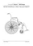
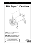
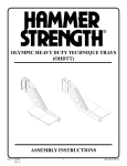
Merits
MP1 series
Service Manual
Nov.3.2006 V1
Index
1. Introduction..............................................................................1
2. Service Guide............................................................................1
2.1
To replace the anti-tipper assembly ...................................................... 1
2.2
To replace the front rigging assembly ................................................. 2
2.3
To replace the armrest assembly ............................................................ 5
2.4
To replace the seat upholstery ................................................................. 6
2.5
To replace the backrest upholstery ....................................................... 6
2.6
To replace the battery folding frame assembly .............................. 7
2.7
To replace the wheel lock assembly ...................................................... 8
2.8
To replace the driven wheel assembly ................................................. 8
2.9
To replace the motor & gearbox assembly ....................................... 9
2.10 To replace the caster assembly .............................................................. 10
2.11 To replace the cross braces assembly ................................................. 11
2.12 To replace the side frame assembly .................................................... 12
The numbers show in this service manual is just for reference. The part
numbers should be in accordance with current exploded chart.
1. Introduction
The purpose of this manual is to provide dealers and/or distributors with the
product information and instructions that are required for servicing the MP1
series power wheelchair.
2. Service Guide
The MP1 power wheelchair consists of two main parts:
n Body assembly
n Electrical system (Please refer to P1 & P2 series for VSI controller service
manual)
The body assembly is composed of the anti-tipper assembly, the front rigging
assembly, the armrest assembly, the seat upholstery, the backrest upholstery, the
battery folding frame assembly, the wheel lock assembly, the driven wheel
assembly, the motor & gearbox assembly, the caster assembly, the cross braces
assembly, the side frame assembly, and so on.
How to replace or repair the body assembly? The steps are as follows.
2.1 To replace the anti-tipper assembly
u When you should replace the anti-tipper assembly?
◇ If the anti-tipper assembly is worn out.
◇ If your power wheelchair can not avoid knocked or bumped cause the
anti-tip wheel is broken.
u How to replace the anti-tipper assembly?
◇ Please proceeding steps as follows if it has to replace.
1. Replace the anti-tipper assembly (1.1) if it is worn out or deformed.
Press these two brass buttons (1.25) and pull out the anti-tipper , and
then replace it.
2. Replace the anti-tip wheel (1.26) if it is worn out or deformed. Use
screwdriver and wrench to loosen the screw (1.29) and nut (1.28) , and
then replace the anti-tip wheel.
1
2.2 To replace the front rigging assembly
u When you should replace the front rigging assembly?
◇ If the front rigging assembly is deformation.
◇ If your power wheelchair can not avoid knocked or bumped cause the
front rigging assembly is deformed.
◇ If the front rigging assembly is out of shape due to an accident.
u How to replace the front rigging assembly?
◇ Please proceeding steps as follows if it has to replace.
1. Replace the footrest assembly if it is worn out or deformed.
A. Hex. tube type
a. Swing out the footrest and take out it from the side frame. Use hex.
tools to loosen the screw (8.09) and then replace the footrest hanger
assembly (8.2) or the footplate & extension tube assembly (8.4) if it
is worn out or deformed.
b. Use screwdriver to loosen the screw (8.14), and remove the bumper
rubber (8.15), footplate (8.11) and spring plate (8.13), and then
replace the footplate (8.11) or extension tube (8.10) if it is worn out
or deformed.
Hex. tube type
B. Round tube type
a. Swing out the footrest and take out it from the side frame. Use hex.
tools to loosen these two screws (8.14) and then replace the footrest
hanger assembly (8.2) or the footplate & extension tube assembly
(8.4) if it is worn out or deformed.
2
b. Use screwdriver to loosen the screw (8.13), and remove the bumper
rubber (8.12), footplate (8.10) and spring plate (8.11), and then
replace the footplate (8.10) or extension tube (8.09) if it is worn out
or deformed.
Round tube type
2. Replace the elevating legrest assembly if it is worn out or deformed.
a. Swing out the elevating legrest and take out it from the side frame.
Use wrench to loosen these two screws (8.48) and then replace the
ratchet assembly (8.9) if it is worn out or deformed.
b. Use screwdriver and wrench to loosen the screw (8.31) and nut (8.32),
and then replace the legrest hanger assembly (8.6) if it is worn out or
deformed.
c. Use wrench to loosen the extension bolt (8.54), and then replace the
legrest pad & bracket & tube assembly (8.8) or footplate & extension
tube assembly (8.1A) if it is worn out or deformed.
d. Use screwdriver to loosen the screw (8.41), and replace the legrest
pad (8.40) if it is broken.
e. Use screwdriver to loosen the screw (8.58), and remove the bumper
rubber (8.57), footplate (8.55) and spring plate (8.56), and then
replace the footplate (8.55) or extension tube (8.51) if it is worn out
or deformed.
3
4
2.3 To replace the armrest assembly
◆
◇
◇
◇
When you should replace the armrest assembly?
If the armrest assembly is worn out.
If the padded armrest pad is pierced or scratched by something.
If the power wheelchair crashed cause the armrest assembly out of
shape.
◆ How to replace the armrest assembly?
◇ Please proceeding steps as follows if it has to replace.
1. Use screwdriver to loosen the screw (2.22 or 2.18) under armrest to
disassemble armrest from armrest support tube. If the padded armrest
pad (2.21 or 2.17) is broken, then replace it.
2. Use hex. tools and wrench to loosen the screw (1.08) and nut (1.05)
from bracket (1.07) on the side frame (see page 14). If the armrest
assembly (2.1) is worn out or deformed, then replace it.
5
2.4 To replace the seat upholstery
u
◇
◇
◇
When you should replace the seat upholstery?
If the seat upholstery is worn out.
If the seat upholstery is pierced or scratched by something.
If the seat upholstery is out of shape due to an accident.
u How to replace the seat upholstery?
◇ Please proceeding steps as follows if it has to replace.
Replace the seat upholstery (4.01) by steps if it is worn out.
a. Use screwdriver to loosen all screws (4.03).
b. Draw out the strips (4.02) from the seat upholstery, and then replace
the seat upholstery.
2.5 To replace the backrest upholstery
u
◇
◇
◇
When you should replace the backrest upholstery?
If the backrest upholstery is worn out.
If the backrest upholstery is pierced or scratched by something.
If the backrest upholstery is out of shape due to an accident.
u How to replace the backrest upholstery?
◇ Please proceeding steps as follows if it has to replace.
Replace the backrest upholstery (4.05) by steps if it is worn out.
a. Use hex. tools to loosen the screw (1.03) on the left & right side
frame (see page 14), then draw out two backrest tube sets (1.3) with
backrest upholstery.
b. Use hex. tools to loosen the screw (4.06), and then replace the
backrest upholstery.
6
2.6 To replace the battery folding frame assembly
u When you should replace the battery folding frame assembly?
◇ If the battery folding frame assembly is deformation.
◇ If your power wheelchair can not avoid knocked or bumped cause the
battery folding frame assembly is deformed.
◇ If the battery folding frame assembly is out of shape due to an accident.
u How to replace the battery folding frame assembly?
◇ Please proceeding steps as follows if it has to replace.
1. Replace the battery box holder assembly (9.1) if it is worn out or
deformed. Pull out these four draw pins (9.14) , and then replace it.
2. Replace the battery box bracket (9.08) if it is worn out or deformed. Use
hex. tools and wrench to loosen the screw (9.15) and nut (9.17), and then
replace it.
7
2.7 To replace the wheel lock assembly
u When you should replace the wheel lock assembly?
◇ If the wheel lock is deformation.
◇ If your power wheelchair can not avoid knocked or bumped cause the
wheel lock assembly is deformed.
◇ If the wheel lock assembly is out of shape due to an accident.
u How to replace the wheel lock assembly?
◇ Please proceeding steps as follows if it has to replace.
Replace the wheel lock assembly (6.2) if it is damaged. Use hex. tools to
loosen the screw (6.13) , then replace it.
2.8 To replace the driven wheel assembly
u When you should replace the driven wheel assembly?
◇ If the driven wheel assembly is worn out.
◇ If the driven wheel assembly is out of shape due to an accident.
◆ How to replace the driven wheel assembly?
◇ Please proceeding steps as follows if it has to replace.
Replace the driven wheel (5.1 or 5.01) by the following steps if it is
worn out or deformed.
a. Remove the hub cap (5.02). (Omit this step without the cap.)
b. Loosen the nut (5.85) and washer (5.87) to replace the driven wheel
assembly.
8
2.9 To replace the motor & gearbox assembly
u
◇
◇
◇
◇
When you should replace the motor & gearbox assembly?
If the motor & gearbox assembly has noise.
If the motor & gearbox assembly can’t drive the power wheelchair.
If the motor & gearbox assembly out of shape due to an accident.
If the motor & gearbox assembly is deformation.
◆ How to replace the motor & gearbox assembly?
◇ Please proceeding steps as follows if it has to replace.
1. Replace the motor & gearbox assembly (5.2) by the following steps if it
has a breakdown.
a. Remove the driven wheel (5.1 or 5.01). (The step is same as 2.8.)
b. Use hex. tools to loosen the screw (5.94 and 5.95), and then replace
the motor & gearbox assembly.
9
2. Replace the motor (5.71) if it has a breakdown. Use hex. tools to loosen
the screw (5.82), and then replace it.
3. Replace the carbon brush (5.72) if it has a breakdown. Use screwdriver
to loosen the carbon brush cap (5.73), and then replace it.
2.10 To replace the caster assembly
◆ When you should replace the caster assembly?
◇ If the caster assembly is worn out.
◇ If the caster assembly is out of shape due to an accident.
◆ How to replace the caster assembly?
◇ Please proceeding steps as follows if it has to replace.
The caster assembly is composed of a front wheel and fork.
1. Replace the caster assembly (5.0 or 7.1) if it is found to be deformed.
Fix the front wheel in place, use wrench to loosen the nut of headset
bearing (5.13 or 7.07) and remove the caster assembly.
2. Replace the front wheel (5.03 or 7.03) by the following steps if it is
worn out or deformed.
a. Hold the screw (5.09 or 7.02) and loosen the nut (5.11 or 7.05) and
then remove the front wheel.
b. If the PU tire (or solid tire) is worn out, then replace it.
PU form (two piece of rims)
10
Solid tire (one piece of rim)
2.11 To replace the cross braces assembly
u When you should replace the cross braces assembly?
◇ If the cross braces assembly is deformation.
◇ If your power wheelchair can not avoid knocked or bumped cause the
cross braces assembly is deformed.
◇ If the cross braces assembly is out of shape due to an accident.
u How to replace the cross braces assembly?
◇ Please proceeding steps as follows if it has to replace.
1. Replace the cross braces assembly (3.1) by steps if it is worn out or
deformed.
a. Remove the seat upholstery (4.1) by step 2.4.
b. Use hex. tools and wrench to loosen the screws (3.10) and nuts (3.16),
and then replace the cross braces assembly.
2. Replace the draw bar (3.12) if it is worn out or deformed. Use hex. tools
and wrench to loosen the screw (3.15) and nut (3.16), and then replace
it.
3. Replace the cross brace (3.01 or 3.02) if it is worn out or deformed. Use
hex. tools and wrench to loosen the screw (3.03) and nut (3.06), and then
replace it.
11
2.12 To replace the side frame assembly
u When you should replace the side frame assembly?
◇ If the side frame assembly is deformation.
◇ If your power wheelchair can not avoid knocked or bumped cause the
side frame assembly is deformed.
◇ If the side frame assembly is out of shape due to an accident.
u How to replace the side frame assembly?
◇ Please proceeding steps as follows if it has to replace.
1. Replace the backrest tube set (1.3) if it is worn out or deformed. (The
step is same as 2.5.)
2. Replace the side frame assembly (1.2) by steps if it is worn out or
deformed.
a. Pull away all power connectors.
12
b. Remove the battery boxes.
c. Remove the anti-tipper assembly (1.1-page 1), the front rigging
assembly (8.1 or 8.5-page 2〜4), the armrest assembly (2.1-page 5),
the seat upholstery (4.1-page 6), the backrest upholstery (4.05-page 6),
the battery folding frame assembly (9.1 & 9.08-page 7), the wheel
lock assembly (6.2-page 8), the driven wheel assembly (5.1 or
5.01-page 8), the motor & gearbox assembly (5.2-page 8〜9), the
caster assembly ( 5.0 or 7.1-page 9) and the cross braces assembly
(3.1-page 11) by step 2.1〜2.11.
d. Check for deformations or cracks on the side frame and replace the
side frame should they exist.
13
14