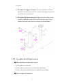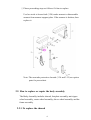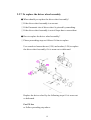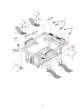
1
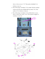
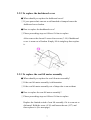
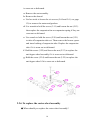
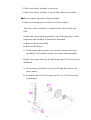
Merits
P301 series
Service Manual
Nov.1.2006 V1
Index
1. Introduction............................................................................1
2. Service guide ...........................................................................1
2.1.
2.2.
How to replace or repair the seat assembly ................................................ 1
2.1.1.
To replace the seat body ................................................................................... 1
2.1.2.
To replace the seat base plate assembly ............................................................ 2
2.1.3.
To replace the seat post assembly ..................................................................... 2
2.1.4.
To replace the left/right armrest ........................................................................ 3
How to replace or repair the body assembly .............................................. 4
2.2.1.
To replace the shroud ....................................................................................... 4
2.2.2.
To replace the dashboard cover......................................................................... 7
2.2.3.
To replace the seat lift motor assembly ............................................................. 7
2.2.4.
To replace the footplate assembly ..................................................................... 8
2.2.5.
To replace the anti-tipper wheel assembly ........................................................ 9
2.2.6.
To replace the caster wheel assembly.............................................................. 10
2.2.7.
To replace the driver wheel assembly ............................................................. 12
2.2.8.
To replace the frame assembly........................................................................ 13
The numbers shown in this service manual is just for reference. The part
numbers should be in accordance with current exploded drawing.
1. Introduction
The purpose of this manual is to provide dealers and/or distributors with
the product information and instructions that are required for servicing the
P301 powerchair.
2. Service guide
The P301 powerchair consists of three main parts:
n Seat assembly
n Body assembly
n Electrical system (Please refer to P3/P7 series Shark or VR2 service
manual)
2.1. How to replace or repair the seat assembly
The seat assembly includes the seat body, the seat base plate assembly,
the seat post assembly and the left/right armrest.
2.1.1. To replace the seat body
◆ When should you replace the seat body?
◇ If the seat body is worn out.
◇ If the seat body is pierced or scratched by something.
◇ If the powerchair crashed cause the seat body out of shape.
◆ How to replace the seat body?
◇ Please proceeding steps as follows if it has to replace.
Replace the seat body by the following steps if it is broken.
a. Pull the swivel lever (4.44) under the seat up to unlock it and
rotate the seat a little bit to the position where you can feel the
seat rotate freely. Pull the seat upward. (See next page)
b. Use hex tools to loosen four pieces hex fixed bolt (4.50) on
seat base plate assembly and remove the seat body from the
1
seat base plate assembly if it is broken. (See next page)
2.1.2. To replace the seat base plate assembly
◆ When should you replace the seat base plate assembly?
◇ If the seat base plate is deformation.
◇ If the seat base plate out of shape due to an accident.
◆ How to replace the seat base plate assembly?
◇ Please proceeding steps as follows if it has to replace.
Follow preceding step of 2.1.1. You can remove seat base plate
assembly too if it is worn out or deformed.
2.1.3. To replace the seat post assembly
◆ When should you replace the seat post assembly?
◇ If the seat post is deformation.
◇ If the seat post out of shape due to an accident.
◆ How to replace the seat post assembly?
◇ Please proceeding steps as follows if it has to replace.
The seat post assembly includes the upper seat post and the lower
2
seat post.
a. To replace the upper seat post: Use two wrenches to loosen
the nut (4.18) and screw (4.17) to remove the upper seat post if
it is worn out or deformed.
b. To replace the lower seat post: Repeat step of a. then use the
wrench to hold the screw (4.12) and loosen the nut (4.14) to
remove the lower seat post if it is worn out or deformed.
2.1.4. To replace the left/right armrest
◆ When should you replace the armrest?
◇ If the armrest is worn out.
◇ If the armrest is pierced or scratched by something.
◇ If the powerchair crashed cause the armrest out of shape.
◆ How to replace the armrest?
3
◇ Please proceeding steps as follows if it has to replace.
Use hex tools to loosen bolt (3.28) under armrest to disassemble
armrest from armrest support plate. If the armrest is broken, then
replace it.
Note: The arm tube protective shrouds (3.34 and 3.35) are option
parts for powerchair.
2.2. How to replace or repair the body assembly
The Body Assembly includes shroud, footplate assembly, anti-tipper
wheel assembly, caster wheel assembly, driver wheel assembly and the
frame assembly.
2.2.1. To replace the shroud
4
◆ When should you replace the shroud?
◇ If your powerchair can not avoid knocked or bumped cause the
shroud broken.
◆ How to replace the shroud?
◇ Please proceeding steps as follows if it has to replace.
For general powerchair
Check for deformations or cracks on the shroud. Simply lift the
shroud straight up then replace it.
For full light powerchair
Check for deformations or cracks on the shroud.
Replace the shroud by the following steps if it is deformed or
broken.
a. Remove the seat assembly.
b. Simply lift the shroud straight up carefully.
c. Take off the plug (3.37) under cover of the shroud. (See next
page)
d. Take off the plug of headlight (3.29) by hand and use a screw
5
driver to loosen screw (3.31). Then replace headlight if it is
broken or worn out.
e. Take off the plug of turnlight (3.32) by hand. Hold the turnlight
in place and rotate the turnlight holder by hand (3.28). Then
replace it if it is broken or worn out.
e. Take off the plug of rearlight (3.33) by hand and use a screw
driver to loosen two screws (3.35). Then replace rearlight if it
is broken or worn out.
3.37
6
2.2.2. To replace the dashboard cover
◆ When should you replace the dashboard cover?
◇ If your powerchair can not avoid knocked or bumped cause the
dashboard cover broken.
◆ How to replace the dashboard cover?
◇ Please proceeding steps as follows if it has to replace.
After remove the shroud. Loosen four screws (3.14) if dashboard
cover is wron out of broken. Simply lift it straight up then replace
it.
2.2.3. To replace the seat lift motor assembly
◆ When should you replace the seat lift motor assembly?
◇ If the seat lift motor assembly is deformation.
◇ If the seat lift motor assembly out of shape due to an accident.
◆ How to replace the seat lift motor assembly?
◇ Please proceeding steps as follows if it has to replace.
Replace the limited switch of seat lift assembly if it is worn out or
deformed. Hold the screw (4.36) and loosen the nut (4.37) and
then replace it. (See next page)
7
Replace the seat lift motor assembly by following steps if it is
worn out or deformed.
a. Remove the seat assembly.
b. Remove the shroud.
c. Use hex tools to loosen three bolts (4.39) first.
d. Hold the screw (4.31) under the frame and loosen the nut (4.32)
and then replace seat lift motor assembly if it is worn out or
deformed.
2.2.4. To replace the footplate assembly
◆ When should you replace the footplate assembly?
◇ If the footplate assembly is deformation.
◇ If the footplate assembly out of shape due to an accident.
8
◆ How to replace the footplate assembly?
◇ Please proceeding steps as follows if it has to replace.
Replace the footplate assembly if it is worn out or deformed. Hold
the screw (8.07) and loosen the nut (8.08) and then replace the
footplate assembly.
Hole the screw (8.03) and loosen the nut (8.10) then remove the
footplate. If the footplate is worn out, then replace it.
2.2.5. To replace the anti-tipper wheel assembly
◆ When should you replace the anti-tipper wheel assembly?
◇ If the anti-tipper wheel assembly is worn out.
◇ If your powerchair can not avoid knocked or bumped cause the
anti-tipper wheel broken.
◆ How to replace the anti-tipper wheel assembly?
◇ Please proceeding steps as follows if it has to replace.
The anti-tipper wheel assembly includes the suspension bar,
suspension spring, suspension tube set, anti-tipper extension tube
and anti-tipper wheel.
Replace the anti-tipper wheel assembly by the following steps if it
9
is worn out or deformed.
a. Remove the seat assembly.
b. Remove the shroud.
c. Use hex tools to loosen the six screws (5.60 and 5.61, see page
12) to remove the motor and gearbox.
d. Use wrench to hold the screw (2.11) and loosen the nut (2.12)
then replace the suspension bar or suspension spring if they are
worn out or deformed.
e. Use wrench to hold the screw (2.20) and loosen the nut (2.21)
to take off suspension tube set. Then remove the bronze spacer
and inner bushing of suspension tube. Replace the suspension
tube if it is worn out or deformed.
f. Hold the screw (2.22) and loosen the nut (2.23) to replace the
anti-tipper wheel assembly if it is worn out or deformed.
g. Hold the screw (2.24) and loosen the nut (2.25) to replace the
anti-tipper wheel if it is worn out or deformed.
2.2.6. To replace the caster wheel assembly
◆ When should you replace the caster wheel assembly?
10
◇ If the caster wheel assembly is worn out.
◇ If the caster wheel assembly is out of shape due to an accident.
◆ How to replace the caster wheel assembly?
◇ Please proceeding steps as follows if it has to replace.
The caster wheel assembly is composed of a caster wheel and
fork.
Replace the caster wheel assembly by the following steps if, after
inspection, the assembly is found to be deformed.
a. Remove the seat assembly.
b. Remove the shroud.
c. Fix the caster wheel in place, use wrench to loosen the nut of
assembly (6.24) and then remove the caster wheel assembly.
Replace the caster wheel by the following steps if it is worn out or
deformed.
a. Use wrench to loosen two screws (6.22) and then remove the
caster wheel.
b. Loosen the nuts (6.15) to replace the PU tire. If it is worn out
or deformed.
11
2.2.7. To replace the driver wheel assembly
◆ When should you replace the driver wheel assembly?
◇ If the driver wheel assembly is worn out.
◇ If the Pneumatic tire of driver wheel is pierced by something.
◇ If the driver wheel assembly is out of shape due to an accident.
◆ How to replace the driver wheel assembly?
◇ Please proceeding steps as follows if it has to replace.
Use wrench to loosen the nut (5.59) and washer (5.58) to replace
the driver wheel assembly if it is worn out or deformed.
Replace the driver wheel by the following steps if it is worn out
or deformed.
For PU tire
a. Follow preceding step above.
12
b. If the PU tire is worn out. Use hex tools to loosen eight screws
(6.78) to replace it. (See next page)
For Pneumatic tire
a. Loosen the cap (6.79) by hand to remove it.
b. Use a pointed material to release gas of tube valve (6.74) first.
c. Use hex tools to loosen the eight screws (6.78) to replace tire or
tube if they are worn out or broken.
2.2.8. To replace the frame assembly
◆ When should you replace the frame?
13
◇ If the frame is deformation.
◇ If your powerchair can not avoid knocked or bumped cause the
frame deform.
◇ If the frame is out of shape due to an accident.
◆ How to replace the frame?
◇ Please proceeding steps as follows if it has to replace.
Check the whole body assembly by the following steps if there is
noise or sticking motion during operation of the powerchair.
a. Remove the seat assembly, the shroud, dashboard cover, the
seat post/lift assembly, the footplate assembly, anti-tipper
wheel assembly and the caster wheel assembly by step 2.1 and
2.2.1 until 2.26.
b. Use hex tools to loosen six pieces the screw (5.60 and 5.61) to
remove motor and gearbox assembly. (See page 12)
c. Use screw driver to hold the screw (1.21) and loosen the nut
(1.22) to remove controller. (See next page)
d. Check for deformations or cracks on the frame and replace the
frame should they exist.
14
n
15