1
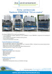
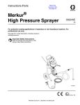
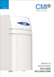
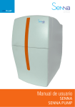
INSTRUCTION MANUAL
SINTRA
PRESSURE TANK CS
POSITIION
DESCRIPTION
CODE
1
2
3
4
5
6
7
8
9
10
11
12
13
14
15
16
17
18
19
20
21
22
23
24
25
26
27
28
29
30
31
32
33
34
35
36
37
38
39
40
41
42
43
44
45
46
47
48
49
50
51
52
53
54
55
56
57
58
262702
771600
274700
294600
275700
658300
292900
291604
291803
280400
291902
274400
263800
263600
274600
652401
275400
294801
294100
282800
653703
281600
278800
281700
279000
296800
292500
264700
281000
265000
264901
295204
272400
272000 / 272100
276800
276900
282400
282500
295800
267700
274500
276200
295202
294200
267500
764402
293500
764402
274000
743303
SINTRA lower cover (white)
10L pressure tank
Leaking sensor
JACO elbow thread 1/4"- tube 3/8"
JACO elbow thread 1/8"- tube 1/4" with SS check valve
JACP tee 1/4"-1/4"-1/4"
SINTRA metallic frame
PJK-260 electronic board
SINTRA upper cover (white)
2012 membrane housing
GAC-Ag post-filter
SINTRA rear cover (white)
CS 5mm sediment filter
3/8"-1/4" QC reducing elbow
CS GAC filter
SINTRA front cover (white)
SINTRA upper front cover (orange)
SINTRA buttons
SINTRA front cover (orange)
JACO elbow thread 1/8"- tube 1/4"
Tank valve 3/8"
Elbowed adaptor for tank valve 3/8"
JACO elbow thread 3/8"- tube 1/4"
Flushing solenoid valve 24V
JACO male run tee thread 1/4"-tube 1/4"
Inlet solenoid valve 24V
Minimum pressure switch
QC tee 3/8"-1/4"-3/8"
Display electronical board
QC bulkhead 1/4"
QC stem elbow 1/4"
QC bulkhead 3/8"
QC stem elbow 3/8"
Robin faucet
75 GPD RO membrane
1/4" drain clamp
Faucet female adapter thread 7/16"-tube 3/8"
Ball valve 1/4"
Free nut 3/8"-3/8" wall adaptor, drill 1/4"
Transformer 220-24V
White 3/8" polyethylene tube
White/Blue 1/4" polyethylene tube
Insert 1/4"
Insert 3/8"
Locking clip 1/4"
Locking clip 3/8"
Electronic board box
Double mounting clip 2 1/2"
JACO elbow thread 1/4"- tube 1/4"
Double male connector 1/4"
Bulkhead for power supply
Maximal pressure switch 20-40 PSI
Single mounting clip 2 1/2"
Base double mounting clip 2 1/2"
UP-7000 pump 24V
Base double mounting clip 2"
JACO straight male conector pipe 1/4"-tube 1/4" (BLUE)
Higienization kit
SINTRA COMPONENTS DESCRIPTION
e
d
o
k
a
n
j
i
h
g
l
a
b
c
d
e
f
g
h
i
j
k
l
m
n
o
Minimum pressure switch
Inlet solenoid valve 24V
Flushing solenoid valve 24V
CS 5mm sediment filter
CS GAC filter
UP-7000 pump 24V
75 GPD RO membrane
Maximal pressure switch 20-40 PSI
Tank valve 3/8"
10L pressure tank
GAC-Ag post-filter
Leaking sensor
PJK-260 electronic board
Quality probe
Display electronical board
e
d
k
m
a
g
j
f
c
b
SANITIZING KIT
PDA
FCT
TRANSFORMER
ECOLOGICAL
DIRECT ACCESS
AQUASTOP
CLICK
QUALITY CONTROL
JOHN GUEST
LOGICAL
FILMTEC
Portable programmer.
Configurable feature and parameters.
Sanitization Kit for domestic osmosis.
00:00:00
External transformer
Automatic warning system
for filter change
Easy maintenance. Direct access.
Control system for a reduced
water consumption.
Safe binding and locking
of connections.
Automatic leak detector.
Water quality control.
High quality components . NSF certified.
Configuration acording
to the water quality.
DOUBLE FLOW
Easy and fast filling system.
High quality membrane DOW CHEMICAL.
NSF certified.
Ag
Plata
SILVER
Gac silver carbon. NSF certified.
CALGON CARBON
GREEN FILTER CS
AUTO FLUSHING
INSERT
The content of the filters i made by
CALGON (USA). NSF-Quality certified.
Automatic membrane membrane,
ELECTROVALVE
Electrovalve with safety filter.
New top security filter and
easy maintenance.
Safety system for tube connections.
Contents
Página
01. PRESENTATION
2
02. INTRODUCTION
2
02.1 What is natural osmosis and reverse osmosis?
02
02.2 How does the membrane of your system work?
3
02.3 Concentration of salt and other substances reduced by its reverse osmosis membrane
3
02.4 The effect of pressure and temperature in a reverse osmosis system
3
02.5 The effect of a concentration of sales in the feed water
4
03. TECHNICAL CHARACTERISTICS
5
04. UNPACKING AND VERIFCATION OF CONTENT
5
05. PRE-WARNINGS
6
05.1 Conditions for the proper working of the equipment
06 6
05.2 Installation of the equipment
6
05.3 Operation and maintenance
6
05.4 Use of equipment
7
05.5 Recommendations for the proper use of the osmosis water
7
06. INSTALLATION OF THE SYSTEM
8
06.1 Step by step installation0
9
07. START-UP AND HYGIENISATION
12
08. WORKING OF THE SINTRA EQUIPMENT
16
08.1 Description of Operation
016
08.2 Interface with the user
17
09. MAINTENANCE / CONSUMABLES
18
09.1 Maintenance
18
09.2 Hygienisation
21
10. GUIDE FOR THE IDENTIFICATION AND RESOLUTION OF PROBLEMS
22
11. MAINTENANCE SERVICE MANUAL
24
12. EC STATEMENT
Interior cover
13. GUARANTEE
Interior cover
14. INSTALLATION SHEET AND PUTTING INTO OPERATION OF THE SYSTEM
Back flap
1
1. Presentation
2. Introduction
1. PRESENTATION
2. INTRODUCTION
Welcome to your reverse osmosis SINTRA system. Thank you
and congratulations. You have made a great choice in chosing
the reverse osmosis SINTRA Series system.
The SINTRA series systems are some of the best domestic
appliances for the improvement of the characteristics of water
that you can find on the market.
The quality of the water in our environment is getting worse
every day. The reality of this is what has driven us to design
and manufacture this domestic osmosis system in order to
make water of the highest quality available to you.
Your SINTRA Series system provides you with different benefits and advantages:
The SINTRA Series system provide you with a better quality
of life.
You will perceive an improvement in the taste of your drinking
water, and likewise in the taste of your coffees, juices or icecubes. Cooking with the purified water will heighten the taste
of the food. Your family will have healthier water.
The water provided is water that has a LOW MINERAL CONTENT. Osmotizad water helps prolong the life of your domestic appliances and is ideal for steam irons, coffee makers and
humidifiers.
• It is a physical system that does not use or add
chemical products to the water.
• Provides high quality water.
• Ensures high production.
• Has low maintenance costs.
• Convenient and easy installation.
It is important that you keep and read this manual carefully before the
installation and operation of the system.
Should you have any queries about the use, installation or maintenance of
this system, please contact the technical assistance service (T.A.S.) at your
distributor.
2.1 What is natural osmosis and reverse
osmosis?
Natural osmosis or direct osmosis is the most common in
nature, as a semi-permeable membranes make up part of
the majority of organism (for instance, plant roots, organs in
our body, cellular membranes etc.)
When two solutions with different concentrations of salts
are separated by a semi-permeable membrane, there is,
naturally, a flow of water from the solution that has a lower
concentration of salts to that of higher concentration. It is
necessary to apply sufficient pressure, of the water with a
higher concentration, against the membrane, in order to stop
this tendency and natural flow of the system. This process is
called reverse osmosis.
At present, reverse osmosis is the best method to produce pure water via a physical system (without using chemical
products).
As has been explained, its working principle is based on the
same as that of our own organism, where water is distributed
by natural osmosis.
The human body is mainly made up of water:
Woman> 55 – 65 %
Man
> 65 – 75 %
Child
> 80 %
An adult body contains between 38 and 48 litres of water,
30% of which is found in the cells. This water in the body,
which is almost completely recycled every 15 days, is the
basis for the transportation of nutrients, oxygen to cells, the
elimination of waste and it controls the body temperature.
2
2. Introduction
We consume an average of 2.2 litres of water per day, including the water found in foods.
2.2 How does the membrane of your system
work?
FEED WATER
FEED PRESURE
Membrane
The water that is going to be purified exerts pressure on the
semi-permeable membrane, to the extent that part of the
same is able to pass through the pores of the membrane
(osmosis water), while the remainder of the water (rejected
water or that with high concentrations of salt) are diverted to
the drainpipe.
Given that the diameter of the membrane pores are less
than 0.0001 microns, only the water molecules and a certain
amount of minerals (sodium, potassium, magnesium etc.) are
able to get through, eliminating the excess minerals that our
body does not need, as well as the bacteria, heavy metals,
pesticides, chemical products, etc.
The chemical composition and concentration of salts and
other substances of the water on entering the reverse osmosis
system has an affect on the purified water.
The TFC reverse osmosis membrane of your SINTRA Series
system can reduce the concentration of the elements and
compounds, among others, outlined in the following tables.
Inorganic
ELEMENT/COMPOUND
SODIUM
CALCIUM
MAGNESIUM
ALUMINIUM
COPPER
NICKEL
ZINC
BARIUM
CARBONATES
CHLORINE
BICARBONATES
NITRATES
PHOSPHATES
FLUORIDE
CYANIDE
SULPHATES
BORON
ARSENIC
REDUCTION
90-95%
93-98%
93-98%
93-98%
93-98%
93-98%
93-98%
93-98%
93-98%
90-95%
90-95%
45-55%
93-98%
93-98%
90-95%
90-95%
40-45%
93-98%
PURE WATER
Organic
REJECTION
DIAMETRE OF
RO MEMBRANE
0.0001 μm PORE
2.3 Concentration of salts and other substances
reduced by the reverse osmosis membrane
DIAMETRE OF
5 µm FILTER
DIAMETRE OF
1 µm FILTER
SIZE OF
BACTERIA
SIZE OF
A VIRUS
ELEMENT/COMPOUND
HUMIC ACIDS
GLUCOSE
ACETONE
ISOPROPANOL
ETHYLBENZENE
ETHYPHENOL
TETRACHLORETHYLENE
UREA
1,2,4 TRICHLOROBENZE
1,1,1,TRICHLOROTHANE
REDUCTION
98%
98-99%
70%
90%
71%
84%
68-80%
70%
96%
98%
2.4 The effect of pressure and temperature in a
reverse osmosis system
The membrane usually rejects more than 95% of salts, however
the percentage may vary depending on the quality of the water,
the temperature and pressure.
3
2. Introduction
Conversion factors
2.5 Effect of the concentration of salts in the feed
water
BY PRESSURE
PRESSURE (BARS)
0,70
1,00
1,50
1,75
2,50
4,00
4,50
4,90
5,20
5,80
CONVERSION FACTOR
ON PRODUCTION
0,70
0,25
0,33
0,42
0,58
1,00
1,08
1,17
1,25
1,42
REJECTION OF SALTS
84
88
90
92
93
95
95
95
95
95
BY TEMPERATURE
CONVERSION FACTOR
TEMPERATURE (ºC)
ON PRODUCTION
6
0,38
8
0,45
10
0,52
12
0,59
14
0,66
16
0,70
18
0,77
20
0,85
22
0,88
25
1,00
28
1,09
30
1,16
32
1,23
34
1,30
80 – 90% > MEDIUM QUALITY
70 – 80% > LOW QUALITY
Below 70% the life of the membrane is finished. Using a conductivity metre or a TDS measurer compares the conductivity
of the feed water with that which comes out of the membrane
and obtains the percentage of rejection of salts.
4
Conductivity of R.O. water
Conductivity of feed water
MAXIMUM TDS
OF FEED*
MINIMUM PRESSURE OF
FEED TO MEMBRANE**
Up to 200 μm
3,5 bars
between 200 and 500 μm
3,8 bars
between 500 and 800 μm
4,0 bars
between 800 and 1200 μm
4,3 bars
between 1200 and 1500 μm
4,5 bars
between 1500 and 1800 μm
4,75 bars
between 1800 and 2000 μm
5,2 bars
counter-pressure, a hardness of 15 °F and corrected salinity with NaCl.
** The pressure shown is calculated for a production of 61/h.
90 – 95% > MAXIMUM QUALITY
(-
Table of pressure in relation to the TDS
** The test is carried out with a 50 GPD membrane at 14 °C, without
The life of the membrane is evaluated by the percentage of
salts rejected.
Rejection of salts % = 1
The concentration of salts and substances in the water to be
treated influences the capacity of the production of osmosis
water by the system, to such an extent that the greater the
concentration of salts in the water to be treated, the greater
the pressure that is necessary against the membrane in order
to exceed the natural osmotic pressure and to guarantee a
minimum flow of osmosis water.
) x 100
3. Technical characteristics
3. TECHNICAL CHARACTERISTICS
CHARACTERISTICS OF SINTRA MODEL
DIMENSIONS (height x width x depth): 400mm x 250mm x 430mm.
WEIGHT: 14 kg.
FEED TEMPERATURE (maximum / minimum in °C): 40ºC / 2ºC.
TDS FEED (maximum): 2000**ppm.
FEED pressure (maximum / minimum): 2.5 / 1 bars. (100-250 kPa.)
NOMINAL PRODUCTION: 200 LPD**.
MEMBRANE: Type 1 x 1812 75.
MEMBRANE PRODUCTION: 75 GPD*.
Softened water with 250 ppm. T: 25 ºC. 15% conversion
Pressure against membrane: 3.4 bars (without counter-pressure).
PUMP: Booster.
MAX ACCUMULATION. (pre-charged tank at 7 PSI): 5’5 litres.
ELECTRIC CURRENT: 24 Vdc. 48 W.
ELECTRIC ADAPTOR: 100-240V. 50/60 Hz. 24 Vdc 1’25 A
MANUFACTURER: Manufactured by PURICOM WATER IND. CORP.
(Taiwan) for: PURICOM EUROPA. Pol. Ind. L’Ametlla Park. C/Aiguafreda 8.
08480 L’Ametlla de Vallès. Barcelona. España.
T+34 902 305 310. F+34 936 934 329.
* Levels may vary some +/– 20%.
** For salinity up to 2000 ppm, consult the pressure table in relation to the TDS in
section 2 of the present manual. For salinity above 2000 ppm, first consult your distributor. See section 5 WARNINGS.
4. Unpacking and verification of contents
4. UNPACKING AND VERIFICATION OF CONTENTS
It is important that prior to installing and starting the system you
check the box and condition of the system with the objective
of guaranteeing that it has not been damaged during transport. Any claims for damages during transport must be
presented together with the delivery note or invoice to
the distributor, including the name of the carrier, within a
period of 24 hours following the reception of the goods.
Remove the system and accessories from their carton packaging; take away the protective packaging.
Throw the plastic bags away or keep them away from children as
they may cause them harm.
You shall find the following sets and elements:
COMPONENT
*
Domestic osmosis system
AMOUNT
1
Faucet + Assembly accessory kit
(34)
1
Kit for drain connection
(36)
1
Wall adaptor for socket
(39)
1
Blue manual ¼” inlet valve
(38)
1
Power supply and cable connection
(40)
1
SINTRA Instructions manual
1
Blue ¼” tube for drain connection
(42)
150 cm
White ¼” tube feed and faucet connector
(41)
300 cm
Reverse osmosis membrane 75 GPD
(35)
1
Membrane housing wrench
(49)
1
* No. of parts on flap.
The packaging material can be recycled and must be thrown
away in the appropriate selective recycling bins or the specific
centre for the collection of waste material. The machine that you
have acquired has been designed and manufactured with high
quality materials and components that can be recycled and reused. This product must not be thrown away into the usual urban rubbish bins. When you want to throw the machine away, it
must be taken to a specific local centre for the collection of materials, stating that it has electric and electronic components.
In order to obtain more information about how to dispose of
your electrical and electronic machine once they have fulfilled
their use, contact the local authorities, the management of urban waste service or the establishment from which you acquired the machine.
The proper collection and treatment of the machines that can
no longer be used contributes to the preservation of natural
resources and also to avoiding potential public health risks.
5
5. Pre-warnings
5. PRE-WARNINGS
The domestic systems of the SINTRA series, ARE NOT POTABILIZATION SYSTEM.
Should the water to be treated come from a public water supply (and as such
complies with the legislation in force RD 140/2003), the domestic systems
of the SINTRA series, significantly improve the quality of the water. agua.
Should the water to be treated not come from a public water
supply, that is, from an unknown source, a physical-chemical and
bacterial analysis of the water shall be necessary, with the objective of
ensuring its proper purification applying the proper techniques and systems appropriate for each case, PRIOR TO THE INSTALLATION of the
system.
Contact your distributor in order to obtain advice about the most appropriate treatment for you.
The FT-Line series systems help you to find the most appropriate pretreatment. Contact your distributor for more information.
FT Line PRE
Ref.: 795407. For the pre-treatment of domestic osmosis.
5.1 Conditions for the proper working of the
system
• Do not use hot water in the system (T > 40 ºC).
• The room temperature must be between 4 ºC and 45 ºC.
• The SINTRA series system incorporates a pump. Should
the pressure system be superior to 3 bars, a safety valve
should be attached prior to water entering the system, set at a
maximum pressure of 2.5 bars. (Ref. 577603).
• For water with salinity higher than 2000 ppm contact your
distributor.
• It is recommended that you decalcify the water to be treated
or that it has a maximum hardness of 15 ºF in order to obtain
the optimum performance of the system.
• Should the water to be treated have a level of hardness superior to 15 F, the life of the membrane may be reduced and
also the performance of the system. It is recommended that
you brush the membrane for 15 seconds once a day (Read
section 9.3 Flushing, which describes how this should be carried out).
• Should the water to be treated contain:
· high concentrations of iron and magnesium (superior to
1ppm on average in the rejection of the machinery),
· prolonged hypochlorisations.
· sludge or turbidity superior to 3 NTUs,
· a concentration of nitrates superior to 100 pmm.
· a concentration of sulphates superior to 250 pmm,
contact your distributor so that they can recommend the
most appropriate pre-treatment for you, and as such ensure
the proper working of the machine so as to avoid damage to
components and guarantee the quality of the water supplied.
6
FT Line 82. Ref.: 795500. 5 μm filtration.
FT Line 83. Ref.: 795501. Activated carbon GAC.
FT Line 85. Ref.: 795503. Cationic resins for decalcification.
FT Line 87. Ref.: 795502. Regulation of pH and remineralisation of
acidic water.
FT Line 88. Ref.: 795504. Granulated carbon active GAC with silver.
FT Line 89. Ref.: 795505. Mixed resin base for demineralisation.
FT Line 90. Ref.: 795506. Granulated carbon active GAC with silver
and silico-phosate.
5. 2 Installation of the system
• Should it be necessary to condition the installation of the home
in order to install the system in the foreseen location, it must be
carried out in accordance with the RIW (Basic rules for the interior installation of water supplies) UNE 149201 (dimensioning
of the water installation for human consumption within buildings)
and acording to national regulation in force.
• The SINTRA series system requires an electrical socket that
is at least 1 metre away.
5. Pre-warnings
• The location foreseen for its installation must have sufficient
space for the machine itself, its accessories, connections, and
to carry out maintenance comfortably.
• Under no circumstances must the system be installed without a cover.
• The systems should not be installed next to a heat source or
where it receives a direct flow of hot air (dryer, refrigerator, etc.)
• The surroundings and setting where the system and tap are
to be installed must meet appropriate hygiene-sanitary conditions.
• Avoid external drips from pipes, drains etc. onto the machi-
• Special attention must be paid to the regular cleaning and
hygiene of the faucet of the osmosis system, and especially
during the periodic maintenance. Use the Oxibac spray (Ref.
65220) for this and disposable kitchen paper or a multiuse
cloth for cleaning the kitchen.
Special attention must be paid to the regular cleaning and hygiene of the faucet of the osmosis system, and especially during the
periodic maintenance. Use the Oxibac spray (Ref. 65220) for this and
disposable kitchen paper.
Under no circumstances must you use a hand towel or a multiuse cloth
for cleaning the kitchen.
nery.
5.3 Start-up and maintenance
• The SINTRA systems, needs to undergo periodic maintenance carried out by qualified technical personnel, with the
objective of guaranteeing the quality of the water produced
and supplied.
• The consumable elements must be substituted with the
frequency indicated by the manufacturer (See section 9.
Maintenance).
.• The system must be hygienised periodically and prior to
its start up.
• Following the start up, the first two deposits must be thrown
away.
• The system must be maintained by qualified technical personnel, carried out under the proper hygienic conditions, with
the objective of reducing the risk of internal contamination of
the machine and its hydraulic system. (For more information
contact the technical service of your distributor).
5.5 Recommendations for the proper use of the
osmosised water
• If you want to feed any other consumption point with osmosis water (such as a fridge with an ice-cube dispenser, another
faucet, etc.), the piping should not be done with a metal tube,
as this will give the water a bad taste. Use a similar plastic tube
(Ref. 272000).
• The water supplied by the domestic osmosis systems has
a LOW SALT CONTENT. The mineral salts required by the human body are provided by food, especially by dairy products
and to a lesser degree by the water we drink.
• We recommended that you do not use aluminum utensils for
cooking with osmosised water.
5.4 Use of the system
• When you are going to be away from home for more than a
week close the water inlet, empty it and disconnect the electric current. On your return connect the electric current of the
same, open the inlet and empty the reservoir tank twice before
consuming the water.
• Following a prolonged period (more than a month) during
which the system has not been in operation or produced
water, contact your distributer in order to carry out the proper
hygienisation and maintenance.
• In order to improve the performance of the system, extract
full jugs and bottles and avoid the occasional extraction of
glasses of water.
7
6. Installation of the system
6. INSTALLATION OF THE SYSTEM
The installation of your SINTRA osmosis system must be carried out by qualified personnel from an authorised technical
service. Follow the recommendations in Section 5 of this manual.
Given that the apparatus that you are going to install improves the quality of the water that you are going to consume and is considered a food, all of the tools that you
are going to use for the assembly and installation must
be clean and under no circumstances contaminated or
impregnated with grease, oils or rust. The work must be
carried out under adequate hygienic conditions, taking the
necessary precautions with everything related to the materials that are going to be in contact with the water to be
treated or consumed. (For more information contact the
distributor).
The most usual place for the installation of the system is under
the sink in the kitchen or in a cupboard next to it.
TOOLS FOR INSTALLATION
MAINTAINANCE AND START-UP OPERATION
TOOL
REFERENCE
-
1
Vice grip pliers
-
2
Drill
-
3
12 and 6 mm drill bits
-
4
652103
5
-
6
No. 2 Allen wrench
No. 14/15mm double socket wrench
-
7
Wheel support for compact system
795800
8
Hygienising hand gel
900117
9
-
10
Teflon tape
Cutter
-
11
206601
12
205200 + 277100
13
Portable pressure measurer
268100
14
Portable conductivity measurer
267900
15
Chlorine analyser
271700
16
Connectors quick disassembly wrench
289200
17
Oxibec spray
652200
18
Hygienisation kit
743303
Membrane housing wrench
filter housings + 2 x ¼ connections
CONTENTS: test holder, gloves, 2.5ml syringe, paper towels,
19
Jar for mixing and OSMOBAC disinfectant
Hand metre
270700
20
RS-232 interface PC connection
761900
21
Portable model PC connection
653105
Contact your distributor for further information.
8
2
3
4
5
6
7
8
9
10
11
12
13
14
15
16
17
18
19
20
21
IMAGE
Adjustable wrench
Edible glycerine
1
6. Installation of the system
6.1 Step by step installation
1. Once it has been decided whether to put the tap on the
counter top or sink (usually in the corner), a hole is drilled in
the same with the 12mm bit, to pass the threaded connecting
pipe through Image 22.
Use the metal escutcheon to choose the location of the drill.
If the metal escutcheon of the tap creates any difficulty in its
assembly due to the geometrics of the counter-top or fridge,
use the rubber joint supplied instead of the metal escutcheon
in order to assemble the tap.
22
24
26
25
CLOSED
27
23
Choose the bit and the type of drill that is appropriate for the material in question.
2. Prior to this, insert the metal escutcheon and a thick flat
rubber joint into the connecting pipe (these must be on the
upper part of the counter-top).
Then pass the threaded connecting pipe through the hole.
Once this is done it is, on the bottom end of the connecting
pipe you connect: the rigid plastic washer, the grower washer
and the hexagonal nut. They should be tightened together
with the No. 14/15mm square wrench, until the tap is completely static and properly positioned. The tap will be positioned as required after the final tightening (it is recommended
that the tap handle is orientated towards the exterior of the
counter top). Image 23.
If the counter-top is thicker than that of the connecting pipe of
the tap, you can use the tap extension (Ref. 261900).
4. Following this you should make the hydraulic connection of
the apparatus to the network. As the system is under pressure
the stopcock situated in the cold water outlet must be closed.
Image 26. Depending on how old the installation is, there may
be no right angle valve and that it is necessary to turn off the
general stopcock in the home. Immediately afterwards, depressurise the installation by turning on the tap of the sink and
wait until water stops coming out of it.
3. Connect the faucet to the permeated water line using the special female adapter (#37), Image 24. Interconnection with the system will be made using 3/8” white pipe (#41), as showed in image
25.
In order to carry out all of the connections use a longer tube, so as to
facilitate the movement of the system once installed and to not unnecessarily disconnect or make access to the same more difficult.
9
6. Installation of the system
Make sure that the connection to the apparatus is going to be carried out in the cold water pipe connection. If the connection is
made in the hot water pipe it may damage important components of the
system. (Generally the cold water pipe connection is found to the right).
Unscrew the connection of the hose or the flexible pipe, image
28. Have a recipient or cloth ready to collect or wipe up the
water that may come out of the flexible pipe when you unscrew it. Insert it into the connection in the wall and the valve or
flexible pipe to the ½” wall adaptor, part No. 39 on flap.
The ½” flat joint that is inserted makes it unnecessary to use a
sealant. (Teflon wire, liquid Teflon, hemp twine, etc.), image 29.
Assemble the ¼ manual in-let valve, part No.38 on flap in the
lateral hole of the wall adapter. Image 30.
28
part No. 39 on flap
29
part No. 38 on flap
30
CLOSED
OPEN
To ensure the proper installation and water-tightness of the
connections made, open the right angle entry valve (or where
applicable the general stopcock), first making sure that the ¼”
feed valve has been turned off, image 31. Once the stopcock
is open, turn on the tap on the counter-top to bleed any air that
may be inside (beware of any spurts or splashes of water).
Check the ¼” valve, as depending on how old it is and the material used in the assembly of the interior installation of the house
it becomes blocked, in some cases, due to the incrustations
there are in the installation and which come loose once there is
water coming through and pressure.
Next, the white ¼” tube, part No. 42 on flap is connected, between the ¼”stopcock and the connection of the apparatus
marked “feed water/entrada”, image 32. Make sure that the tube
is inserted properly and that the corresponding nuts have been
tightened. Ensure that the ¼” feed valve remains closed until the
end of the installation of the machine.
part No.42 on flap
A sealant should be added to this valve to ensure that it has
been assembled correctly and that it is water-tight. The use
of Teflon is recommended, as it is a clean, quick sealant and
safe on brass threads. The two connectors (½” and ¼”) must
be screwed in with a monkey wrench until you are sure that it
is properly assembled and water-tight. Subsequently, connect
the flexible pipe (usually female) into the male connector of the
½” adapter.
Should it be necessary to install a special component, it
should not be iron or contain iron components as on rusting
these can reduce the performance of the apparatus.
10
31
32
IN
DRAIN
FAUCET
5. Subsequently, the drainpipe collar must be assembled, part
No. 36 on flap. Bear in mind that this collar is designed to be
assembled on a 40mm diameter drainpipe tube. Should this
not be the diameter of the drainpipe tube, contact your components supplier to make the correct connection.
Using the drill, and this time with a 6mm bit, make a hole between the mouth of the drainpipe of the sink and the u-bend (it
is recommended that you do it in the upper part of the tub, so
that any rubbish thrown away from the sink does not obstruct
the hole or water flow outlet). Envisage the space necessary
for the assembly of the collar, image 33.
6. Installation of the system
Next the drainpipe collar shall be assembled, but making sure
that the hole that you have made is completely aligned over
the front part of the ¼” connector (part where the square pad
goes), done by putting the bit, used for making the 6mm hole
there, through the hole there is between the collar and the drainpipe; thereby avoiding any obstacle to the passing of water
towards the same.
part No. 36 on flap
8. Should you wish to feed any other consumer point (tap, fridge with ice-cube dispenser, etc.) use a 3/8” plastic conductor
(Ref. 952501) and a 3/8” te (Ref. 950603) for each extra pipe
connection you require.
35
36
33
IN
DRAIN
FAUCET
Put the nuts in the socket on the bottom part of the collar and
afterwards put in the corresponding screws. The nuts must be
screwed in carefully and progressively, alternating between the
two. Try not to force the components. Image 34.
34
part No. 42 on flap
The blue ¼” tube, part No.42 on flap, must be connected
between the thread of the drainpipe collar and the connection
of the machined marked “drain-desagüe”, image 36.
Use the wrench to ensure that the tube in the nut of the drainpipe collar is tightened properly (for the proper positioning of
the tube in relation to the nut, this should stick out of the front
part of the same some 2 mm).
6. If necessary a socket shall be put in near to the machine
(<1m) for the electrical feed of the same, in accordance with
the R.E.B.T and its annexes. Image 36.
7. Make sure that all of the joints have been screwed in properly.
Remember that when the pressure is superior to 3 kg/cm2, a
pressure safety valve should be inserted into the feed tube to
the machine (Ref.577603), set at a pressure of 2.5 kg/cm2.
11
7. Start-up and hygienisation
7. START-UP AND HYGIENISATION
41
42
43
44
Following the installation of the system, you shall proceed to
put it into operation. It is recommended that this be carried out
by professional technical personnel and in accordance with
the following procedure.
1. Disassemble the rear cover of the systemremoving the
screws as indicated in images 37 and 38.
37
38
If it’s necesary to take out the upper cover, the upper screws
must be removed also, according to images 39 and 40.
39
40
5. Close the ¼” in-let valve and reconnect the tube to the entrance of the membrane housings.
6. Cut the top of the hygienisation kit and place the contents
onto a clean surface, with the objective of reducing contamination. Images 45 and 46.
45
46
2. Keep the ¼ in-let valve closed, open the elbowed valve and
connect the system to the electrical supply. Image 41. Extract
the upper body of the system.
3. Disconnect the feed tube to the membrane housings and
turn it towards an external recipient. Images 42 and 43.
Do not use the faucet of the equipment to wash the carbon prefilters, as the carbon dust that you are trying to eliminate will penetrate the different components of the system, which may lead to their
malfunction.
4. Open the in-let valve, image 44, and wash out the filter system until the water comes out clear. In this way the powder
generated by the granulated carbon in the filters during the
transportation and manipulation of the same is eliminated.
This dust must be eliminated as it could completely or partially
block the reverse osmosis membrane.
12
Handle the packet with the Osmobac hygienising product with
care. Read the instruction on the back of the same.
7. Empty the contents of the bag for the Osmobac hygienisation into the 150 ml recipient, fill the recipient with tap water
and shake until it is completely dissolved (for approximately 2
minutes). Images 47 and 48.
47
48
7. Start-up and hygienisation
8. Open the wrapping of the membrane and put it into the
plastic bag of the kit to hygienise it. Images 49 and 50.
49
50
Following this, use the syringe to collect 2ml of the Osmobac
solution you prepared before, empty it into the plastic bag with
the membrane inside and fill it with potable water Images 51
from the tap until the membrane is completely covered. Leave
it there for between 15-30 minutes. Images 52 and 53.
9. Disconnect the “feed-entrada” tube.
51
52
13. Open the in-let valve and let the product that is in the filter
housing flow through the system until water comes out of the
tap of the system on the counter and through the drain, afterwards, close the tap on the counter top. (If the post-filter is
new dark water will come out of the tap for the same reason
as explained in point 3 of this section). Carry out this action
every 30” and repeat as of point 10. Bear in mind that every
time you want to open the water-carrier you must close the
in-let valve, turn on the tap, wait until the system depressurises (10 seconds) and throw away part of the water contained in the inside of the filter housing so that you can refill with
the amount of Omobac solution indicated before in point 10.
Carry out five washes in the manner outlined above before
going onto the next point.
14. When the filter housing fills up for the last time, pour in 20ml
of the Omobac solution, close the tap of the system and allow
the system to pressurise for 1 minute and immediately afterwards
close the in-let valve and when the pump stops disconnect the
electric current to the system (SINTRA version).
15. Let the product settle in the interior of the system for between 15 and 30 minutes.
16. While you waiting you can unscrew the filter housing used
for administering the Osmosis dosage and re-connect the
feed tube in the “feed,entrada” connection of the system.
53
54
10. Lay the filter housings in the water feed in a recipient or cloth
or inside the sink. Image 54.
11. Open the filter housing and pour 15ml of the Osmobac solution inside (dose that can be administered with the syringe).
Image 55 and 56.
17. Once this time has past open the tap of the apparatus
on the counter top, empty the tank and wait until water stops
coming out. Following this, connect the system to the electricity mains and then open the manual flushing valve and open
the ¼” in-let valve allowing the potable water from the system
move the product and residues of the hygienisation through
the drain for 5 minutes. After this time close the manual flushing valve. Then turn off the tap on the counter top and wait
for 2 minutes. Afterwards, you should close the ¼” in-let valve
and turn on the tap on the counter-top to completely empty
the tank, wait until water stops coming out.
Check the level of chlorine coming out of the tap of the
apparatus, using the chlorine measurer.
57
12. Close the filter housing and open the tap of the osmosis
apparatus on the counter top. Image 57.
55
56
Repita este proceso de enjuague y control hasta que la concentración de cloro total se encuentre por debajo de 1 mg/l (1 ppm).
13
7. Start-up and hygienisation
18. Put on the gloves supplied in the kit. Rinse the membrane
with potable water for a short period. Image 58.
19. Once you have carried out the rinsing, the in-let valve must
be kept close. Following the strictest hygienic measure, assemble and position the membrane correctly in its container,
taking the precaution to lubricate its joints with edible glycerine. Images 59, 60, 61 and 62.
Before opening the membrane housing make sure you have
a recipient ready where you can partially empty it into, as it will
be full of water.
Check the internal pressure of the reservoir tank, which should
be 7psi approx. (0.5 bars). Image 63. Should this not be the
case, inflate or empty the air chamber of the tank until you
obtain the indicated pressure.
58
60
Use the Oxibac spray (Ref: 652200) and disposable kitchen
paper, image 66, or soak the kitchen paper with remainder of
the Osmobac solution. Image 67. Rub the pipe and the outside of the tap with the disposable paper and do not touch it
directly with your hands. Image 68. Under no circumstances
should you use the kitchen towel you use to dry your hands
or the multi-use cloth used you use for cleaning in the kitchen.
64
65
66
67
59
61
68
62
63
20. Using the dampened cloth provided in the hygienisation
kit, clean the system. Use kitchen towel paper to dry the
AQUASTOP sensor and all of the parts that may have got wet.
Images 64 and 65.
Pay particular attention to the hygienisation of the tap pipe.
14
21. Turn off the counter-top tap, open the in-let valve and keep
the electric current of the system on, give the system a visual
once over to ensure that there are no escapes (for 1 minute
approx).
To ensure the proper working of all of the components of the
system, close the valve of the reservoir tank, thus pressurising
the system quickly. Image 69.
Should the pump of the system not stop, check the maximum
rate of the pressure switch with a No. 2 Allen key, until you are
able to stop the pump. Image 70.
Once you have carried out the inspection, open the valve of
the pressurised tank again. Image 71.
7. Start-up and hygienisation
69
70
26. All of the materials used to carry out the hygienisation must
be thrown away into the appropriate recycling container.
27. Once the above-mentioned emptying of the tanks has
been carried out, and with a full tank and the mixture valve
closed completely, open the tap to the equipment and progressively open the mixing valve until you achieve the taste or
quality desired by the client or in accordance with the legislation in force.
71
22. As of this moment, the system is now properly hygienised.
23. Turn on the counter-top tap and using the conductivity
measurer or the TDS check the quality of the water coming
out after it has been running for a few minutes. Check that the
reduction of salt is appropriate. (The mixture valve should be
completely closed.)
24. Given that the hygienisation and rinsing does not ensure
the total elimination of the residues (carbon powder from the
filters, washing of the tank, residues of the hygienisation, etc.),
the reservoir tank must be emptied twice before consuming
the water produced.
25. Sometimes the water that is produced is cloudy, caused
by micro air-bubbles (due to the air pockets there may be in
the interior of the system). Under no circumstances does it
prejudice the quality of the drinking water. This aspect of the
water will slowly disappear as the air is eliminated from the
interior of the system.
15
8. Operation of the SINTRA series system
8. OPERATION OF THE SINTRA SERIES SYSTEM
FLOW DIAGRAM OF SINTRA
1
Connection kit and manual valve
11 Pressurised reservoir tank
2
Low pressure switch
12 High pressure switch
3
Shut off electro-valve
13 Connection of drain rejection
4
Turbidity filter
14 Activated carbon post-filter (GAC)
5
CALGON Active Carbon filter (GAC)
15 Counter-top faucet
6
CALGON Active Carbon filter (GAC)
16 Leak detector (AQUASTOP)
7
Pump booster
17 Quality control probe
8
Reverse Osmosis membrane
9
Stop valve
10
Flushing electro-valve with flow restrictor
SINTRA
8.1 Description of the operation
The water in the system to be treated, goes through the
16
manual in-let valve (1) and enters the apparatus going
through the turbidity filter (4), carbon filter (GAC) (5 and 6)
and carbon filter BLOCK (4).
8. Operation of the SINTRA series system
In this phase of filtration, the particles in suspension, the chlorine, its derivatives and other organic substances are retained.
The passing of the water towards the interior of the system
is controlled via the shut-off valve (3).
The water, after leaving the filtration phase, is pushed towards
the reverse osmosis membrane (8) via the pump (7).
The water pressure against the membrane makes the reverse
osmosis process possible. On the one hand, the osmosised
water, after going past a stop valve (9) is stored in a reservoir
tank (11) and, on the other hand, the water with excess salts
and unwanted substances go to the drain (13) for their elimination through the flow limiter (10).
The high pressure switch (12) detects when the tank has filled
up, stopping the pump (7) and the solenoid valve (3) and the
system is then in rest mode.
On getting water from the apparatus faucet (15), the water
accumulated in the tank passes through a safety granulated
carbon post-filter (14) the objective of which is the elimination
of any possible odours and tastes that the water may retain
before being dispensed.
The system has a low pressure switch (2) as a form of protection for the pump against possible power cuts or fall in the
pressure of the network. When this occurs, the shut-off electro-valve (3) shuts off.
8.2 Interface with user
The SINTRA series has one of the latest model electronic
controllers incorporated into it, which manages the different
components of the system efficiently. Having as its objective
the optimisation of productivity, control and inform regarding
the quality of the water produced, detect deficiencies in the
operation of the system and help in the maintenance of the
system.
The system incorporates a flushing electro-valve (10) for the
cleaning of the membrane which is carried out by the electro
controller. The objective being to give the system a longer life,
by brushing its surface.
The quality of the optimised water is controlled by the probe (17). Should you wish to know the condition of the water
produced by the system (or as was explained above the condition of the inverse osmosis membrane) you only need the
TEST button for a few seconds, this button is located at the
front of the machine. If the greed LED at the front lights up
continuously, this means that the system is working properly,
however this is not the case if the green LED is flashing. If this
occurs contact the technical service of your distributor.
As an additional safety measure, the SINTRA series systems
LIGHT INDICATOR AND MEANING
BLUE LED: ILLUMINATED
Power on. System has electric feed.
BLUE LED: OFF
Power off. System has no electric feed.
RED LED: SIMPLE FLASHING + BEEP erery 7 hours
Leaking. Water leak detected. System blocked*.
GREEN LED: SIMPLE FLASHING
(WHILE PUSHING BUTTON OT THE FRONT):
Low quality. Low quality of water*
GREEN LED ILLUMINATED
(WHILE PUSHING BUTTON OT THE FRONT):
Good quality. Good quality of water.
RED LED: INTERMITTENT DOUBLE FLASHING:
Warning that time to change filters
Filters must be changed soon*.
RED LED: ILLUMINATED + BEEP erery 7 hours
Change filter. Warning to change filter. Filter used up*.
See the hygiene conditions, outlined in the sections above, that should be taken into
consideration during the manipulation of the system.
have a sensor (16) incorporated which detect possible leaks
or water loss. When these are detected, the system blocks
itself via the shut off electro valve (3), stopping the pump (7)
and thereby stopping water from entering the interior of the
apparatus. While there is still a leak, the system will emit a 20”
acoustic signal every 7 hours, the front red LED shall flash
simply and the system will be blocked, that is, once emptied
the reservoir tank shall not dispense water.
As has been stated above, the SINTRA series guarantee the
quality of the water produce if used, manipulated and maintained correctly. With this objective, it shall inform you, via the
double flashing of the red LED and the appropriate acoustic
signals, when the life of the filters is about to expire and must
be replaced shortly or that the filters have passed their period
of usefulness.
The functional parameters of the system can be configured and
can be changed using the RS-232 interface by connection to PC
(Ref: 761901). Contact your distributor for more information.
17
9. Maintenance and consumables
9. MAINTENANCE AND CONSUMABLES
With the objective of guaranteeing the quality of the water
supplied by your system, it should have regular maintenance
checks carried out by qualified technicians.
MAINTENANCE RECOMMENDATIONS
BY YOUR OFFICIAL SINTRA
SERIES DISTRIBUTOR
Pre-filter sediments:
Carbon pre-filters:
Osmosis membrane:
Post-filters:
Hygienisation:
Maximum 12 months.
Maximum 12 months.
Every 3 years approx.
in soft water < 15 °F.
12 months to 24 months.
Every 6-12 months.
Each time components in contact with water
from the system are accessed or water has
not been consumed for more than a month.
NOTE:
The membrane must be replaced if a specific compound is higher than
the maximum advisable permitted limit for drinking water (R.D. 140/2003).
An excess of a compound (total chlorine, turbidity, hardness etc.)
can lead to a reduction in the life of the filters and certain components.
These maintenance tips are guidelines. Your official distributors
of the SINTRA series will determine the duration of the consumables in relation to the quality of the water and the foreseen
consumption.
Apply the necessary hygiene precautions during the manipulation of
the consumables and after removing them from their packaging.
18
D
75 GPD membrane
REF. 242500
Granulated activated
carbon pre-filter
REF. 291902
HYGIENISATION KIT
The period they last depends on the quality of the local water and
on specific aspects such as the external turbidity, high chlorine
levels, excess iron, etc.
GP
WARNING: Some of the components of your system,
such as the sediments pre-filter, the granulated carbon
filters, the reverse osmosis membrane and the granulated
carbon post-filters, are consumables and last for a limited
time.
Carbon post-filter
5 μm sediments filter
REF. 291600
REF. 291803
75
It is important for the maintenance of your system to be carried
out by an official service of the SINTRA series, which will use original spare parts and offer you information, a maintenance contract
and service guarantee.
Any manipulation of the system or use of a spare part that is not
original by a company or person that does is not a member of out
distributors shall invalidate the guarantee of your system as well
as that of your official distributor.
ORIGINAL SINTRA
CONSUMABLES
Hygienisation kit
REF. 743303
See the hygienic conditions to take into consideration during the manipulation of the
system described in the sections above.
WARNING: Prior to dismantling the equipment, ensure
that you have all of the material necessary and space required to carry out the maintenance operations (See section 6 Installation).
Carry out the work in a properly lit area, under the proper
hygiene conditions and with sufficient space to carry out
the work comfortably.
9.1 Maintenance
1. Close the manual in-let valve, empty the tank of the system
by opening the tap and disconnect it form the electric current.
Remove the superior casing of the system.
2. The SINTRA systems have been designed for their easy
and comfortable maintenance.
Should it be necessary to gain access to the internal parts of
the system unscrew the screw at the bottom of the system.
Images 72 and 73.
Disconnect the in-let tubes to the electro shut-off valves,
image 74, the flushing electro-valve exit, image 75 and the
9. Maintenance and consumables
72
73
post-filter exit, image 76. Disconnect the feed area connectors, image 77, and the leak sensor, image 78 and the frontal
LEDS, image 79.
74
76
75
77
80
81
WARNING: The CS filters have an entrance and an exit
which are not interchangeable. The entrance of the CS
filters is the pin marked IN (lateral) and the SC filter exits
correspond to the pin marked OUT (central).
The label on the post-filter label in line with the activated
carbon and silver the flow of the water is shown by an
arrow (FLOW).
Prior to dismantling the filter, pay attention to the original
configuration and follow it. Should you have any doubts,
consult the present manual or contact the Technical Services of your distributor.
4. Use the membrane housing wrench or the quick connector
dismantling wrench in order to extract the connectors of the CS
filter pins. Place the yoke between the filter and the connector,
apply pressure, while at the same time pull out the connector,
extracting it from the filter pin. Image 83.
82
83
Extract everything and place it on top of the support (Ref.
795800) and use it to work on comfortably. Images 80, 81
and 82.
3. Change the filters in the manner outlined below.
78
79
Take a bucket and a dishcloth because the filters may drip.
Unwrap the new CA filter and remove the protective caps
from the pins. Mount and connect in the same position and
direction (entrance and exit) as the original, images 84, 85
and 86.Repeat this action for the remaining CS filters.
5. Next, change the post-filter (if necessary or if you have not
already done so). Disconnect the exit tube image 87 and 88,
and unscrew the connectors on both sides of the post-filter,
image 89, making sure that you do not force the other com-
19
9. Maintenance and consumables
84
85
86
87
88
89
ponents. Use the pliers to tighten on the male feed, to stop it
unscrewing in relation to the stop valve and at the same time
with the other hand unscrew the post-filter the same amount,
images 90 and 91.
Unwrap and remove the protective caps and assemble the
new post-filter, image 92, 93 and 94. Make sure you assemble
in the correct position. Unscrew the previously disassembled outlet bend, respecting the original position (entrance
and exit), image 95. The outlet bend and the feed connectors
should have been covered with teflon beforehand (use teflon tape). Screw the post-filter to the male of the exit of the
stop-valve, avoid the male turning in relation to the pressure
switch, image 96.
Finish screwing the post-filter and its outlet bend so that this is
properly positioned, with the objective of avoiding forcing the
¼” exit tube. Connect this tube using its ¼” nut at the exit of
the post-filter.
6. Extract the membrane from inside the membrane housing,
images 97 and 98 and apply the hygienisation procedure described in section 7 Operation and hygienisation. Use the membrane housing wrench to disassemble the top and the vice
grip pliers to extract the interior membrane. Images 99 and 100.
7. Repeat the steps outlined in section 7 Start-up and hygienisation.
20
90
91
94
95
92
93
96
97
9. Maintenance and consumables
98
99
9.2 Hygienisation
It is recommended that you carry out a hygienisation of the
system similar to that described in Section 7 Start-up and hygienisation, each time the six-monthly or yearly maintenance
check is carried out (depending on use, water quality or evaluation of your distributor), as well as each time that the components in contact with water in the system are manipulated
and following a large period without producing water (more
than one month).
21
10. Identification guide and problem resolution
10. IDENTIFICATION GUIDE AND PROBLEM RESOLUTION
SYMPTOM
CAUSE
SOLUTION
1. Leak from tap.
Turn off components worn.
Joint pinched or worn.
Substitution of tap.
Change joints.
2. Exterior leak to
the system in sink
cupboard.
By base of tap.
In drain.
In feed.
In feed tubes of the system.
Check condition of tap and if necessary substitute it.
Tighten or replace.
Check to see if there is sufficient teflon in the in-let valve or substitute it.
They are tightened too close to the wall. Do not have holding pins.
They are in bad condition. (substitute them) or not pushed into connectors enough.
3. No production.
There is no water supply.
There is an interior leak in the system.
Electro in-let valve closed.
Pre-filter blocked.
Membrane is saturated.
Wait until supply returns.
Find origin of leak and repair. Dry the leak sensor.
Check condition of coil and clean it. Change it, if necessary.
Change filter.
Change membrane. Check condition of limiter.
If blocked, clean or substitute.
Clean or substitute.
Check supply in the house. Check the tension at the exit of the transformer. (if
there isn’t any, change it).
Electro wash-valve open / restrictor blocked.
There is no electricity supply.
4. Low production.
Low pressure in the membrane feed.
Excessive rejection.
Check system pressure, and where necessary put in pump and
low pressure switch.
Open it.
Open it.
Check tank pressure and if necessary pressurise up to 7 PSI.
Check if water is coming out of the air valve.
Substitution of the same.
Look at flow of the post-filter outlet and if this is the case, substitute it.
If pinched, substitute the membrane.
Check production flow.
If there is very little, and pressure is good, substitute it.
Check that the pump generates between 6 and 7 kg/cm2 at the entrance of the
membrane housing. If this is not the case, substitute the head.
Check the flow of the limiter, and if necessary substitute it.
5. Excessive production.
Membrane housing in bad.
Membrane housing empty.
Nut joints in bad condition.
Connection of piping not carried out properly.
Rejection and production may be connected. Substitute it.
Put in membrane.
Production and rejection connected. Substitute joints or membrane.
Check system flow.
6. High T.D.S.
Membrane housing in bad condition
Production and rejection connected. Substitute membrane and/or joints.
7. Metallic, bitter or
acidic taste.
Water has low pH.
Put in re-mineralising post-filter before tank.
8. Plastic or synthetic
taste.
Post-filter saturated.
Change post-filter.
9. Unpleasant taste or
smell.
Contamination.
Change filters and membrane and hygienise the system.
10. C
olour of water is
whitish.
Air in the system.
Wait. There is no problem. The aspect will be disappearing as the air is
eliminated inside the equipment.
11. T he rejection never
stops
Electro in-let valve dirty or deteriorated.
Check if rejection stops with the osmosis unplugged.
Should it not, clean or substitute.
In-let valve partially closed.
Tank valve closed.
Air tank empty.
Water tank has a hole/s.
Pre-filter very dirty.
Membrane with tip of joint pinched.
Membrane very obstructed.
Pump in very bad condition.
22
10. Identification guide and problem resolution
SÍNTOMA
11. The rejection never stops.
CAUSA
SOLUCIÓN
Tank has little air.
Deteriorated check valve.
Put in a pressure regulator.
Check that there is 0.5 kg/cm2 or 7 PSI air pressure with
an empty tank.
Substitute.
Check regulation and where applicable or broken.
Clean if dirty. If in bad condition substitute it.
Electronic plate in poor condition. Substitution.
Maximum pressure switch badly regulated or broken.
Wash valve open.
12. O
smosis starts sporadically,
without consumption of water.
Stop valve in bad condition.
Leak somewhere in the product or tap.
Excessive feed pressure.
Substitute.
Repair product or substitute the tap.
Put in feed pressure gauge.
13. Osmosis does not start.
There is no water supply.
Check the general stopcock and
the system feed.
Check general electricity supply.
Check the tension at the exit of the transformer and
change if necessary.
Check the electric wiring.
Check the condition of and proper connection of the
switches.
Comprobar el estado del sensor de fugas.
Substitute if necessary.
Check the hookup and the condition of the card.
Substitute if necessary.
Electro-valve punctured or coil burnt. Replace it.
There is no electric current.
Electronic card in bad condition.
Electro-valve not in good condition.
Very low feed pressure.
(lower than 0.75 bar).
Minimum switch in bad condition.
Electronic card in bad condition.
Electro-valve coil in bad condition.
Electro-valve coil of wash in bad condition.
Short circuit in a component or in the wiring.
Jump low pressure switch.
15. T he pump works but generates no
pressure.
Diaphragm in bad condition.
Transformer in bad condition.
Substitute the diaphragm or change completely.
Check and substitute.
16. Aquastop does not work.
Aquastop sensor in bad condition.
Substitute sensor and aquastop wiring.
17. S
imple flashing of the red LED, simple
beep for 20” every 7 hours, machine
blocked.
Detection of loss of water.
Disconnect the connector area of the Aquastop Sensor,
start the machine in order to identify and correct the
source of the leak.
Dry Aquastop sensor and re-connect.
18. Double flashing of geen LED
Notice of change of filters. The life of the filters is
about to finish.
Call the Technical Service of your distributor. Revision.
Change of filters and maintenance.
19. Red LED lit continually. Beep for 20”
every 7 hours
The filters have passed their period of use.
Deben ser sustituidos inmediatamente.
Call the Technical Service of your distributor. Revision.
Change of filters and maintenance.
20. G
reen LED flashing + Frontal button
touched.
Low water quality. Membrane inserted incorrectly or
at the end of its period of use.
Call the Technical Service of your distributor. Revision.
Change of filters and maintenance.
21. Blue LED off.
System has no electric feed / electric fault.
Check the electric current in the home.
Check the electric board, transformer and front panel.
Substitute if necessary.
22. The system does not start.
Insufficient feed pressure.
Wait until the problem is resolved and increase the
pressure.
14. System constantly stops and starts.
Substitute it.
Substitute it.
Substitute it.
Substitute it.
Find it, repair and/or substitute it.
23
11. Maintenance Service Book.
DATE
TYPE OF SERVICE
NAME, SIGNATURE AND STAMP OF AUTHORISED TECHNICIAN
/
/
START-UP
TECHNICIAN
/
/
COMPLETE MAINTENANCE
STAMP
/
/
REPAIR
/
/
HYGIENISATION
/
/
OTHERS
/
/
COMPLETE MAINTENANCE
TECHNICIAN
/
/
REPAIR
STAMP
/
/
HYGIENISATION
/
/
OTHERS
/
/
COMPLETE MAINTENANCE
TECHNICIAN
/
/
REPAIR
STAMP
/
/
HYGIENISATION
/
/
OTHERS
/
/
COMPLETE MAINTENANCE
TECHNICIAN
/
/
REPAIR
STAMP
/
/
HYGIENISATION
/
/
OTHERS
/
/
COMPLETE MAINTENANCE
TECHNICIAN
/
/
REPAIR
STAMP
/
/
HYGIENISATION
/
/
OTHERS
/
/
COMPLETE MAINTENANCE
TECHNICIAN
/
/
REPAIR
STAMP
/
/
HYGIENISATION
/
/
OTHERS
ORDINARY
24
EXTRAORDINARY
WARRANTY
ORDINARY
EXTRAORDINARY
WARRANTY
ORDINARY
EXTRAORDINARY
WARRANTY
ORDINARY
EXTRAORDINARY
WARRANTY
ORDINARY
EXTRAORDINARY
WARRANTY
ORDINARY
EXTRAORDINARY
WARRANTY
www.puricom.eu