1
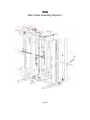
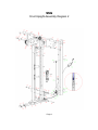
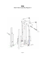
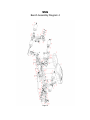
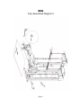
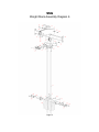
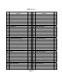
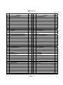
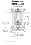
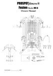
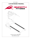
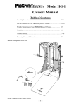
PROSPOTfitness
®
Fusion
SSG
“Space Saving Gym”
Featuring Prospot Fitness® Touch Sensor Technology
Owner’s Manual
Table of Contents
Assembly instructions
Diagrams
User Instructions
Maintenance
Trouble shooting
Parts list
Contact information
………………..pages 2-6
………………..pages 7-12
………………..pages 13-16
………………….page 17
………………….pages 18-19
………………….pages 20-21
………………….page 22
To Get Started:
Before assembly, choose a safe location for your
Prospot Fitness® SSG.
•
The SSG has a footprint of approximately 6’x 6’. The barbell is approximately 7’ long. Locate
your SSG away from any source of water. Do not allow any liquid to be near the machine or
spilled on any electrical part. Do not insert any object into the electrical box.
•
Approximate assembly time is 1-1/2 – 2 hours.
•
A flat area of 9’ x 9’ will be required to assemble and properly use the SSG.
•
You will need the following tools and a helper to complete the assembly:
•
•
•
•
•
•
•
17 mm, 19mm Hex Head Wrench or Adjustable wrench.
Metric Ratchet set
4 mm Allen Wrench
5 mm Allen Wrench
Philips Screw Driver
Scissors
Razor knife
•
Floor Padding, such as cardboard, to avoid scratching your floor during assembly.
•
HAND TIGHTEN all bolts. DO NOT fully tighten bolts until instructed to do so.
•
Assistance by a second person is recommended for some steps of this assembly.
•
The SSG uses several different lengths of bolts. Be careful to use the correct length of bolt
called for at each step of assembly. Bolt packs are label with part # and descriptions.
ALWAYS REMEMBER: After the initial set up of the system or after
performing any service on the unit, RESET the Computer on your ProSpot system
before using it. Just unplug the power supply from the Electronic Box, wait 30
seconds and plug back in. Resetting the Computer allows it to recalibrate and work
to its greatest efficiency.
Page 2
Assembly Instructions for the SSG
Step #1 MAIN FRAME ASSEMBLY
1. Place the (#17, #151) Base Rails opposite each other in the center of the assembly area as
shown in the illustration #1. Place (#53) Bottom Cross Brace between the two Base Rails so
that the side, pre-drilled holes of the Base Rails align with the holes of the Lower Frame
Cross Brace. Feed (#55) & (162) Wire Harness’s thru left & right base rails (#17 & #151) up
thru square cut out in rail. Place (#52) Upright support plates on each of rails, lining up the
predrilled holes and secure with the lower four (#107) bolts, (#90) flat washers and (#91)
lock nuts.
2. Now place (#31right, #35 left) Locking Posts on top of Base Rails (#17, #151) and secure
with four (#107) bolts, (#90) flat washers and (#91) lock nuts. Be careful of wires do not
pinch between metal pieces. This may take two people to perform this task.
3. Next connect the (#55) Base Frame Wire Harness to the (#136) Locking post wire Harness.
4. Now place the (#24 & #26) Inside & Outside Connecting Plates at top of (#31, #35 ) Locking
Posts and slide four (#107) bolts, (#90) flat washers to hold Plates in position. Make sure
(#41, #57) Barbell Cables that have the (#58) Weight Bar Cable Knuckles are on the side of
the bolt closest to the front of the unit.
5. Now position (#12) Top Rail on to these bolts and secure with(#90) flat washers and
(#91)lock nuts. This may take two people to perform this task.
6. Now install (#27) Large Double Groove Pulley between (#24 & #26) Inside & Outside
Connecting Plates according to diagram #2. When installing make sure (#58) Weight Bar
Cable Knuckles connected to (#41, #57) Barbell Cables are placed over this pulley
according to diagram #3. Make sure cables are not twisted.
7. Now install (#30) Small Double Groove Pulley between (#24 & #26) Inside & Outside
Connecting Plates according to diagram #2. When installing make sure (#18, #54) Lower
Cable Knuckles connected to (#41, #57) Barbell Cables are placed over this pulley
according to diagram #3. Make sure cables are not twisted.
8. Now bolt (#18,#54) Lower Cable Knuckles connected to (#41,#57) Barbell Cables to (#17,
#151) Base Rails using (#99) Bolt, (#100) Spacers, (#90 Flat Washers and (#91) Lock nuts.
Make sure cables are not twisted. Note: (#18, #54) Lower Cable Knuckles should be facing
(#31 right, #35 left) front toward Locking Posts.
9. Next connect (#136) Locking post wire Harness plug into (#18, #54) Lower Cable Knuckles.
10. Now place and install according to diagram #2, (#28, #58) left & right Selector Plates and
secure with four (#107) bolts, (#90) flat washers and (#91) lock nuts. Note: Openings in
Selector Plates should face downward.
STEP #2 – FRONT UPRIGHT INSTALATION
1. Now install (#15, #51) right & left Folding Uprights into (#28, #58) left & right Selector Plates
and onto stud on (#17,#151) Base Rails. Make sure brass bushings on stud are on top of
Upright’s bottom plate. Secure Base Rail stud with (#90) flat washers and (#91) lock nuts.
Now bolt upper pivot points at bottom of (#28, #58) left & right Selector Plates with (#104)
bolts & (#90) flat washers.
Page 3
STEP #2 – FRONT UPRIGHT INSTALATION (con’t)
2. Now feed (#58) Weight Bar Cable Knuckles connected to (#41, #57) Barbell Cables over
Double Groove Pulleys towards front of unit.
3. Now install (#141) Glide Roller Assembly with (#112) bolts and (#110) washers.
4. Now install (#105) Front Cable Keeper bolts with nylon sleeve with (#101) nuts, (#102)
washers. Make sure cables are not twisted.
5. Now install (#114) Rear Cable Keeper bolts with nylon sleeve with (#110) nuts, (#111)
washers. Make sure cables are not twisted.
6. Now install (#19, #32) right & left Weight Horns with (#99) bolts, (#90) flat washers and (#91)
lock nuts. Also install (#20) V-shaped Rubber Bumper Rings on Weight horns.
STEP #3 – WEIGHT STACK INSTALLATION & SENSOR WEIGHT BAR
1. Now place (#71) Bottom frame assembly onto (#53) Bottom Cross Brace according to
diagram 6.
2. Find (#143) Electronic Box Locating Board and remove (#134) Cover. Now slide two (#92)
bolts & (90) flat washers thru the two holes. Now place the (#134) Cover & (#144) Electronic
box behind (#53) Back Base Rail. Pull (#55) Base Rail Wire Harness through the (#134)
Cover’s side holes and plug into (#145) Electronic Box connectors. Make sure LED lights
line up with opening on Cover and 12V power receptacle is facing out. Now attach (134)
Cover to (#143) Locating Board with small screws provided.
3. Now slide the two bolts from the (#143) Electronic Box Locating Board thru holes and secure
with (#90) flat washers and (#91) lock nuts.
4. Remove (#1, #2, #140) Weight Stack Plates and Top Plate from their cartons and place near
the unit for installation0.
5. Insert (#6) Weight Stack Guide Rods into (#10) Guide Rod Cup Holders.
6. Add weight plates. This step is easier to perform with assistance from another person. Tilt
(#6) Weight Stack Guide Rods to the side so that the weight plates can be slid onto them.
Starting with the bottom #100 weight plate slide down on Guide Rods. Keep weight plates in
order and make sure the weight indicator numbers face inward. Repeat until all weight
plates are installed. Then install top plate with (#8) Selector Key on cord facing toward the
inside of the unit.
7. Slide (#9) Top Guide Rod Plate onto the (#6) Guide Rods and position under (#12) Top
Rail’s predrilled holes and insert (#89) bolt and (#90) flat washers. Now position (#42) Lat
Boom over these bolts and secure with (90) flat washers and (#91) lock nuts.
8. According to diagram #3, now connect (#47) Lat Cable to (#140) Top Plate threaded hole.
Thread in approximately 1/2". This can be adjusted later.
9. Now according to diagram #3, connect (#137) Low Row Cable or with (#45) Cable clip to
loop on (#71) Bottom frame assembly.
10. Now install (#3) Weight Horns to the (#1) 20 lb plate that has the threaded holes, using (#86)
bolts, (#87) flat washers and (#118) lock washers. Also add (#4) rubber disc.
Page 4
STEP #3 – WEIGHT STACK INSTALLATION & SENSOR WEIGHT (con’t)
11. Now install (#34) Accessory holders using (#99) bolts, (#90) flat washers & (#91) lock nuts.
12. Now tighten all bolts just installed. First tighten the bolts and nuts holding the (#15, #51) right
& left Folding Uprights hinge points. Then start tightening bolts starting at the floor and work
your way up the unit until all bolts are tight. Do not over tighten. Check folding function of
unit. Adjust by loosing bolts and move frame member and retighten.
13. Next install (#7) Logo plate with (#97) screws.
14. Now install (#23 & #43) Locking Post Covers onto (#31right, #35 left) Locking Posts using
(#115) screw and (#101) washer. Tighten screws.
15. Now connect (#145) 12V Power supply to Electronic Box. A flashing green light should
appear to verify power and ready.
16. Now its time to install (#46) Sensor Weight Bar. Using a 5mm allen wrench remove the
(#139) Socket Button Head Screw & (#59) End Cap off each end. Now using a 4mm allen
wrench, remove the (#38) Spacer collar from each end of Sensor Weight Bar. This may
take two people to perform this next task. Place Sensor Weight Bar in front of unit. Grab and
touch the metal plate on the (#58) Weight Bar Cable Knuckles that are on the front of the
unit. This will trigger the sensor to release the Cables to allow down ward movement. Pull
down to waist level and hold these at this position. Make sure Cables are not twisted and the
metal face of Cable Knuckle is facing inward. If you let go the Cables, they will retract back
into unit. Now have your assistant slide end of the (#46) Sensor Weight Bar thru holes in
knuckles on each side. Note: There is a key slot cut out in Cable Knuckle for a metal pin on
Sensor Weight Bar to slide thru. You can now let go of Sensor weight Bar. It will not move
unless Sensor is triggered. Now reinstall (#38) Spacer collar so that it is against Cable
Knuckle and tighten with 4mm allen wrench. Now install the (#37) Olympic adapters, (#59)
End Cap and tighten (#139) Socket Button Head Screw with 5mm allen wrench.
STEP #4 – BENCH ASSEMBLY
1. Now according diagram #4, install (#79) spring shocks to previously installed (#71) Bottom
frame assembly using (#125) bolt, (#130) Spacer, (#101) washer, (#102) nut and tighten.
11. Now position (#152) Bench Slider Rail between (#82 & #83) Bench Swivel Plates and secure
with (#107) bolts, (#90) flat washers and (#91) lock nuts. Tighten Securely.
2. Now lift Bench Assembly up to vertical position and hold. Do not let go. This may take two
people to perform this task. Now connect (#78) Spring Shock Mounting Bracket to bottom of
(#152) Bench Slider Rail using (#115) Screws and (#101) washers. Tighten securely.
3. Now lower Bench Assembly to floor. Now install (#69) Bench Seat Frame using (#124) bolt,
(#90) flat washer and (#91) lock nut and tighten securely.
4. Now install (#122) Seat Adjustment Frame into (#69) Bench Seat Frame slot and secure
with bolt (#124) bolt, (#90) flat washer and (#91) lock nut and tighten securely.
5. Next according to diagram #4, install (#66) Bench Seat Pad onto 69) Bench Seat Frame with
(#138) bolt and (#87) washer and tighten securely.
6. Now according to diagram #4, install (#129) Plastic Spacing Sleeve & (#62) Foam Roller
onto (#69) Bench Seat Frame tubes.
Page 5
STEP #5 – SSG ACCESSORIES & MISC.
1. Now according to diagram #4, install (#129) Plastic Spacing Sleeve & (#62) Foam Roller
onto (#85) Lat Leg Hold Down tubes. At this time place accessory into position on Bench
and lock with (#84) Locking Pin. If (#84) Locking Pin does not slide through easily, loosen
bolts on (#82 & #83) Bench Swivel Plates, slide pin through and then tighten securely. Now
remove Lat Leg Hold Down and store in one of the (#34) Accessory holders according to
diagram.
2. Now according to diagram #1, #2 & #3 prepare to install (#23) & (#43) Locking Post Covers.
First connect Neon light wire harness into ( #162) & (163) Wire Harness’s. Next using (115)
Screws and (#101 washers) attach (#23) & (#43) Locking Post Covers on their proper sides
according to diagram #1, #2 & #3.
3. Add (#45) Clip to (#48) Low Row Bar and attach (#49) Chain. Now place in holder located
on left Locking Post Cover.
4. Place (#44) Lat Bar in holder located on right Locking Post Cover.
5. Add (#45) Clip to (#47) Lat Cable.
6. Add (#45) Clip to (#137) Low Row Cable and connect (#133) Bench Cable.
7. Now according to the diagram #4, install (#129) Plastic Spacing Sleeves & (#62) Foam
Rollers onto (#63) Roller Support Tube of Leg Developer. Now store in one of the (#34)
Accessory holders according to diagram.
8. Now test folding function of unit for proper clearance of stored accessories in holders. If they
interfere, try reversing front to back.
STEP #6 – WALL BRACKET INSTALATION
DO NOT OMIT THIS STEP OF THE INSTALLATION –IMPORTANT TO
SAFETY OF THE USER. TIPPING IS POSSIBLE IF NOT SECURED
PROPERLY.
1. Place unit against wall in desired position. Find nearest wall stud at rear of (#42) Lat Boom.
Place (#13) Wall bracket left or right side of Lat Boom so that of the small predrilled holes line up
with the stud in wall. Now mount (#13) Wall Bracket to the closest bolt hole on bracket using the
rear pulley bolt of the (#42) Lat Boom and tighten securely. See diagram #1. Now fasten the
Wall Bracket to the wall using screw (#102) #12 x 1-1/2” into stud. Test for strength.
Page 6
SSG
Main Frame Assembly Diagram 1
Page 7
SSG
Front Upright Assembly Diagram 2
Page 8
SSG
Rear Frame Assembly Diagram 3
Page 9
SSG
Bench Assembly Diagram 4
Page 10
SSG
Fully Assembled Diagram 5
Page 11
SSG
Weight Stack Assembly Diagram 6
Page 12
!!Read!!
This Page Before Using Your SSG
1.
CAUTION:
This machine involves the risk of possible injury by its user.
2.
THE FOLLOWING RULES SHOULD BE CARFULLY
FOLLOWED:
• Consult a physician or other healthcare provider before
beginning an exercise program.
• If you are in bad health or are handicapped, ask for the
opinion of your physician and exercise only under qualified
supervision.
• Discontinue exercising if you experience any lightheadedness, dizziness or shortness of breath and consult
your physician.
3.
Keep small children and others at a safe distance from all moving
parts. The up and down movement of the weights can be
dangerous.
Never allow your fingers, toes, hair, other body parts or loose
clothing to come near weights while they are in motion.
Never attempt to exercise with more weight than you are
physically able to handle.
Prior to every use, inspect your machine to ensure all parts are
free from defect and are fully operational.
Check all fasteners to make sure none have loosened with use.
Tighten any loose fasteners if necessary.
•
•
•
•
4.
Warning: Never perform any maintenance on the unit while the
power supply is plugged into the wall.
Page 13
User Instructions for the Prospot Fitness® SSG
Do not allow any liquid to be near the machine or spilled on any electrical part. Do not insert any
foreign object into the electrical box or attempt to open it. This unit is designed for climate
controlled environments (indoor use).
Connect the power supply to a standard 110-volt household current. While connecting the power
supply do not touch the barbell as this may interfere with the computer’s initial settings. If you
need to reset the computer, simply unplug the power supply, wait 10 seconds and reconnect it. It
is recommended that surge protection be used to help protect and extend the life of the
Electronic Box of the unit from power surges and lightening strikes. A flashing green light will
appear on the Electronic Box when power is on. When sensors are activated, a steady red light
will also come on.
Note: Detailed, visual instructions can be found on the included instructional DVD.
Space Saver Feature
To fold up the SSG:
1. Move Bench to farthest position from back of unit and lower to flat position.
2. Place accessories in their respective holders and put weight plates on the storage posts.
3. Grasp bench handle and raise the bench to its full, upright position. Secure in position
with locking knob.
4. Position the barbell and place diagonally across the front of the unit, ensuring that the
Weight Bar does not exceed the width of main frame.
5. Release the locking knob located at the top of each Front Folding Uprights (side frames)
and fold in and lock into hole on selector plate. Never perform exercises while sides are
folded.
To unfold:
1. Release locking knob from each Front Folding Uprights (side frames) and extend
outward, locking each in place with the locking knob.
2. Raise barbell to uppermost position.
3. Remove locking pin from upright bench, grasp bench handle and lower it to the floor,
ensuring that the front support leg is fully extended and stable.
Touch Sensor Barbell Operation
1. Rotate the barbell so that the Touch Sensor Strip embedded in the barbell is touching
your fingertips. It is necessary for your fingertips to maintain skin contact with the Touch
Sensor Strip throughout your free-weight exercise.
2. Grasp the barbell using what is called a ‘false’ grip in which the thumb does not wrap
around the bar but rests alongside the index fingers. Using this type of grip will prevent
your thumb from maintaining skin contact with the Touch Sensor Strip when you attempt
to lock the bar in place.
3. Once you have grasped the barbell, you will hear a soft ‘click’ and a solid red light will
appear on the Electronic Box in addition to the flashing green power light.
4.
While still grasping the barbell, lift about 1”, using an even upward lifting motion on both
sides of the barbell. This upward movement will disengage the locking mechanism. If
you have performed this step correctly, the barbell will now be under your control.
5. Always remember to secure all weight plates with supplied spring clips. You are now
ready to begin your free-weight exercise routine.
Page 14
6. Always maintain control of the movement of the barbell. Do not allow the barbell to
swing against the machine frame, as this may cause damage to the finish. Do not
attempt to throw or slam the barbell attached to the cables, as this may result in damage
to the locking mechanism. Intentional misuse of the SSG will void any and all
warranties.
Spot Block Plates and Barbell Loading
Always use Spot Block Plates when using barbell as a secondary locking backup. The Spot
Block Plates can also be used as a training aid by limiting barbell movement when
exercising. To position the Spot Block Plates:
1. Place the barbell into the lowest position for the exercise you will be performing. To
move the Spot Blocks Plates, remove by grabbing handles and lifting up. You will see
the top hook and stop pin that goes in the holes. Place the Spot Blocks Plates above
exposed tip of locking pin on rear support posts. This will now restrict the movement of
Sensor Weight Bar beyond this point.
2. Make certain the barbell is level before loading weight plates. Level the barbell by
raising up one end of the barbell until it is level. Load weights evenly on both sides of
the barbell.
Note: The SSG has a 500-pound capacity. Do not exceed capacity!
Bench Operation
•
•
•
The back seat pad adjusts from flat to incline position. To adjust, raise pad and allow
the pad lever to lock in place.
The seat pad has two positions flat and incline. Use the handle to adjust the pad
between these two positions.
The entire bench slides forward and back along its frame to four separate positions.
The position of the bench is determined by the exercise being performed (refer to
instructional DVD). Turn the slider knob counter clockwise to loosen then pull the knob
to release the bench. Move seat into desired position then release knob and turn it
clockwise to tighten.
Using the Leg Developer
The leg developer is used to perform the leg extension and leg curl exercises.
Leg Extension:
1. Retrieve the leg developer and turn it so that the locking pin and foam rollers face
forward, away from the bench.
2. Slide the square, hollow tube onto the bench frame and secure with the locking pin.
3. Extend leg extension curl arm to its lowest position by pulling out the locking knob. (The
leg extension curl arm is located directly beneath the foot rollers of the leg developer.)
Once positioned, lock in place by tightening the locking knob.
4. Insert the bench cable into the slot on the front of the leg extension arm using the robber
ball stopper.
5. Raise bench back and seat pads, then adjust shin support pads to comfortable position.
6. Select desired amount of weight on the weight stack.
Page 15
Leg Curl:
1. Retrieve the leg developer and turn it so that the locking pin and foam rollers face
forward, away from the bench.
2. Slide the square, hollow tube onto the bench frame and secure with the locking pin.
3. Insert the bench cable into the slot on the front of the leg extension arm using the flat,
metal stopper. (Leg extension curl arm should be in its uppermost, or home, position.)
4. Bench back pad and seat should be in the lowest positions. Adjust ankle rollers to a
comfortable position.
5. Select desired amount of weight on the weight stack.
Cable Pulley Operation
The SSG is equipped with a high/low cable pulley. The high pulley can be used with the bench
in the upright or lowered position. The lower cable pulley is accessible when the bench is raised
and locked. When using the lower cable pulley, the barbell can be stowed on top of the unit to
keep it out of the way. Insert the weight-selector pin into the weight stack to add resistance to
the cable pulley.
To use the Leg Hold Down during lat exercises:
1. Place the Leg Hold Down onto Bench Rail and lock down with pin.
2. Adjust the leg rollers to fit against your lap.
The frame sides have three positions: inward, straight out and hyper-extended. To use the side
lat bar, some users may find it more comfortable to move the frame sides outward to the hyperextended position. Be sure to lock in place with the locking knob.
Page 16
Maintenance Program for the SSG
The SSG is made of durable materials and has been factory tested to assure proper function
and reliability. It is designed in a way to allow easy replacement of parts both mechanical and
electrical if the need should ever arise. If you are a new owner of a SSG system, three
important things need to be done to assure prompt service under the warranty:
1. Fill out and fax or mail to us your Product Warranty Registration Card along
with a copy of your sales receipt (proof of purchase).
2. Your system needs to be set up properly according to the assembly manual.
3. Follow user instructions on how to properly use the system.
Note:
The SSG is recommended for climate-controlled environments. Outdoor use is
not recommended and will void the warranty.
Carefully inspect machine before each use to determine that it is free from
defects.
Do NOT use the machine if you find:
1. A loose, broken or frayed power cord – (needs to be replaced)
2. Any broken, cracked, torn, frayed or defective part of the machine – (needs to
be replaced)
3. Loose bolts or fasteners. Check all fasteners to make sure none have loosened
with use. Tighten any loose fasteners.
4. Pulleys sticking or Cables binding. Check for free movement of all cable
and pulleys. Adjust or replace if necessary.
Lubrication:
Lubricate the Internal Locking Blocks periodically by spraying a standard silicone lubricant
(found in hardware stores) into the top of the # 4 & 5 Locking Upright Posts in the inside corners
of the tube. Do not over lubricate.
Page 17
Trouble-Shooting
How the Patented ProSpot System works:
Starting from the Computer Brain, a signal is sent from the left & right side, thru the L & R Grey
Base Frame Wire Harness (white lead), Locking Post wire harness to the Lower rear Cable
Knuckle connector, to inside Barbell Cable to the Sensor on the Barbell. When skin contacts is
made with Barbell Sensors, the signals return to the Computer Brain, at which a 12-volt charge
is sent via the Base Frame Wire Harness to the contact strips in the Locking Post to the
solenoids, to release the spring loaded Slider Block Locking Pins when the Barbell is lifted,
allowing the Barbell to move up and down. When skin contact with Barbell Sensor is broken by
either hand, the Computer Brain reads this and stops the 12-volt charge to the solenoids, at
which time, the spring loaded Locking Pins instantaneously engages the hole on the Guide Post
and locks the Barbell from any downward movement.
Trouble Shooting of ProSpot Systems
ALWAYS REMEMBER: After performing any service on the unit, RESET the Computer on your
ProSpot system before using it. Just unplug the power supply Electronic Box, wait 30 seconds
and plug back in. Resetting the Computer allows it to recalibrate and work to its greatest
efficiency.
Electrical Service Inspection Checklist:
1. Check for proper functioning of wall receptacle. (Test plug for power)
a. If bad, find new AC power supply.
2. Check wall transformer connection to Electronic Box. Should not be bent or loose.
a. If bad, replace Electronic Box.
3. Check for green flashing light, the indication power to Electronic Box.
a. If no green light, test 12V Wall Adapter for 12-17 volts output. If voltage is less
or none, replace 12Vpower supply.
4. Inspect white connectors from Base Frame Wire Harness connection on Electronic Box
for loose wires.
a. If loose, plug in tight.
b. If broken, replace Base Frame Wire Harness.
5. Inspect Base Frame Wire Harness for possible pinching in frame during assembly.
a. Replace Base Frame Wire Harness if damaged or defective.
6. Inspect Base Frame Wire Harness connection to Locking Post Wire harness.
a. If loose, plug in tight.
b. If broken, replace Base Frame Wire Harness or Locking Post Wire Harness.
7. Inspect Locking Post Wire Harness connection to Contact Strips.
a. If loose, plug in tight.
b. If broken, replace Locking Post Wire Harness.
c. Inspect Locking Post Wire Harness plug in connector to Lower Cable Knuckle.
d. If loose, plug in tight.
e. If broken, replace Locking Post Wire harness.
8. Check contact points of Sensor Weight Bar.
a. If no contact, adjust Sensor Collar closer. So that sensor Collar pin makes better
contact with metal plate on Cable Knuckle.
Page 18
Trouble-Shooting (con’t)
Symptom:
Solution:
Sensor Weight Bar will not unlock.
1. Remove covers on both sides to gain access to Locking Post Wire
Harness.
2. Unplug Brown Sensor plugs and hold one in each hand at the same time.
3. If sensor triggers (red light on box) then, Wire Harness is good.
a. Now check connections on Weight Bar / Cable-Knuckle Assembly.
Make adjustments.
4. If sensor fails to trigger (no red light) then:
a. Re-check both Wire Harness’s with Meter (Continuity test) for
defective wire and replace.
Symptom:
Solution:
Sensor Weight Bar locks prematurely during work out.
1. Perform Adjustments on Weight Bar / Cable-Knuckle
assembly.
2. Check Wire Harness for defective wire. (Continuity test)
Symptom:
Solution:
One side of system will not unlock.
1. Check Double Cable Pulleys for free movement.
2. Check connections from Locking Post Wire Harness to contact strips.
3. Check free movement of Locking Pin. (Manually pull down Pin)
4. Trigger Sensor and test for 10-12 volts at Solenoid connection.
a. If 10-12 volts the replace Solenoid.
b. If no voltage, then check Wire Harness for defective wire.
(Continuity test)
c. If Wire Harness is good the replace Electronic Box.
Symptom:
Solution:
Sensor Rod on Weight bar keeps popping up.
1. Remove Sensor Collar and Sensor Rod.
2. Straighten any bends. (If too bent up, replace.)
3. Before reinstalling, bend angle in Sensor Rod slightly downward, so that
there is tension on Sensor Rod to seat it.
Page 19
SSG Parts List
Part
#
1
2
3
4
5
6
7
8
9
10
11
12
13
14
15
16
17
18
19
20
21
22
23
24
25
26
27
28
29
30
31
32
33
34
35
36
37
38
39
40
41
42
Description
Weight Stack Weight Plate 2nd plate
Weight Stack Top Plate
Weight Stack Plate Horns
Rubber Disc 72 dia 45mm
Weight Stack Selector Pin
Weight Stack Guide Rod
Logo Plate
Rubber Cap
Guide Rod Top Plate
Guide Rod Cup
Large Single Groove Pulley
Top Rail
Wall Bracket
End Cap
Right Front Folding Upright
Foot End Cap 75x45mm
Right Base Rail
Right Rear Cable Knuckle
Right Side Weight Plate Holder
V-Shape Rubber Bumper Ring
Right Locking Block Assembly
Locking Block Slider Sleeve
Right Locking Post Cover
Outside Connecting Plate
Adjusting Locking Pin
Inside Connecting Plate
Large Double Groove Pulley
Right Folding Selector Plate
Wheel
Small Single Groove Pulley
Right Locking Post
Left Side Weight Plate Holder
Insert Plastic Cap
Accessory Holder
Left Locking Post
Spring Clip 50mm dia
Olympic Adapter
Plastic Locking Sleeve
Sensor Collar
Spot Block Plate
Inside Weight Bar Cable
Lat Boom
QTY
1
1
2
2
1
2
1
2
1
4
7
1
1
2
1
4
1
1
3
6
1
4
1
2
3
2
4
1
2
9
1
3
2
2
1
2
2
2
2
2
1
1
Part
#
43
44
45
46
47
48
49
50
51
52
53
54
55
56
57
58
59
60
61
62
63
64
65
66
67
68
69
70
71
72
73
74
75
76
77
78
79
80
81
82
83
84
Page 20
Description
Left Locking Post Cover
Lat Bar
Cable Clip
Sensor Weight Bar
Lat Cable
Low Row Bar
Chain
Left Folding Selector Plate
Left Front Folding Upright
Upright Support Plate
Bottom Cross Brace
Left Rear Cable Knuckle
Cross Brace Wire Harness
Rubber Bumper Ring 50/80mm
Outside Weight Bar Cable
Weight Bar Cable Knuckle
Olympic Adapter Retaining Plug
Left Locking Block Assembly
Weight Stack selector pin
Foam Roller
Roller Support Tube
Screw Down Pull Pin
Lat Leg Hold Down Inner Tube
Bench Seat Pad
Bench Back Pad
Leg Developer Assembly
Seat Frame
End Cap
Bottom Frame Assembly
Roller Retaining Cap
End Cap
Bench Support Leg
Tethered Locking Pin
Bench Back Pad Support Rail
Bench Angle Adjusting Support
Spring Shock Mounting Bracket
Spring Shock
Bench Slider Insert
Bench Slider
Right Bench Swivel Plate
Left Bench Swivel Plate
Lat Leg Hold Down Locking Pin
QTY
1
1
4
1
1
1
1
1
1
2
1
1
2
2
1
2
2
1
1
6
2
3
1
1
1
1
1
3
1
6
1
1
1
1
1
1
2
2
1
1
1
1
SSG Parts List
Part
#
85
86
87
88
89
90
91
92
93
94
95
96
Description
Lat Leg Hold Down Tube
Hex Head Bolt M8*20
Flat Washer M8
Socket Head Cap ScrewM10*45(full thread)
Hex Head Bolt M12*70
Flat Washer M12
Hex Nut M12
Hex Head Bolt M12*105
Hex Head Bolt M10*40
Flat Washer M10
Hex Nut M10
Hex Head Bolt M10*45
QTY
1
8
13
1
2
94
48
4
6
33
15
1
Part
#
127
128
129
130
131
132
133
134
135
136
137
138
Cross Head countersink screw M3*6
Socket Button Head Cap Screw M8*40
Hex Head Bolt M12*95
Spacer
Flat Washer M6
#12 x 1-1/2" RH Wood Screw
Socket Button Head Cap Screw M10*50
Hex Head Bolt M12*15
Hex Head Bolt M6*65
Hex Head Bolt M10*70
Hex Head Bolt M12*100
Hex Head Bolt M10*100
Pulley Spacer
Flat Washer M5
2
4
18
4
20
1
2
2
2
2
18
4
4
24
139
140
141
142
143
144
145
146
147
148
149
150
151
152
Description
Hex Head Bolt M12*65
Leg Developer Top Bracket
Plastic Spacing Sleeve
Spacer Sleeve
Small single groove Pulley
Hex Nut M8
Bench Cable
Electronic Box Cover
Double Pulley Assembly
Locking Post Wire Harness
Low Row Cable
Hex Head Bolt M8*40
Socket Button Head Screw M8*40(full
thread)
Weight Stack Weight Plate
Guide Roller frame bracket
Guide Rollers
Locating Board
Electronic Box
12v Power Supply
Round Inner Plug 45mm
Spring Clamp Holder
Row Bar Bottom Holder
Sheet metal screw
Lat Bar bottom holder
Left Base Rail
Bench Slider Rail
97
98
99
100
101
102
103
104
105
106
107
108
109
110
111
Hex Nut M5
14
153
Exercise Ball
112
113
114
115
116
117
118
119
120
121
122
123
124
125
126
Hex Head Bolt M5*10
Hex Head Bolt M5*45
Hex Head Bolt with Sleeve M5*90
Pan Cross Head M6*10
Socket Button Head Cap Screw M12*15
Socket Head Round Screw M5*20
Spring Washer M8
Socket Button Head Screw M10*15
Sleeve Nut
Sleeve Nut
Seat adjustment frame
Hex Head Bolt M10*110
Hex Head Bolt M12*110
Hex Head Bolt M6*30
Sleeve
8
4
4
12
2
8
4
4
1
1
1
1
3
2
1
154
155
156
157
158
159
160
161
162
163
164
165
166
167
168
Work Out Mat
Light Switch
Hex Nut M3
Flat Washer M3
Pan Cross Head M3*15
Neon Light
Power Cord
Neon Light Power Supply
Neon Light Wire Harness
Neon Light switch Wire Harness
Hex Nut
Washer
Pan Cross Head
Air Pump
Page 21
QTY
1
1
6
2
1
3
1
1
1
2
1
6
2
8
2
4
1
1
1
8
2
1
8
1
1
1
1
1
1
4
4
4
2
1
1
1
1
2
2
2
1
Warranty & Contact Information
Each PROSPOT Fitness® Product comes with a limited parts replacement
warranty. Please refer to the actual warranty card included with your system for
specific coverage.
Remember: To activate your Warranty, fill out and fax or mail to us your Product
Warranty Registration Card along with a copy of your sales receipt (proof of
purchase) if your dealer has not done this at time of purchase.
If you have any questions about performance under this limited warranty, please
write us at:
PROSPOT Fitness, Inc.
Attn: Warranty Service
2000 Newpoint Pl Pkwy Ste. 500
Lawrenceville, GA 30043
Office (770) 446-9299
Fax (770)-446-7213
If your ProSpot Fitness® system needs service, please
contact first your local Prospot authorized Dealer where you
purchased the unit.
You are always welcome to Contact ProSpot Fitness® Technical Support:
Our Service Department can be reached M-F 9-5 pm EST.
Or e-mail us: [email protected]
If ordering replacement parts, please refer to the Owners Manual for part
numbers and description.
Note: Owners Manuals & Warranty Registration cards can be down loaded from
our web site.
For more information please refer to our Website at: www.prospotfitness.com
Page 22