1
SITRANS F
Coriolis Flowmeters
SITRANS FC430 with HART
Service Manual
Edition
12/2013
Answers for industry.
SITRANS F
Coriolis flowmeters
SITRANS FC430 with HART
Service Manual
This Service Manual applies to Siemens products
SITRANS FC430 with order codes commencing
7ME4613, 7ME4603, 7ME4623, and 7ME4713
12/2013
A5E03736884-02
Introduction
1
Description
2
Troubleshooting
3
Alarms and system
messages
4
Service and maintenance
5
Legal information
Warning notice system
This manual contains notices you have to observe in order to ensure your personal safety, as well as to prevent
damage to property. The notices referring to your personal safety are highlighted in the manual by a safety alert
symbol, notices referring only to property damage have no safety alert symbol. These notices shown below are
graded according to the degree of danger.
DANGER
indicates that death or severe personal injury will result if proper precautions are not taken.
WARNING
indicates that death or severe personal injury may result if proper precautions are not taken.
CAUTION
indicates that minor personal injury can result if proper precautions are not taken.
NOTICE
indicates that property damage can result if proper precautions are not taken.
If more than one degree of danger is present, the warning notice representing the highest degree of danger will
be used. A notice warning of injury to persons with a safety alert symbol may also include a warning relating to
property damage.
Qualified Personnel
The product/system described in this documentation may be operated only by personnel qualified for the specific
task in accordance with the relevant documentation, in particular its warning notices and safety instructions.
Qualified personnel are those who, based on their training and experience, are capable of identifying risks and
avoiding potential hazards when working with these products/systems.
Proper use of Siemens products
Note the following:
WARNING
Siemens products may only be used for the applications described in the catalog and in the relevant technical
documentation. If products and components from other manufacturers are used, these must be recommended
or approved by Siemens. Proper transport, storage, installation, assembly, commissioning, operation and
maintenance are required to ensure that the products operate safely and without any problems. The permissible
ambient conditions must be complied with. The information in the relevant documentation must be observed.
Trademarks
All names identified by ® are registered trademarks of Siemens AG. The remaining trademarks in this publication
may be trademarks whose use by third parties for their own purposes could violate the rights of the owner.
Disclaimer of Liability
We have reviewed the contents of this publication to ensure consistency with the hardware and software
described. Since variance cannot be precluded entirely, we cannot guarantee full consistency. However, the
information in this publication is reviewed regularly and any necessary corrections are included in subsequent
editions.
Siemens AG
Industry Sector
Postfach 48 48
90026 NÜRNBERG
GERMANY
Order number: A5E03736884
Ⓟ 12/2013 Technical data subject to change
Copyright © Siemens AG 2012 - 2013.
All rights reserved
Table of contents
1
2
3
4
5
Introduction ............................................................................................................................................. 5
1.1
Purpose of this documentation ......................................................................................................5
1.2
History ............................................................................................................................................5
1.3
Safety instructions ..........................................................................................................................6
1.4
Notes on warranty ..........................................................................................................................6
1.5
Product information ........................................................................................................................6
1.6
Laws and directives .......................................................................................................................6
Description .............................................................................................................................................. 7
2.1
Design ............................................................................................................................................7
2.2
SensorFlash concept ...................................................................................................................11
2.3
Firmware update ..........................................................................................................................13
Troubleshooting .................................................................................................................................... 15
3.1
Troubleshooting overview ............................................................................................................16
3.2
Clear alarms and system messages (A1) ....................................................................................17
3.3
3.3.1
3.3.2
Prove correct sizing and calculate measurement error (A2) .......................................................17
Prove correct sizing .....................................................................................................................18
Calculate measurement error ......................................................................................................19
3.4
Inspect the application (A3) .........................................................................................................20
3.5
3.5.1
3.5.2
Check sensor specific data (A4) ..................................................................................................22
Verify sensor diagnostic parameters ...........................................................................................22
Measure resistance on sensor connector ....................................................................................25
3.6
Improve the application (A5) ........................................................................................................26
Alarms and system messages ............................................................................................................... 29
4.1
Overview of messages and symbols ...........................................................................................29
4.2
Alarm messages ..........................................................................................................................30
Service and maintenance ...................................................................................................................... 41
5.1
Diagnostics tools ..........................................................................................................................41
5.2
Maintenance work ........................................................................................................................41
5.3
Regular maintenance ...................................................................................................................43
5.4
5.4.1
5.4.2
Spare parts overview ...................................................................................................................43
Replaceable components ............................................................................................................45
Toolkit ...........................................................................................................................................49
5.5
Spare parts replacement with SensorFlash synchronization .......................................................49
SITRANS FC430 with HART
Service Manual, 12/2013, A5E03736884-02
3
Table of contents
5.5.1
5.5.2
5.5.2.1
5.5.2.2
5.5.2.3
5.5.2.4
5.5.2.5
5.5.3
5.5.3.1
5.5.3.2
5.5.3.3
5.5.3.4
Removing SensorFlash ............................................................................................................... 50
Replacement of transmitter/sensor spare parts .......................................................................... 51
Compatibility check mechanic spare parts .................................................................................. 51
Replacing sensor (remote version) ............................................................................................. 52
Replacing sensor (compact version) ........................................................................................... 54
Replacing transmitter (compact version) .................................................................................... 55
Replacing transmitter (remote version) ....................................................................................... 56
Replacement of electronic parts ................................................................................................. 58
Compatibility check electronic spare parts .................................................................................. 58
Replacing the DSL cassette ........................................................................................................ 60
Replacing the sensor interface cassette (compact version) ....................................................... 64
Replacing the transmitter cassette .............................................................................................. 67
5.6
5.6.1
5.6.2
5.6.3
Spare parts replacement without SensorFlash synchronization ................................................. 69
Replacing the sensor interface cassette (remote version) .......................................................... 69
Replacing the I/O cassette .......................................................................................................... 72
Replacing the power supply ........................................................................................................ 74
5.7
Upgrading the application from hardware revision 1 to 2 ........................................................... 76
5.8
Ordering ...................................................................................................................................... 76
Index .................................................................................................................................................... 79
SITRANS FC430 with HART
4
Service Manual, 12/2013, A5E03736884-02
1
1
Introduction
1.1
Purpose of this documentation
This Service manual contains all information that you will require to replace components and
to upgrade software and refresh SensorFlash.
For information about safe usage of the system, refer to the Operating Instructions and
safety related manuals all available on product CD and on the Internet at Technical support
(http://www.siemens.com/flowdocumentation)
Read this Service manual carefully before you start any service and maintenance work. In
order to use the device correctly, first make yourself acquainted with its principle of
operation.
The Service manual is targeted at service and maintenance technicians.
1.2
History
The following table shows major changes in the documentation compared to the previous
edition.
Edition
Remarks
05/2012
First edition
SW version
SIMATIC PDM driver 1.00.00
FW revision
Compact version:
–
System: 03.00.00
–
Transmitter: 02.00.09
–
LUI: 01.02.15
–
Sensor: 03.00.00
Remote version:
12/2013
General update
SensorFlash concept
added
Troubleshooting chapter
improved
SIMATIC PDM driver 2.00.00-**
–
System: 02.00.02
–
Transmitter: 02.00.09
–
LUI: 01.02.15
–
Sensor: 02.00.00
Compact version:
03.02.00-**
Remote version:
02.02.00-**
Spare part replacement
chapter improved
SITRANS FC430 with HART
Service Manual, 12/2013, A5E03736884-02
5
Introduction
1.3 Safety instructions
1.3
Safety instructions
Before carrying out any repair work, the instructions for safe handling of the device must be
read and understood. See the Operating Instructions.
1.4
Notes on warranty
The contents of this manual shall not become part of or modify any prior or existing
agreement, commitment or legal relationship. The sales contract contains all obligations on
the part of Siemens as well as the complete and solely applicable warranty conditions. Any
statements regarding device versions described in the manual do not create new warranties
or modify the existing warranty.
The content reflects the technical status at the time of publishing. Siemens reserves the right
to make technical changes in the course of further development.
1.5
Product information
The Service manual is available from the Intranet at the Siemens Industry Online Support
site http://support.automation.siemens.com/Flow.
SITRANS FC430 comes with a USB service port to enable easy service through SIMATIC
PDM software. The SIMATIC PDM driver is available for download from the Siemens
Industry Online Support site http://support.automation.siemens.com/flow
1.6
Laws and directives
Observe the test certification, provisions and laws applicable in your country during
connection, assembly and operation. These include, for example:
● National Electrical Code (NEC - NFPA 70) (USA)
● Canadian Electrical Code (CEC) (Canada)
Further provisions for hazardous area applications are for example:
● IEC 60079-14 (international)
● EN 60079-14 (EC)
SITRANS FC430 with HART
6
Service Manual, 12/2013, A5E03736884-02
2
2
Description
2.1
Design
Versions
The SITRANS FC430 flowmeter uses the Coriolis principle to measure flow and is available
in a remote and a compact version.
● Compact version: One single mechanical unit where the transmitter is directly mounted
on the sensor.
● Remote version: Transmitter and sensor installed separately. The remote system is
composed of SITRANS FCS400 sensor unit with a front end with Digital Sensor Link
(DSL) directly mounted on the sensor and remotely connected to a SITRANS FCT030
transmitter. The DSL performs the signal processing of all measured signals in the
sensor. The connection between transmitter and sensor is 4-wire providing power and
high-integrity digital communication between DSL and the transmitter.
Figure 2-1
Compact versions
Figure 2-2
Remote version with M12 connection
SITRANS FC430 with HART
Service Manual, 12/2013, A5E03736884-02
7
Description
2.1 Design
Figure 2-3
Remote version with terminated cable
Sensor design
All primary process measurement of mass and volume flow, density and process
temperature are made in the DSL.
The FCS400 sensor is provided with two parallel bent tubes welded directly to the process
connections at each end through a manifold. The FCS400 sensor is available in a non-safe
and an intrinsically safe (IS) design.
The sensors are available in AISI 304 stainless steel. The enclosure is made of AISI 316L
stainless steel and has a pressure rating of 20 bar (290 psi) for DN 15 to DN 50 and 17 bar
(247 psi) for DN 80.
The sensor enclosure can be equipped with a pressure guard or flushed with dry inert gas at
the threaded ports for non-hazardous applications only.
Note
Ex certification requires that the threaded ports always remain closed.
In the remote configuration, the sensor front end (DSL) is available in an aluminum
enclosure with an ingress protection grade of IP67/NEMA 4X. It has a 4-wire M12 cable
connection for communication and power supply.
SITRANS FC430 with HART
8
Service Manual, 12/2013, A5E03736884-02
Description
2.1 Design
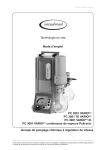
Sensor overview
①
②
③
④
⑤
⑥
Lid-lock
Cable feed-through (M12 socket or gland)
Sensor front end (DSL) (Remote configuration only)
Plug and threaded port for for example pressure guard
Sensor enclosure
Process connections
Figure 2-4
Overview, remote and compact configuration
Transmitter design
The transmitter reads the primary values from the sensor and calculates derived values. It
provides four configurable I/Os, HART communication, and a local user interface (LUI). It
also adds functionalities such as corrected volume flow, density, fractions, totalizers, dosing,
access control, diagnostics, and configuration. The local user interface consists of a display
and four buttons for user interaction.
The transmitter has a modular design with discrete, replaceable electronic modules and
connection boards to maintain separation between functions and facilitate field service. All
modules are fully traceable and their provenance is included in the transmitter setup.
SITRANS FC430 with HART
Service Manual, 12/2013, A5E03736884-02
9
Description
2.1 Design
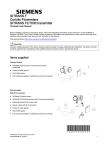
Transmitter exploded view
①
②
③
④
⑤
⑥
⑦
⑧
⑨
⑩
Display cover
⑪
Cable entry
Local user interface (LUI)
Connector for LUI
SD card (SensorFlash)
DIP switch (for custody transfer)
DIP switch (for HART)
LUI port
USB service port
Transmitter cassette
Heatsink cover for power supply
module
⑫
⑬
⑭
⑮
⑯
⑰
⑱a
⑱b
⑲a
⑲b
Transmitter housing
Terminal space
Power supply terminal protection cover
Lid for terminal connections
Wiring tool
I/O cassette (optional)
M12 socket
Terminal housing
Sensor module (compact version)
Sensor module (remote version)
SITRANS FC430 with HART
10
Service Manual, 12/2013, A5E03736884-02
Description
2.2 SensorFlash concept
2.2
SensorFlash concept
System parameters are divided into four main groups.
● Hardware setup parameters
● Production setup parameters for sensor
● Production setup parameters for transmitter
● User / Application parameters
The parameters are available in sensor and transmitter electronics.
This graphic gives an overview of which parameter groups are available in which devices,
and which groups are backed up in the SensorFlash.
SensorFlash parameter groups
The following tables show the availability of the different parameter groups and whether they
are automatically backed up or not.
Table 2- 1
Parameter groups
Parameter group
Description
Automatic backup to SensorFlash?
Hardware setup parameters
The parameters are uniqe to the
specific hardware, for example
calibration setup of the PCBa's.
No
Production setup parameters for sensor The parameters are set up in
production. They are valid for the
specific sensor that they are attached
to and include for example calibration
parameters.
Yes
SITRANS FC430 with HART
Service Manual, 12/2013, A5E03736884-02
11
Description
2.2 SensorFlash concept
Parameter group
Description
Automatic backup to SensorFlash?
Production setup parameters for
transmitter
The parameters are set up in
production. They include system
configuration parameters, for example
product name.
Yes
User / Application parameters
The parameters are for the user to
configure the device, for example
setting of empty tube (sensor) and
output scaling (transmitter). The
parameters are protected by user or
expert access level.
Yes
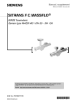
SensorFlash data
The SensorFlash data is structured on the SD card as shown here:
Figure 2-5
Table 2- 2
SensorFlash files
This table shows the individual data groups contained on the SensorFlash.
SensorFlash data group
Description
Certificates
Contains all certificates that belong to the product:
Subfolders
Product: Contains product related certificates
Project: Contains production related certificates
SEN_0.BAK,
SEN_1.BAK
The SensorFlash holds three sensor parameter backup files
to which data is written continuously.
SEN_2.BAK:
This ensures that if the device is powered down in an
unfortunate moment, there is always one valid copy of the
backup.
TRN_0.BAK
The SensorFlash holds three transmitter parameter backup
files to which data is written continuously.
TRN_1.BAK
TRN_2.BAK
This ensures that if the device is powered down in an
unfortunate moment, there is always one valid copy of the
backup.
md-3.02.00-03.fwb
FW bundle version delivered with the product
SITRANS FC430 with HART
12
Service Manual, 12/2013, A5E03736884-02
Description
2.3 Firmware update
2.3
Firmware update
Via SIMATIC PDM
1. Download the new firmware bundle from www.siemens.com/FC430
(www.siemens.com/FC430) and save it to the SensorFlash. An instruction is also
available at this site.
2. Go to "Access Management" in the "Device" dropdown menu. Sign in as "Expert" (default
password is 2834).
3. Go to "Firmware Update" in the "Device" dropdown menu and click "Install FW Version" in
order to install appropriate FW. A progress bar is shown in PDM, the device restarts and
a communication failure is reported in PDM.
4. Shut down the PDM driver and open again. Ensure to open the PDM driver compatible
with the new FW.
Note
Communication problem
If communication cannot be established after FW update, then disconnect the USB cable
from the PC and connect again.
Via LUI
1. Download the new firmware bundle from www.siemens.com/FC430
(www.siemens.com/FC430) and save it to the SensorFlash. An instruction is also
available at this site.
2. Access the flowmeter with access level Expert (the default PIN code is 2834).
3. Enter menu item 3.3.5 (FW Update), select the saved firmware bundle version and press
. The LUI displays the firmware update progress.
Note
Firmware update
FW update is to be done only by authorized and trained service personal
SITRANS FC430 with HART
Service Manual, 12/2013, A5E03736884-02
13
Description
2.3 Firmware update
SITRANS FC430 with HART
14
Service Manual, 12/2013, A5E03736884-02
3
Troubleshooting
3
Initial checking of the application
If an error or unexpected event occurs, first check that installation and commissioning
including zero point adjustment are performed as described in the Operating Instructions.
If the error persists, then go through the steps of the troubleshooting flowchart. The flowchart
and the subsections referred to in the flowchart will enable you to trace the reason for alarms
and operational instabilities.
Typical causes of incorrect measurements
Incorrect and unstable measurements, especially at low flows are typically a result of an
unstable zero point due to:
● Incorrect installation
● Bubbles in the liquid
● Vibrations/Cross talk
● Solid particles settling in the liquid
SITRANS FC430 with HART
Service Manual, 12/2013, A5E03736884-02
15
Troubleshooting
3.1 Troubleshooting overview
3.1
Troubleshooting overview
This flowchart offers and overview of the necessary procedure to identify and remedy errors.
Follow the steps in the flowchart and find more information in the sections referred to in the
gray boxes marked A1 etc.
Figure 3-1
* "Process value" alarms correspond to "Out of specification" alarms if the display is set
to NAMUR standard.
SITRANS FC430 with HART
16
Service Manual, 12/2013, A5E03736884-02
Troubleshooting
3.2 Clear alarms and system messages (A1)
3.2
Clear alarms and system messages (A1)
Take action to clear alarms and system messages as described in Alarms and system
messages (Page 29)
The alarms should be cleared in a sequence according to the alarm class. Depending on
alarm standard, Siemens or NAMUR, the sequence is as follows:
Table 3- 1
Sequence of alarms
Alarm class
Siemens standard
NAMUR standard
Function check:
alarms including incompatible firmware
or hardware
Configuration changed
Check function
Failure or Maintenance alarm
Maintenance alarm
Failure
Process value alarm
Out of specification
Process value alarm/warning or Out of
specification
Process value warning
3.3
Prove correct sizing and calculate measurement error (A2)
If the flowmeter gives unstable measurements and there are no alarms or the alarms are of
the type "Process Value alarms", then sizing of the application must be proven. This is done
two steps:
1. Prove correct sizing (Page 18)
2. Calculate measurement error (Page 19)
SITRANS FC430 with HART
Service Manual, 12/2013, A5E03736884-02
17
Troubleshooting
3.3 Prove correct sizing and calculate measurement error (A2)
3.3.1
Prove correct sizing
Use the sizing program to check if the coriolis sensor is sized correctly. The sizing program
is available for download or for online use from the PIA Lifecycle Portal at https://www.piaportal.automation.siemens.com/default.htm
(https://www.pia-portal.automation.siemens.com/default.htm).Select language and click the
tab "Sizing" followed by "Start".
Figure 3-2
SITRANS FC Sizing Program
Checking the sizing
Using the sizing program, examine if the coriolis sensor is sized correctly by checking the
flow velocity. The range should be within 0.01 to 20 m/s.
● If the flow velocity is very low, consider replacing the sensor with a smaller size.
● If the flow velocity very high, consider cavitation or bubble release within the sensor.
Increase the process pressure.
SITRANS FC430 with HART
18
Service Manual, 12/2013, A5E03736884-02
Troubleshooting
3.3 Prove correct sizing and calculate measurement error (A2)
3.3.2
Calculate measurement error
The result of the zero point adjustment will show you if the zero point was set under good
and stable conditions. The lower the obtained value of the parameter "Zero Point Standard
Deviation", the lower is the achievable measuring error. For a well-installed flowmeter, the
Zero Point Standard Deviation corresponds to the specified zero point stability for the sensor
size, see Technical specifications in the Operating instructions.
The parameter "Zero Point Standard Deviation" is located in the "Maintenance &
Diagnostics" menu in the SIMATIC PDM and the LUI display. If the flowmeter still gives
wrong or unstable measurements, the next step is to perform a mass balance calculation.
Calculation formula
Given the Zero Point Standard Deviation, the error expected for different flow rates can be
calculated, without performing time-consuming measurements. So using this formula, one
can assess if the application can be used as–is, or whether to use more time improving the
installation.
E
=
Z x 100 % / Qm
where:
E
=
measurement error in % of flowrate
Z
=
zero point standard deviation value in kg/h
Qm =
current flowrate in kg/h
Example 1: Low flow application
● DN 15 sensor: The sensor's nominal flowrate is specified to 3700 kg/h
● Zero point error (Zero Point Standard Deviation) value is specified as 0.2 kg/h
● Flow: Min. 10 kg/h - Max. 100 kg/h
After the zero point adjustment, the Zero Point Standard Deviation value 'Z' is read as 1 kg/h,
that is 5 times greater than that specified for the sensor.
The error for a flowrate of 10 kg/h is estimated as:
● E = 1 kg/h x 100% / 10 kg/h = 10%.
For a flowrate of 100 kg/h the error is estimated as:
● E = 1 kg/h x 100% / 100 kg/h = 1%
For this application it is necessary to investigate more closely what the cause of the relatively
high Zero Point Standard Deviation value is, in order to establish what needs to be done to
improve the measurement accuracy.
SITRANS FC430 with HART
Service Manual, 12/2013, A5E03736884-02
19
Troubleshooting
3.4 Inspect the application (A3)
Example 2: High flow application
DN 15 sensor: The sensor flowrate is specified as max. 3700 kg/h
● The zero point error/ Zero Point Standard Deviation value is specified as 0.2 kg/h
● Flowrate: Min. 1000 kg/h - Max. 3000 kg/h
After the zero point adjustment, the Zero Point Standard Deviation value 'Z' is read as 1 kg/h,
that is 5 times greater than specified for the sensor !
The error at a flowrate of 1000 kg/h is estimated as:
● E = 1 kg/h x 100% / 1000 kg/h = 0.1%
At a flowrate of 3000 kg/h the error is estimated to be:
● E = 1 kg/h x 100% / 3000 kg/h = 0.03%
Plus the linearity error of 0.1%
As can be seen, in this case it is not so important that the standard deviation is 1 kg/h. The
error due to the zero point is only 0.1% for a flowrate of 1000 kg/h, and even less for a higher
flowrate.
So for this installation with the given flowrate and zero point error (Zero Point Standard
Deviation value), you should typically choose not to spend more time finding ways to
improve the application.
3.4
Inspect the application (A3)
If the flowmeter still gives unstable measurements or process value alarm(s) persist, then go
through the following inspection steps or see if you can find help in the examples shown in
the table First of all ensure that:
1. The sensor is installed as described in the Operating Instructions.
2. The sensor is located in a vibration-free position. Vibrations can disturb the sensor and
therefore cause measurement errors.
Depending on application, you should furthermore ensure the following:
● Liquid application
Ensure that the sensor is filled with liquid and liquid only.
Air or gas bubbles in the liquid cause instability and can result in measurement errors.
Flush the pipe systems and the sensor for several minutes at maximum flowrate to
remove any air bubbles which may be present.
Note
The liquid must be homogeneous in order to measure with high accuracy. If the liquid
contains solid particles of greater density than the liquid, then these solids can settle,
especially at low flow rates, which will cause instability in the sensor and lead to
measurement errors.
● Gas application
Ensure that the gas pressure/temperature conditions contain sufficient superheat to
prevent dewing or precipitation. If the gas contains vapor or droplets then these may
precipitate, causing instability.
SITRANS FC430 with HART
20
Service Manual, 12/2013, A5E03736884-02
Troubleshooting
3.4 Inspect the application (A3)
Application inspection examples
The following examples, possible causes and suggestions for corrective action may give the
answer to why the application is unstable.
Problem
Possible causes
Remedy
The flowmeter indicates higher or
significantly lower values than actual
flow rate
• Cavitation
• Increase back pressure.
• Build-up of foreign material in
flowmeter bore
• Clean flowmeter.
• Gas in the liquid
Unstable flow signal
• Mechanical vibrations effect
- with closed valve, i.e. zero flow and/or oscillation of coriolis flowmeter at zero
flow.
- abort of zero point adjustment / zero
point adjustment not possible
• Leak
• Gas in liquid
• Wrong installation
• Install gas eliminator ahead of
flowmeter.
• Make sure that the shut-off valve is
completely closed.
• Make sure that the sensor has been
correctly built in.
• Check the driver signal to ensure that
the medium does not contain air
bubbles.
• Check for vibrations, cross-talk and
physical stress.
System works perfect except indicates
lower flow over the entire range
• By-pass flow
Display shows temperature of
approximately -240 °C, however, the
media temperature is approximately 20
°C
• Temperature sensor has failed
• Check resistance of PT1000 sensors
at the sensor connector of wiring to the
PT1000 sensor, see PT1000 resistance
table.
The display shows negative density,
however the medium is gas with a
density of approximately 5 kg/m3
• Wrong order code or calibration
• Make sure that the sensor has been
calibrated for density. If yes, check the
sensor frequency. Too high sensor
frequency will result in negative density
readings.
• Leak
• Repair or replace by-pass valves, or
faulty solenoid valves.
Contact Siemens.
The flowmeter fails to measure
• Solid particles are settling in the tubes • The flowmeter must be installed in
vertical position with flow upwards to
• High concentration of solutions
ensure that the tubes are properly
precipitation
cleared.
SITRANS FC430 with HART
Service Manual, 12/2013, A5E03736884-02
21
Troubleshooting
3.5 Check sensor specific data (A4)
Figure 3-3
3.5
PT1000 resistance table
Check sensor specific data (A4)
If the measurements are still unsatisfactory, the sensor diagnostic values should be checked.
This is done in two steps:
1. Verify sensor diagnostic parameters (Page 22)
2. Measure resistance on sensor connector (Page 25)
3.5.1
Verify sensor diagnostic parameters
The diagnostic values of the sensor are shown in the LUI diagnostic view. The LUI provides
six configurable measurement/diagnostic values that are updated dynamically.
Figure 3-4
Diagnostic view
SITRANS FC430 with HART
22
Service Manual, 12/2013, A5E03736884-02
Troubleshooting
3.5 Check sensor specific data (A4)
Diagnostic and process values may also be checked through PDM in a bar graph or on a
trend curve.
Figure 3-5
PDM graphic view
Diagnostic values
The values (except the pickup amplitude) are dependent on the media density. The values
listed in the table are nominal values (for air and water).
Check if the values shown in PDM under "Maintenance and Diagnostics" → "Diagnostics" are
within range of the values shown in the table.
SITRANS FC430 with HART
Service Manual, 12/2013, A5E03736884-02
23
Troubleshooting
3.5 Check sensor specific data (A4)
Table 3- 2
Size
Diagnostic values
Driver current [mA]
Pick-up voltage
[mV]
Sensor frequency
Empty (air) [Hz]
Filled with
water [Hz]
Standard deviation
[kg/h]
DN15*
2.5-3.7
60-70
690
605
± 0.2
DN25*
2.1-3.1
60-70
720
615
± 0.2
DN50*
2.3-3.2
60-70
580
480
± 0.2
DN80*
1.9-2.2
60-70
370
310
± 0.2
* Driver current can be up till:
● Release 1: 15 mA rms
● Release 2: 30-35 mA rms
Examples of diagnostic values that are out of range
The following examples show sensor diagnostic parameters that are out of range and
suggest corrective action.
Example 1: (DN 15)
1. Driver current: 12 mA
2. Pick-up 1 voltage: 35 mV
3. Pick-up 2 voltage: 34 mV
4. Sensor frequency: 400 Hz
Conclusion: Pick-up voltage is low due to high density or small bubbles releasing in the fluid.
Action: Improve application (Page 26)
Example 2: (DN 25)
1. Driver current: 3-6 mA
2. Pick-up 1 voltage: 65 mV
3. Pick-up 2 voltage: 65 mV
4. Sensor frequency: 580-615 Hz
Further information: Sensor and frequency fluctuate regularly
Conclusion: Slug flow caused by poor mixing, for example oil-water-oil-water flowing in
sequence
Action: Relocate flowmeter to position where fluid is already mixed.
See also
Measure resistance on sensor connector (Page 25)
Check sensor specific data (A4) (Page 22)
SITRANS FC430 with HART
24
Service Manual, 12/2013, A5E03736884-02
Troubleshooting
3.5 Check sensor specific data (A4)
3.5.2
Measure resistance on sensor connector
Checking the sensor resistance will indicate if the sensor is in good working condition. The
sensor resistance values can be measured directly on the connector.
Connector pins
Figure 3-6
Sensor cable connector pins
This table shows the designations of the 10 pins of the sensor connector
Table 3- 3
Connector pins
Pin
Color
Description
Pick-up 1
PIN 1
P1+
Orange
PIN 2
P1-
Green
PIN 3
P2+
White
PIN 4
P2-
Blue
PIN 5
T1
Yellow
PIN 6
T2
Yellow
PIN 7
T3
Red
PIN 8
T4
Red
PIN 9
D1+
Brown
PIN 10
D1-
Black
Pick-up 2
Tube temperature PT1000
Frame temperature PT1000
Driver
SITRANS FC430 with HART
Service Manual, 12/2013, A5E03736884-02
25
Troubleshooting
3.6 Improve the application (A5)
Sensor resistance values
Check if the measured resistance values are within range of the values shown in this table.
Table 3- 4
Sensor resistance values
Size
Driver resistance at 20
°C [Ω]
Driver resistance at
200 °C [Ω]
Pick-up resistance at
20 °C [Ω]
Pick-up resistance at
200 °C [Ω]
DN15
3.1±0.06
∼4.5
95.9±3
157.2±16
DN25
23.7±0.35
∼36.9
95.9±3
157.2±16
DN50
44.9±0.73
∼72.2
95.9±3
157.2±16
DN80
37.1±0.69
∼60.8
95.9±3
157.2±16
3.6
Improve the application (A5)
If the application still gives unstable or incorrect measurements, a number of measures can
be taken to improve the installation. In the following it is described how to find the causes of
a high Zero Point Standard Deviation and other measures that will improve the installation.
Setting Low Flow Cut-Off
In order to see if the zero point becomes more stable when making changes / adjustments,
the Low Mass Flow Cut-Off (MassFlowCutOff) must be set to 0.0%.
When Low Flow Cut-Off has been set, it is possible to see the instability directly from the
massflow in the online window ("View → Process variables")
This information can be used to troubleshoot. For example, tightening the brackets which
hold the sensor, or turning off the pump to check if vibrations from the pump are disturbing
the sensor, etc.
Incorrect installation of the sensor
Has the sensor been correctly installed, that is fastened to the floor / wall or frame with good
mounting brackets as shown in the instructions?
Especially for low flowrates, that is flowrates less than 10% of the maximum capacity of the
flow meter, it is important that the sensor is correctly and stably installed.
If the sensor is not correctly fixed in place, the zero point of the sensor will change, leading
to measuring errors.
Try to tighten up the sensor brackets to see whether the flow instability is reduced.
SITRANS FC430 with HART
26
Service Manual, 12/2013, A5E03736884-02
Troubleshooting
3.6 Improve the application (A5)
Vibrations and cross talk
Vibrations in the pipe system are normally generated by pumps.
Typically, cross talk is generated by two sensors of the same size positioned in close
proximity in the same pipe, or installed upon the same rail or frame.
Vibrations / cross talk have a greater or lesser effect upon the zero point stability and
therefore also the measurement accuracy.
1. Check whether there are vibrations.
Turn off the pump and check whether the zero point stability improves, that is if the
flowrate fluctuation in kg/h is reduced.
If the sensor is disturbed by vibration from the pump, the installation should be improved
or the pump should be exchanged, for example to another type.
2. Check for cross talk.
Turn off the power to the other flow meter(s) and wait approximately 2 minutes, so the
vibrating tubes in the sensor have stopped vibrating. Then check if the zero point stability
has improved, that is that the fluctuation in kg/h has been reduced. If this is the case, the
sensors disturb one another and the installation should be improved.
Air in the liquid
When air is present in the liquid, the zero point becomes unstable, which leads to a poor
measurement accuracy.
Checking for air:
● Check the Driver Current (View → Device Status → Amplitude / Frequency (menu item
3.4.2.1))
● Check if the Driver Current varies more than ±1 mA. If this is the case, it is usually due to
the presence of air or gas bubbles in the liquid.
● Increase the pressure in the sensor, creating a large back pressure upon the sensor by
reducing the opening of the outlet valve or by increasing the pump pressure. Thereby the
size of air bubbles inside the sensor will be minimized. The Driver Current stability will
increase with reduced air bubble size or amount in the liquid.
Typical causes of air in the liquid
● The entry pipe and sensor have not been properly filled with liquid.
● The pump cavitates, the rotary speed of the pump is too high in relation to the supply of
liquid to the pump.
● The flow rate in the pipe is too high, so components installed upstream of the flowmeter
can cause cavitation.
● If there is a filter installed upstream of the flowmeter, it may be close to blocking, which
also can cause cavitation.
● Liquid flashes to vapor bubbles while passing through partially open valves or orifices.
SITRANS FC430 with HART
Service Manual, 12/2013, A5E03736884-02
27
Troubleshooting
3.6 Improve the application (A5)
Solid particles in the liquid
If the solid particles in a liquid have a density higher than that of the liquid, they may
precipitate inside the sensor and cause instability leading to a measurement error. However,
if the solid particles are small in size and the flowrate is high, the particles may simply be
flushed through the sensor, even if their density is larger than the fluid density.
It is important that the sensor is installed such that solid particles can easily run out of the
sensor.
1. Ensure that the sensor is installed vertically with an upwards flow.
2. Check if solid particles are present in the liquid:
Take a sample of the liquid, fill a glass and see if the solids precipitate.
SITRANS FC430 with HART
28
Service Manual, 12/2013, A5E03736884-02
4
Alarms and system messages
4.1
4
Overview of messages and symbols
This section describes alarm messages shown on the LUI display.
Display behavior on local user interface
Messages are shown in the operation view of the display.
● Operation view shows the alarms as a combination of symbol and text in the lower line of
the display. If several diagnostic messages are active at the same time, the most critical
is always shown.
● Alarm list view shows all active alarms on a list. The alarm list combines a symbol, text
and an alarm ID number. The most recent alarm is shown on top of the list. The alarm list
view can also be accessed via menu item 3.3.2 Alarm.
● Alarm history view lists the most recent alarms (up to 100). The alarm history log can be
viewed in menu item 3.2.3. The alarm history log can be reset in menu item 3.2.4.
Characteristics of messages
The device provides two types of alarm classes, NAMUR and Siemens standard, selected in
menu item 3.2.1 Alarm Mode.
The following tables summarize the two types of alarm classes in an overview.
The sequence of the symbols corresponds to the priority of the messages, beginning with
the most critical.
Siemens standard alarm classes
The number of dots assigned to the symbol defines the importance level of the message.
Table 4- 1
Icon
Siemens standard icons
Alarm class
Definition
Maintenance alarm
The device outputs fault current.
Service the device immediately.
Function check
Output signal temporarily invalid (for example frozen) due to on-going work on the
device.
SITRANS FC430 with HART
Service Manual, 12/2013, A5E03736884-02
29
Alarms and system messages
4.2 Alarm messages
Process value alarm
The device outputs a fault current or is at the limit of the saturation range.
Process value warning
There is a problem with one or more process values. Thus the device is still
measuring process values, but these may be unreliable.
Example: A process value exceeds the device specification.
NAMUR alarm classes
Table 4- 2
Icon
4.2
NAMUR icons
Alarm classes
Definition
Failure
Output signal invalid due to malfunction in the field device or its peripherals.
Out of specification
"Off-spec" means that the device is operating outside its specified range (for example
measuring or temperature range) or that internal diagnoses indicate deviations from
measured or set values due to internal problems in the device or process
characteristics (for example compressible emulsions in the process medium).
Function check
Output signal temporarily invalid (for example frozen) due to on-going work on the
device.
Alarm messages
Alarms and system messages support both Siemens standard and NAMUR.
In the following tables the alarm ID (identification number) can be found along with possible
causes and directions for corrective action. The alarm may affect the output depending on
the process value selected to be signaled on the output as listed in the following tables.
● Yes: The output is affected if the process value to be signaled is: Massflow (and
Corrected Volumeflow), Volumeflow, Density or Temperature.
● Yes*: The output is affected if the process value to be signaled is: Massflow (and
Corrected Volumeflow), Volumeflow, or Density.
Alarm classes:
Maintenance alarm (Siemens standard),
Failure (NAMUR)
ID
Diagnostic
Action
32
SIL parameters not validated
Run the "Safety Validation" wizard to validate the safety-critical
parameters. The device can be put into Safe Operation mode
after validation.
Sensor external supply volt. out of
range
Replace the power supply unit in the transmitter, see Replaceable Yes
components (Page 45)
33
34
Effect on
output
35
36
SITRANS FC430 with HART
30
Service Manual, 12/2013, A5E03736884-02
Alarms and system messages
4.2 Alarm messages
ID
Diagnostic
Action
Effect on
output
37
Sensor analog supply volt. out of
range
Replace the sensor electronic (remote version DSL cassette or
compact version sensor interface cassette), see Replaceable
components (Page 45)
Yes
38
39
40
41
Temperature measurement fault
Go through one or more of the following steps until the error is
corrected and the alarm disappears:
Yes
1. Turn off the power, wait 5 seconds and turn on the power
again. If the alarm continues, the sensor electronic may be
defective.
2. Replace the sensor electronic (remote version DSL cassette
or compact version sensor interface cassette), see
Replaceable components (Page 45)
46
Invalid calibration data
47
Check if customer calibration settings are out of range for the
application. Note down current parameter values before you
change any of the values.
Yes*
Go through one or more of the following steps until the error is
corrected and the alarm disappears:
1. If manual zero point adjustment is enabled (Menu item 2.6.1),
then set Offset to zero (menu item 2.6.8).
2. Log in as Expert, and reconfigure the following user calibration
parameters:
–
In menu item 2.2.4."Flow Adjustment", set "Adjustment
Factor" to "1".
–
In menu item 2.2.5.10 "Density Adjustment", set
"Adjustment Factor" to "1" and "Adjustment Offset" to "0".
3. Check if calibration factor (menu item 3.5.6.3) matches the
calibration factor from the calibration certificate. If not, then
recalibrate the sensor by restoring sensor calibration
parameters from the SensorFlash
4. If the error continues, send the device to factory for
recalibration.
49
50
51
Malfunction in Pickup Amplitude
55
56
57
Malfunction in sensor driver
58
Unstable driver oscillation
The sensor electronic is defective or a pickup is damaged.
Yes*
Replace the sensor electronic (remote version DSL cassette or
compact version sensor interface cassette). If the alarm
continues, then replace the sensor, see Replaceable components
(Page 45).
The circuitry may be damaged resulting in high amplitude.
Yes*
Replace the sensor electronic (remote version DSL cassette or
compact version sensor interface cassette), see Replaceable
components (Page 45).
If operation is within specifications and no other alarms are
signaled, the sensor electronic may be defective.
Yes*
Go through one or more of the following steps until the error is
corrected and the alarm disappears:
1. Check the connection between driver and sensor electronic.
2. Replace the sensor mechanic.
SITRANS FC430 with HART
Service Manual, 12/2013, A5E03736884-02
31
Alarms and system messages
4.2 Alarm messages
ID
Diagnostic
Action
Effect on
output
71
Parameter storage malfunction
Go through one or more of the following steps until the error is
corrected and the alarm disappears:
1. Turn off the power, wait 5 seconds and turn on the power
again. If the alarm continues, the sensor electronic may be
defective.
2. Replace the sensor electronic (remote version DSL cassette
or compact version sensor interface cassette), see
Replaceable components (Page 45).
72
73
74
75
76
Internal error in sensor
Replace the sensor electronic (remote version DSL cassette or
compact version sensor interface cassette), see Replaceable
components (Page 45)
Yes
87
The sensor is stabilizing
Go through one or more of the following steps until the error is
corrected and the alarm disappears.
Yes
Remote variant
1. Turn off the power. Unplug and reconnect the sensor cable.
Restore power and wait 20 seconds.
2. Power failure:
Check if the voltage at DSL connector within range (9-16 V
DC).
If yes, go to step 3.
If not one or more of the following actions should be taken:
–
Replace power cable.
–
Replace sensor interface module
–
Replace power supply
–
See Replaceable components (Page 45)
3. Communication failure:
–
Check for cable break or bad connection on the AB
Modbus connection
–
Measure between AB and housing (ground)
4. Replace sensor electronics, see Replaceable components
(Page 45)
Compact variant
1. Turn off the power. Unplug and reconnect the sensor cable.
Restore power and wait 20 seconds.
2. Replace sensor interface module.
3. Replace power supply.
See Replaceable components (Page 45)
150
Sensor signal disrupted
Turn off the power. Unplug and reconnect the sensor cable.
Restore power and wait 20 seconds. If the alarm continues, the
sensor electronic may be defective.
Replace the sensor electronic (remote version DSL cassette or
compact version sensor interface cassette), see Replaceable
components (Page 45).
SITRANS FC430 with HART
32
Service Manual, 12/2013, A5E03736884-02
Alarms and system messages
4.2 Alarm messages
ID
Diagnostic
Action
157
Safety alarms
The system has detected a safety-related alarm in Safe
Operation. The device is in safety alarm state. All alarms must be
cleared to bring the unit to Safe Operation mode. See manual
"Functional Safety for SITRANS FC430"
158
HART cable break
Check channel 1 current output cable connection.
159
Internal error in transmitter
Turn off the power, wait 5 seconds and turn on the power again. If
the alarm continues, then check if other alarms are signaled.
Effect on
output
If operation is within specifications and no other alarms are
signaled, a systematic error may have occurred in the transmitter
electronic.
Contact factory service and support and provide alarm ID found in
submenu of Internal error in transmitter.
171
Product FW incompatible
Update rejected - product firmware update failed.
Check firmware revision in Replaceable components (Page 45)
172
Transm. FW incompatible
Update rejected - transmitter FW incompatible. Firmware update
failed.
Check firmware revision in Compatibility check mechanic spare
parts (Page 51)
173
Sensor FW incompatible
Update rejected - sensor FW incompatible. Firmware update
failed.
Check firmware revision in Compatibility check mechanic spare
parts (Page 51)
174
LUI FW incompatible
Update rejected - sensor FW incompatible. Firmware update
failed.
Check firmware revision in Compatibility check mechanic spare
parts (Page 51)
197
Current output cable break
Check channel 2 current output cable connection
203
Current output cable break
Check channel 3 current output cable connection
209
Current output cable break
Check channel 4 current output cable connection
213
Invalid dosing configuration
The Two Stage Dosing controls two valves with use of two Signal
Outputs. To ensure valid configuration either Stage 1 Primary
Open or Stage 2 Secondary Open must be set to 0 and either
Stage 1 Primary Close or Stage 2 Secondary Close must be set
to Amount
SITRANS FC430 with HART
Service Manual, 12/2013, A5E03736884-02
33
Alarms and system messages
4.2 Alarm messages
Alarm classes:
Process value alarm (Siemens standard),
Out of specification (NAMUR)
ID
Diagnostic
Action
Effect on
output
42
43
44
45
Flow values not valid
Can be due to problems with measured fluid or hardware
malfunction. If operation is within specifications and no other
alarms are signaled, then contact factory service and support.
59
Massflow out of specification
If operation is within specifications and no other errors are
signaled, the sensor electronic or the mechanical sensor may be
defective.
Go through one or more of the following steps until the error is
corrected and the alarm disappears:
1. Reduce the flow.
2. Fix other errors.
3. Replace the sensor electronic (remote version DSL cassette
or compact version sensor interface cassette)
4. Replace the sensor mechanic.
See Replaceable components (Page 45)
60
Volumeflow out of specification
If operation is within specifications and no other errors are
signaled, the sensor electronic or the mechanical sensor may be
defective.
Go through one or more of the steps below until the error is
corrected and the alarm disappears:
1. Reduce the flow.
2. Fix other errors.
3. Replace the sensor electronic (remote version DSL cassette
or compact version sensor interface cassette)
4. Replace the sensor mechanic.
See Replaceable components (Page 45)
61
Density out of specification
If operation is within specifications and no other alarms are
signaled, the sensor electronic or the mechanical sensor may be
defective.
Go through one or more of the steps below until the error is
corrected and the alarm disappears:
1. Reduce the flow.
2. Fix other errors.
3. Replace the sensor electronic (remote version DSL cassette
or compact version sensor interface cassette)
4. Replace the sensor mechanic.
See Replaceable components (Page 45)
SITRANS FC430 with HART
34
Service Manual, 12/2013, A5E03736884-02
Alarms and system messages
4.2 Alarm messages
ID
Diagnostic
Action
62
Fluid temp. below limit
If operation is within specifications and no other errors are
signaled, the sensor electronic or the mechanical sensor may be
defective.
Effect on
output
Go through one or more of the steps below until the error is
corrected and the alarm disappears:
1. Increase the fluid temperature.
2. Fix other errors.
3. Replace the sensor electronic (remote version DSL cassette
or compact version sensor interface cassette)
4. Replace the sensor mechanic.
See Replaceable components (Page 45)
63
Fluid temp. above limit
If operation is within specifications and no other errors are
signaled, the sensor electronic or the mechanical sensor may be
defective.
Go through one or more of the steps below until the error is
corrected and the alarm disappears:
1. Reduce the fluid temperature.
2. Fix other errors.
3. Replace the sensor electronic (remote version DSL cassette
or compact version sensor interface cassette)
4. Replace the sensor mechanic.
See Replaceable components (Page 45)
64
Frame temp. below limit
If operation is within specifications and no other errors are
signaled, the sensor electronic or the mechanical sensor may be
defective.
Go through one or more of the steps below until the error is
corrected and the alarm disappears:
1. Increase fluid temperature and check that ambient
temperature is within specified limits.
2. Fix other errors.
3. Replace the sensor electronic (remote version DSL cassette
or compact version sensor interface cassette)
4. Replace the sensor mechanic.
See Replaceable components (Page 45)
65
Frame temp. above limit
If operation is within specifications and no other errors are
signaled, the sensor electronic or the mechanical sensor may be
defective.
Go through one or more of the steps below until the error is
corrected and the alarm disappears:
1. Reduce fluid temperature and check that ambient temperature
is within specified limits.
2. Fix other errors.
3. Replace the sensor electronic (remote version DSL cassette
or compact version sensor interface cassette)
4. Replace the sensor mechanic.
See Replaceable components (Page 45)
SITRANS FC430 with HART
Service Manual, 12/2013, A5E03736884-02
35
Alarms and system messages
4.2 Alarm messages
ID
Diagnostic
Action
Effect on
output
69
"Empty Tube Limit" exceeded
Make sure that the sensor is filled with liquid and that the liquid
density is within the specified "Empty Tube Limit"
78
Unstable measurement condition
Check if air is present in the liquid and that the flowmeter is
operated within its specifications.
79
Auto filtering
Check that the flowmeter is operated within its specifications.
Check other alarms to rule out HW malfunction.
96
Massflow above alarm limit
Check process conditions or align limit to normal operation.
Adjust parameter "Upper Limit Alarm".
99
Massflow below alarm limit
Check process conditions or align limit to normal operation.
Adjust parameter "Lower Limit Alarm".
100
Volumeflow above alarm limit
Check process conditions or align limit to normal operation.
Adjust parameter "Upper Limit Alarm".
103
Volumeflow below alarm limit
Check process conditions or align limit to normal operation.
Adjust parameter "Lower Limit Alarm".
104
Density above alarm limit
Check process conditions or align limit to normal operation.
Adjust parameter "Upper Limit Alarm".
107
Density below alarm limit
Check process conditions or align limit to normal operation.
Adjust parameter "Lower Limit Alarm".
108
Fluid temp. above alarm limit
Check process conditions or align limit to normal operation.
Adjust parameter "Upper Limit Alarm".
111
Fluid temp. below alarm limit
Check process conditions or align limit to normal operation.
Adjust parameter "Lower Limit Alarm".
112
Fraction A % above alarm limit
Check process conditions or align limit to normal operation.
Adjust parameter "Upper Limit Alarm".
115
Fraction A % below alarm limit
Check process conditions or align limit to normal operation.
Adjust parameter "Lower Limit Alarm".
116
Fraction B % above alarm limit
Check process conditions or align limit to normal operation.
Adjust parameter "Upper Limit Alarm"
119
Fraction B % below alarm limit
Check process conditions or align limit to normal operation.
Adjust parameter "Lower Limit Alarm".
120
Fract. A flow above alarm limit
Check process conditions or align limit to normal operation.
Adjust parameter "Upper Limit Alarm".
123
Fract. A flow below alarm limit
Check process conditions or align limit to normal operation.
Adjust parameter "Lower Limit Alarm".
124
Fract. B flow above alarm limit
Check process conditions or align limit to normal operation.
Adjust parameter "Upper Limit Alarm".
127
Fract. B flow below alarm limit
Check process conditions or align limit to normal operation.
Adjust parameter "Lower Limit Alarm".
128
Ref. density above alarm limit
Check process conditions or align limit to normal operation.
Adjust parameter "Upper Limit Alarm".
131
Ref. density below alarm limit
Check process conditions or align limit to normal operation.
Adjust parameter "Lower Limit Alarm".
132
Corr. vol. above limit
Check process conditions or align limit to normal operation.
Adjust parameter "Upper Limit Alarm".
135
Corr. vol below alarm limit
Check process conditions or align limit to normal operation.
Adjust parameter "Lower Limit Alarm".
SITRANS FC430 with HART
36
Service Manual, 12/2013, A5E03736884-02
Alarms and system messages
4.2 Alarm messages
ID
Diagnostic
Action
136
Totalizer 1 above alarm limit
Check process conditions or align limit to normal operation.
Adjust parameter "Upper Limit Alarm".
139
Totalizer 1 below alarm limit
Check process conditions or align limit to normal operation.
Adjust parameter "Lower Limit Alarm".
140
Totalizer 2 above alarm limit
Check process conditions or align limit to normal operation.
Adjust parameter "Upper Limit Alarm".
143
Totalizer 2 below alarm limit
Check process conditions or align limit to normal operation.
Adjust parameter "Lower Limit Alarm".
144
Totalizer 3 above alarm limit
Check process conditions or align limit to normal operation.
Adjust parameter "Upper Limit Alarm".
147
Totalizer 3 below alarm limit
Check process conditions or align limit to normal operation.
Adjust parameter "Lower Limit Alarm".
148
Transm. temp. above alarm limit
Check process conditions or align limit to normal operation.
Adjust parameter "Upper Limit Alarm".
149
Transm. temp. below alarm limit
Check process conditions or align limit to normal operation.
Adjust parameter "Lower Limit Alarm".
153
Current output below Scaling
Check process conditions or align limit to normal operation.
Adjust channel 1 parameter "Lower Scaling".
154
Current output above Scaling
Check process conditions or align limit to normal operation.
Adjust channel 1 parameter "Upper Scaling".
192
Dosing time overrun
Check installation. If ok, increase "Duration Time".
193
Dosing quantity overrun
Check installation. If ok, decrease "Overrun Value".
194
Invalid proc. val. during dosing
Check installation for abnormal operating conditions. If the failure
continues for several dosings, contact factory service and support
195
Current output below Scaling
Check process conditions or align limit to normal operation.
Adjust channel 2 parameter "Lower Scaling".
196
Current output above Scaling
Check process conditions or align limit to normal operation.
Adjust channel 2 parameter "Upper Scaling".
198
Frequency output below Scaling
Check process conditions or align limit to normal operation.
Adjust channel 2 parameter "Flow Value Low".
199
Frequency output above Scaling
Check process conditions or align limit to normal operation.
Adjust channel 2 parameter "Flow Value High".
200
Pulse overflow
Pulse output insufficient pulse separation. Increase "Amount Per
Pulse" or reduce "Pulse Width" on channel 2.
201
Current output below Scaling
Check process conditions or align limit to normal operation.
Adjust channel 3 parameter "Lower Scaling".
202
Current output above Scaling
Check process conditions or align limit to normal operation.
Adjust channel 3 parameter "Upper Scaling".
204
Frequency output below Scaling
Check process conditions or align limit to normal operation.
Adjust channel 3 parameter "Flow Value Low".
205
Frequency output above Scaling
Check process conditions or align limit to normal operation.
Adjust channel 3 parameter ""Flow Value High".
206
Pulse overflow
Pulse output insufficient pulse separation. Increase "Amount Per
Pulse" or reduce "Pulse Width" on channel 3.
207
Current output below Scaling
Check process conditions or align limit to normal operation.
Adjust channel 4 parameter "Lower Scaling".
Effect on
output
SITRANS FC430 with HART
Service Manual, 12/2013, A5E03736884-02
37
Alarms and system messages
4.2 Alarm messages
ID
Diagnostic
Action
208
Current output above Scaling
Check process conditions or align limit to normal operation.
Adjust channel 4 parameter "Upper Scaling".
210
Frequency output below Scaling
Check process conditions or align limit to normal operation.
Adjust channel 4 parameter "Flow Value Low".
211
Frequency output above Scaling
Check process conditions or align limit to normal operation.
Adjust channel 4 parameter ""Flow Value High".
212
Pulse overflow
Pulse output insufficient pulse separation. Increase "Amount Per
Pulse" or reduce "Pulse Width" on channel 4.
Alarm class:
Process value warning (Siemens standard),
Effect on
output
Out of specification (NAMUR)
ID
Diagnostic
Action
66
"Standard Deviation" above limit
Measurement continues with values from last successful zero
point adjustment. Improve conditions for automatic zero point
adjustment and repeat adjustment.
(shown for only 2 seconds)
67
"Zero Point Offset" above limit
(shown for only 2 seconds)
68
Zero point adjustment failed
(shown for only 2 seconds)
Effect on
output
Measurement continues with values from last successful zero
point adjustment. Improve conditions for automatic zero point
adjustment and repeat adjustment.
Measurement continues with values from last successful zero
point adjustment. Improve conditions for automatic zero point
adjustment and repeat adjustment.
97
Massflow above warning limit
Check process conditions or align limit to normal operation.
Adjust parameter "Upper Limit Warning".
98
Massflow below warning alarm limit
Check process conditions or align limit to normal operation.
Adjust parameter "Lower Limit Warning".
101
Volumeflow above warning limit
Check process conditions or align limit to normal operation.
Adjust parameter "Upper Limit Warning".
102
Volumeflow below warning limit
Check process conditions or align limit to normal operation.
Adjust parameter "Lower Limit Warning".
105
Density above warning limit
Check process conditions or align limit to normal operation.
Adjust parameter "Upper Limit Warning".
106
Density below warning limit
Check process conditions or align limit to normal operation.
Adjust parameter "Lower Limit Warning".
109
Fluid temp. above warning limit
Check process conditions or align limit to normal operation.
Adjust parameter "Upper Limit Warning".
110
Fluid temp. below warning limit
Check process conditions or align limit to normal operation.
Adjust parameter "Lower Limit Warning".
113
Fraction A % above warning limit
Check process conditions or align limit to normal operation.
Adjust parameter "Upper Limit Warning".
114
Fraction A % below warning limit
Check process conditions or align limit to normal operation.
Adjust parameter "Lower Limit Warning".
117
Fraction B % above warning limit
Check process conditions or align limit to normal operation.
Adjust parameter "Upper Limit Warning".
118
Fraction B % below warning limit
Check process conditions or align limit to normal operation.
Adjust parameter "Lower Limit Warning".
SITRANS FC430 with HART
38
Service Manual, 12/2013, A5E03736884-02
Alarms and system messages
4.2 Alarm messages
ID
Diagnostic
Action
121
Fraction A flow above warning limit
Check process conditions or align limit to normal operation.
Adjust parameter "Upper Limit Warning".
122
Fraction A flow below warning limit
Check process conditions or align limit to normal operation.
Adjust parameter "Lower Limit Warning".
125
Fraction B flow above warning limit
Check process conditions or align limit to normal operation.
Adjust parameter "Upper Limit Warning".
126
Fraction B flow below warning limit
Check process conditions or align limit to normal operation.
Adjust parameter "Lower Limit Warning".
129
Ref. density above warning limit
Check process conditions or align limit to normal operation.
Adjust parameter "Upper Limit Warning".
130
Ref. density below warning limit
Check process conditions or align limit to normal operation.
Adjust parameter "Lower Limit Warning".
133
Corr. volumeflow above warning
limit
Check process conditions or align limit to normal operation.
Adjust parameter "Upper Limit Warning".
134
Corr. volumeflow below warning
limit
Check process conditions or align limit to normal operation.
Adjust parameter "Lower Limit Warning".
137
Totalizer 1 above warning limit
Check process conditions or align limit to normal operation.
Adjust parameter "Upper Limit Warning".
138
Totalizer 1 below warning limit
Check process conditions or align limit to normal operation.
Adjust parameter "Lower Limit Warning".
141
Totalizer 2 above warning limit
Check process conditions or align limit to normal operation.
Adjust parameter "Upper Limit Warning".
142
Totalizer 2 below warning limit
Check process conditions or align limit to normal operation.
Adjust parameter "Lower Limit Warning".
145
Totalizer 3 above warning limit
Check process conditions or align limit to normal operation.
Adjust parameter "Upper Limit Warning".
146
Totalizer 3 below warning limit
Check process conditions or align limit to normal operation.
Adjust parameter "Lower Limit Warning".
Effect on
output
SITRANS FC430 with HART
Service Manual, 12/2013, A5E03736884-02
39
Alarms and system messages
4.2 Alarm messages
Alarm class:
Function check (Siemens standard),
Function check (NAMUR)
ID
Diagnostic
Action
Effect on
output
151
Sensor serial number mismatch
SensorFlash backup is disabled due to mismatch of serial
numbers between sensor electronic and SensorFlash.
Check firmware and hardware revision numbers in
Compatibility check
The error will appear when you replace sensor or sensor
electronic until synchronization of hardware and firmware is
carried out. Find the relevant spare part in Replaceable
components (Page 45) and follow the instructions to remove
the error message.
152
Transm. serial number mismatch
SensorFlash backup is disabled due to mismatch of serial
numbers between transmitter electronic and SensorFlash.
Check firmware and hardware revision numbers in
Compatibility check
The error will appear when you replace sensor or sensor
electronic until synchronization of hardware and firmware is
carried out. Find the relevant spare part in Replaceable
components (Page 45) and follow the instructions to remove
the error message.
160
Massflow simulated
Disable "Simulation" before returning to normal operation.
161
Volumeflow simulated
Disable "Simulation" before returning to normal operation.
162
Density simulated
Disable "Simulation" before returning to normal operation.
163
Fluid temp. simulated
Disable "Simulation" before returning to normal operation.
164
Fraction simulated
Disable "Simulation" before returning to normal operation.
165
Ref. density simulated
Disable "Simulation" before returning to normal operation
166
Ref. density simulated
Disable "Simulation" before returning to normal operation.
167
Totalizer 1 simulated
Disable "Simulation" before returning to normal operation.
168
Totalizer 2 simulated
Disable "Simulation" before returning to normal operation.
169
Totalizer 3 simulated
Disable "Simulation" before returning to normal operation.
170
Loop current simulated
Disable "Simulation" before returning to normal operation.
214
Simulation on channel 2 is active
Disable "Simulation" before returning to normal operation
215
Simulation on channel 3 is active
Disable "Simulation" before returning to normal operation
216
Simulation on channel 4 is active
Disable "Simulation" before returning to normal operation
SITRANS FC430 with HART
40
Service Manual, 12/2013, A5E03736884-02
5
Service and maintenance
5.1
5
Diagnostics tools
SITRANS FC430 comes with a USB service port to enable easy service through SIMATIC
PDM software. The SIMATIC PDM driver together with a PDM instruction guide is available
for download from Product Support
(https://support.automation.siemens.com/WW/llisapi.dll?func=cslib.csinfo&lang=en&siteid=cs
ius&aktprim=0&extranet=standard&viewreg=WW&objid=60666565&treeLang=en).
The SIMATIC PDM is a software tool designed to aid service personnel and must be applied
to perform certain service actions such as firmware update, copying of parameter setup, and
for replacement of certain spare parts.
A standard USB cable with mini plug for the device is used to connect the transmitter to a
PC. See pos. 8 in exploded view.
5.2
Maintenance work
CAUTION
Hot surfaces
Danger of burns during maintenance work on parts having surface temperatures exceeding
70 °C (158 °F).
Take corresponding protective measures, for example by wearing protective gloves.
After carrying out maintenance, remount touch protection measures.
WARNING
Humid environment
Danger of electric shock.
Avoid working on the device when it is energized.
If working on an energized device is necessary, ensure that the environment is dry.
Make sure when carrying out cleaning and maintenance work that no moisture
penetrates the inside of the device.
SITRANS FC430 with HART
Service Manual, 12/2013, A5E03736884-02
41
Service and maintenance
5.2 Maintenance work
CAUTION
Dangerous voltage at open device
Danger of electric shock when the enclosure is opened or enclosure parts are removed.
Before you open the enclosure or remove enclosure parts, de-energize the device.
If maintenance measures in an energized state are necessary, observe the particular
precautionary measures. Have maintenance work carried out by qualified personnel.
WARNING
Hot, toxic or corrosive process media
Danger of injury during maintenance work.
When working on the process connection, hot, toxic or corrosive process media could be
released.
As long as the device is under pressure, do not loosen process connections and do not
remove any parts that are pressurized.
Before opening or removing the device ensure that process media cannot be released.
SITRANS FC430 with HART
42
Service Manual, 12/2013, A5E03736884-02
Service and maintenance
5.3 Regular maintenance
5.3
Regular maintenance
The frequency of maintenance by trained service personnel depends upon the operational
and safety requirements of the plant in which the flowmeter is installed.
Check parts for wear, dirt etc. at regular intervals.
Table 5- 1
Maintenance of parts
Part
Maintenance check
Soft parts
Check following parts for tightness and wear:
O-rings of
–
display lid
–
transmitter termination space lid
–
sensor terminal box lid
–
DSL lid
Seal ring (pedestal)
Cable glands
Flame paths
Check that all threads turn freely, clear of dust and dirt
Lids of
5.4
–
display
–
transmitter termination space
–
sensor terminal box
Spare parts overview
The device consists of different components depending on the customer's order.
A total overview of which parts can be replaced is found in Spare parts replacement with
SensorFlash synchronization (Page 49)
Some spare parts require synchronization with SensorFlash data. The spare part
replacement instructions are therefore grouped into the following two subchapters:
● Spare parts replacement with SensorFlash synchronization (Page 49)
● Spare parts replacement without SensorFlash synchronization (Page 69)
SITRANS FC430 with HART
Service Manual, 12/2013, A5E03736884-02
43
Service and maintenance
5.4 Spare parts overview
①
②
③
④
⑤
⑥
⑦
⑧
⑨
⑩
⑪
Display cover
Local user interface (LUI)
Connector for LUI
SD card (SensorFlash)
DIP switch (for custody transfer)
DIP switch (for HART)
LUI port
USB service port
Transmitter cassette
Heatsink cover for power supply module
⑫
⑬
⑭
⑮
⑯
⑰
⑱a
⑱b
⑲a
⑲b
Transmitter housing
Terminal space
Power supply terminal protection cover
Lid for terminal connections
Wiring tool
I/O cassette (optional)
M12 socket
Terminal housing
Sensor module (compact version)
Sensor module (remote version)
Cable entry
See also
Replaceable components (Page 45)
SITRANS FC430 with HART
44
Service Manual, 12/2013, A5E03736884-02
Service and maintenance
5.4 Spare parts overview
5.4.1
Replaceable components
This table gives an overview of which components can be replaced.
Table 5- 2
Overview of replaceable components
Component
Order number
Photo and
position on Spare parts
replacement with
SensorFlash synchronization
(Page 49)
SITRANS FCS400
Remote version sensor
Standard:
7ME4610-xxxx1xxxx
Hot swappable 1 SensorFlash
synchronization
required 2
No
Yes
No
Yes
Hygienic:
7ME4620-xxxx1xxx
NAMUR:
7ME4710-xxxx1xxxx
SITRANS FCS400
Compact version sensor
Standard:
7ME4610-xxxx1xxxx
Hygienic:
7ME4620-xxxx1xxx
NAMUR:
7ME4710-xxxx1xxxx
SITRANS FCT030
Compact version transmitter
7ME4603-2xxxx-xxx0
No
Yes
SITRANS FCT030
7ME4603-2xxxx-xxx0
No
Yes
A5E03549191
No
Yes
Remote version transmitter
SITRANS FCS400
Remote version
DSL cassette
(might need firmware
update)
SITRANS FC430 with HART
Service Manual, 12/2013, A5E03736884-02
45
Service and maintenance
5.4 Spare parts overview
Component
Order number
Photo and
position on Spare parts
replacement with
SensorFlash synchronization
(Page 49)
Hot swappable 1 SensorFlash
synchronization
required 2
SITRANS FCT030
Compact version
Sensor interface cassette
(might need firmware
update)
A5E03549142
⑳b
No
Yes
SITRANS FCT030
Transmitter interface
cassette HART (Active)
(might need firmware
update)
A5E03549357
⑨
No
Yes
SITRANS FCT030
Transmitter interface
cassette HART (Passive)
(might need firmware
update)
A5E03549383
⑨
No
Yes
SITRANS FCT030
Remote version
Sensor interface cassette
A5E03549098
⑳b
No
No
SITRANS FCT030
I/O Cassette
(Quote F.. option from
product code)
A5E03939114
⑰
No
No
SITRANS FCT030
Power supply
85-264 V AC (50/60 Hz)
18.5-100 V DC
A5E03549413
No
No
CT plug for M12 plugs
A5E31478498
No
No
Closed
SITRANS FC430 with HART
46
Service Manual, 12/2013, A5E03736884-02
Service and maintenance
5.4 Spare parts overview
Component
Order number
Photo and
position on Spare parts
replacement with
SensorFlash synchronization
(Page 49)
Hot swappable 1 SensorFlash
synchronization
required 2
Open
SITRANS FCT030
Display and keypad
(might need firmware
update)
A5E03548971
②
Yes
No
SITRANS FCT030
Display lid
A5E03549344
①
Yes
No
SITRANS FCT030
Bag of loose spare parts
A5E03549396
SITRANS FCT030
Blind lid large (∅122 mm)
A5E03549429
SITRANS FCT030
SensorFlash
1 GB micro SD card
A5E03915258
SITRANS FCT030/DSL
Blind lid small (∅85 mm)
A5E03549295
Observe
hazardous area
access
protocols!
No
⑮
④
Yes
No
Observe
hazardous area
access
protocols!
Yes
No
Yes
No
For DSL,
observe
hazardous area
access
protocols!
SITRANS FC430 with HART
Service Manual, 12/2013, A5E03736884-02
47
Service and maintenance
5.4 Spare parts overview
Component
Order number
Photo and
position on Spare parts
replacement with
SensorFlash synchronization
(Page 49)
Hot swappable 1 SensorFlash
synchronization
required 2
SITRANS FCS400
Remote version
Sensor housing metric
A5E03549313
No
No
SITRANS FCS400
Remote version
Sensor housing NPT
A5E03906080
No
No
SITRANS FCS400
Bag of loose parts for
sensor
A5E03549324
SITRANS FCT030
Remote version
Mounting bracket kit for wall
and pipe mounting
A5E03906091
Yes
No
SITRANS FCS400
Remote version
M12 option for DSL housing
A5E03906095
No
No
SITRANS FCT030
Remote version
Socket, M12 pedestal
A5E03906104
No
No
SITRANS FCT030
Remote version
Terminal house
1/2" NPT pedestal
A5E03906130
No
No
Contents:
Screws, O-rings,
cable clamp parts
No
1. Components may be replaced while power is on
2. See “Spare parts replacement with SensorFlash synchronization”
SITRANS FC430 with HART
48
Service Manual, 12/2013, A5E03736884-02
Service and maintenance
5.5 Spare parts replacement with SensorFlash synchronization
5.4.2
Toolkit
The toolkit contains all mechanical tools necessary to replace components.
● Service toolkit, order no. A5E03722877
①
②
③
④
⑤
⑥
⑦
⑧
⑨
⑩
⑪
⑫
⑬
5.5
Point nose pliers
Adjustable wrench
Plain screwdriver 1.6x10
Phillps screwdriver PH2
Socket driver SW7
Ratchet spanner (6 mm) and socket 13 mm
Torx screwdriver TX20
Torx screwdriver TX10
Hexagonal driver SW5
Torx screwdriver TX9
Plain screwdriver 0.6x3.5
Unbraco top bit 4 with 50 mm extension (6 mm)
Wago tool
Spare parts replacement with SensorFlash synchronization
Before replacing mechanic and electronic parts that require SensorFlash synchronization,
compatibility between hardware and firmware revision numbers must be ensured.
A FC430 PDM driver must be installed and prepared for communication. The SIMATIC PDM
driver together with a PDM instruction guide is available for download from Product support
(https://support.automation.siemens.com/WW/llisapi.dll?func=cslib.csinfo&lang=en&siteid=cs
ius&aktprim=0&extranet=standard&viewreg=WW&objid=60666565&treeLang=en).
SITRANS FC430 with HART
Service Manual, 12/2013, A5E03736884-02
49
Service and maintenance
5.5 Spare parts replacement with SensorFlash synchronization
5.5.1
Removing SensorFlash
1. Using tool no. 9, unscrew the locking screw of the display. Remove the display lid using
tool no. 3 as a wrench bar if necessary.
2. Carefully remove display and cable plug.
Note
Use a screwdriver, tool no. 11, to release the display as shown in the following photo.
The display is held in place with three clips.
3. Remove the SensorFlash by pressing and releasing it.
SITRANS FC430 with HART
50
Service Manual, 12/2013, A5E03736884-02
Service and maintenance
5.5 Spare parts replacement with SensorFlash synchronization
5.5.2
Replacement of transmitter/sensor spare parts
5.5.2.1
Compatibility check mechanic spare parts
Follow these steps to ensure compatibility:
1. Identify firmware and hardware revision numbers found on the product label and in PDM
under "Identification → Device" on the system to replace.
Figure 5-1
HW and FW revision on product label
Figure 5-2
FW and HW revision in PDM
2. Check compatibility matrix remote or compact as shown in the two following tables. New
spare parts are always delivered with the latest firmware and hardware revisions.
Note
Keeping hardware revision 1 in the system
Contact factory service and support if the customer wishes to continue running the
system with hardware revision 1.
It is highly recommended to upgrade to hardware revision 2 when replacing remote
transmitter/sensor or compact transmitter on revision 1 systems.
Compatibility for compact variants:
Firmware Revision (bundle
version)
Firmware Revision (bundle
version)
Service channel EDD
3.00.0*-**
1
1.00.00-06 (Rev 1)
3.02.00-**
2
2.00.00-08 (Rev 2)
SITRANS FC430 with HART
Service Manual, 12/2013, A5E03736884-02
51
Service and maintenance
5.5 Spare parts replacement with SensorFlash synchronization
Note
Replacement of compact sensor in hardware revision 1 systems
Replacement of a compact sensor does not require a compatibility check. Existing
hardware and firmware revisions may be kept.
Compatibility for remote variants:
Firmware Revision (bundle
version)
Firmware Revision (bundle
version)
Service channel EDD
2.00.0*-**
1
1.00.00-06 (Rev 1)
2.02.00-**
2
2.00.00-08 (Rev 2)
Note
Replacement of remote transmitter in hardware revision 1 systems
Replacement of a remote transmitter requires a new DSL and a system upgrade to
hardware revision 2.
Contact factory service and support for replacement of a remote sensor.
3. Follow the relevant replacement instruction to replace the spare part:
● Replacing sensor (remote version) (Page 52)
● Replacing sensor (compact version) (Page 54)
● Replacing transmitter (compact version) (Page 55)
● Replacing transmitter (remote version) (Page 56)
See also
Firmware update (Page 13)
5.5.2.2
Replacing sensor (remote version)
Figure 5-3
Sensor (remote version)
● Sensor (standard), order no. 7ME4610-xxxx1-x(N/Q)xx
● Sensor (hygienic), order no. 7ME4620-xxxx1-x(N/Q)xx
● Sensor (NAMUR), order no. 7ME4710-xxxx1-x(N/Q)xx
SITRANS FC430 with HART
52
Service Manual, 12/2013, A5E03736884-02
Service and maintenance
5.5 Spare parts replacement with SensorFlash synchronization
Check compatibility
Follow the instructions in Compatibility check mechanic spare parts (Page 51) to ensure
compatibility between hardware and firmware revisions.
Replace sensor
1. Isolate the device from power.
2. Remove the SensorFlash (SD card) from the transmitter, see Removing SensorFlash
(Page 50). Insert the card in a PC and make a backup of all files.
Notice: Do not re-insert the SensorFlash.
3. Replace the sensor.
4. Return power to the device
5. Insert the SensorFlash into the transmitter.
Alarms 151 "Sensor serial number mismatch" will appear in the display. SensorFlash
backup is not possible due to serial number mismatch between sensor electronic and
SensorFlash.
6. Connect the USB cable from PC to the USB port of the device and open PDM on the PC:
– Go to "Access Management" in the "Device" dropdown menu. Sign in as "Expert"
(default password 2834).
– Go to "Maintenance" in the "Device" dropdown menu, select the "Spare Parts
Replacement" tab and click "Replace Remote Sensor".
This will execute the synchronization between SensorFlash and device electronics as
follows:
– User/application data from the SensorFlash to the sensor electronic
Alarm 151 disappears and all parameters are backed up in the SensorFlash.
7. Verify the data synchronization as follows:
– Select "Upload to PG/PC" on the "Device" dropdown menu.
– Read the sensor serial number and ensure that it matches the sensor serial number
on the sensor product label.
Note
In case of serial number mismatch
If the two serial numbers don't match, Alarm 151"Sensor Serial Number Mismatch" will
appear. Copy data from the backup file created at the beginning of the process to the
SensorFlash. Repeat steps 5-7 in "Replace Sensor".
See also
SensorFlash concept (Page 11)
SITRANS FC430 with HART
Service Manual, 12/2013, A5E03736884-02
53
Service and maintenance
5.5 Spare parts replacement with SensorFlash synchronization
5.5.2.3
Replacing sensor (compact version)
Figure 5-4
Sensor (compact version)
● Sensor (standard), order no. 7ME4610-xxxx1-xAxx
● Sensor (hygienic), order no. 7ME4620-xxxx1-xAxx
● Sensor (NAMUR), order no. 7ME4710-xxxx1-xAxx
Check compatibility
Follow the instructions in Compatibility check mechanic spare parts (Page 51) to ensure
compatibility between hardware and firmware revisions.
Replace transmitter
1. Isolate the device from power.
2. Remove the SensorFlash (SD card) from the transmitter, see Removing SensorFlash
(Page 50). Insert the card in a PC and make a backup of all files.
The old SensorFlash will not be used with the replacement sensor.
3. Replace the sensor.
4. Return power to the device
5. Insert the new SensorFlash supplied with the replacement sensor into the transmitter.
Alarm 151 "Sensor serial number mismatch" will appear in the display. SensorFlash
backup is not possible due to serial number mismatch between sensor electronic and
SensorFlash.
6. Connect the USB cable from PC to the USB port of the device and open PDM on the PC:
– Go to "Access Management" in the "Device" dropdown menu. Sign in as "Expert"
(default password 2834).
– Go to "Maintenance" in the "Device" dropdown menu, select the "Spare Parts
Replacement" tab and click "Replace Compact Sensor".
This will execute the synchronization between SensorFlash and device electronics as
follows:
– Production setup data from the SensorFlash to the sensor electronic
Alarm 151 disappears and all parameters are backed up in the SensorFlash.
SITRANS FC430 with HART
54
Service Manual, 12/2013, A5E03736884-02
Service and maintenance
5.5 Spare parts replacement with SensorFlash synchronization
7. Verify the data synchronization as follows:
– Select "Upload to PG/PC" on the "Device" dropdown menu.
– Read the sensor serial number and ensure that it matches the sensor serial number
on the sensor product label.
Note
In case of serial number mismatch
If the two serial numbers don't match, Alarm 151"Sensor Serial Number Mismatch" will
appear. Copy data from the backup file created at the beginning of the process to the
SensorFlash. Repeat steps 5-7 in "Replace transmitter".
See also
SensorFlash concept (Page 11)
5.5.2.4
Replacing transmitter (compact version)
● Transmitter, order no. 7ME4603-2xx04-xAx0
Check compatibility
Follow the instructions in Compatibility check mechanic spare parts (Page 51) to ensure
compatibility between hardware and firmware revisions.
Replace transmitter
1. Isolate the device from power.
2. Remove the SensorFlash (SD card) from the defective transmitter, see Removing
SensorFlash (Page 50). Insert the card in a PC and make a backup of all files.
3. Discard the SensorFlash from the new transmitter.
4. Replace the transmitter.
5. Return power to the device.
6. Insert the SensorFlash from the old transmitter into the new transmitter.
Alarms 151 "Sensor serial number mismatch" and 152 "Transmitter serial number
mismatch" will appear in the display. SensorFlash backup is not possible due to serial
number mismatch between transmitter and sensor electronics and SensorFlash.
SITRANS FC430 with HART
Service Manual, 12/2013, A5E03736884-02
55
Service and maintenance
5.5 Spare parts replacement with SensorFlash synchronization
7. Connect the USB cable from PC to the USB port of the device and open PDM on the PC.
– Go to "Access Management" in the "Device" dropdown menu. Sign in as "Expert"
(default password is 2834).
– Go to "Maintenance" in the "Device" dropdown menu, select the "Spare Parts
Replacement" tab and click "Replace transmitter (Compact)".
This will execute the synchronization between SensorFlash and device electronics as
follows:
– Production setup data from the SensorFlash to the sensor electronic
– User/application data from the SensorFlash to the sensor electronic and transmitter
electronic.
Alarms 151 and 152 disappear and all parameters are backed up in the SensorFlash.
8. Verify the data synchronization as follows:
– Select "Upload to PG/PC" on the "Device" dropdown menu.
– Read the transmitter and sensor serial numbers and ensure that they match the
transmitter and sensor serial numbers on the transmitter product label.
Note
In case of serial number mismatch
If the serial numbers don't match, Alarms 151"Sensor Serial Number Mismatch" and 152
"Transmitter Serial Number Mismatch" will appear. Copy data from the backup file
created at the beginning of the process to the SensorFlash. Repeat steps 6-8 in "Replace
Transmitter".
See also
SensorFlash concept (Page 11)
5.5.2.5
Replacing transmitter (remote version)
Figure 5-5
Transmitter remote
● Transmitter, order no. 7ME4603-(5/8)xx04-xAx0
Check compatibility
Follow the instructions in Compatibility check mechanic spare parts (Page 51) to ensure
compatibility between hardware and firmware revisions.
SITRANS FC430 with HART
56
Service Manual, 12/2013, A5E03736884-02
Service and maintenance
5.5 Spare parts replacement with SensorFlash synchronization
Replace transmitter
1. Isolate the device from power.
2. Remove the SensorFlash (SD card) from the defective transmitter, see Removing
SensorFlash (Page 50). Insert the card in a PC and make a backup of all files.
3. Discard the SensorFlash from the new transmitter.
4. Replace the transmitter.
5. Return power to the device.
6. Insert the SensorFlash from the old transmitter into the new transmitter.
Alarm 152 "Transmitter serial number mismatch" will appear in the display. SensorFlash
backup is not possible due to mismatch of serial numbers between transmitter electronic
and SensorFlash.
7. Connect the USB cable from PC to the USB port of the device and open PDM on the PC.
– Go to "Access Management" in the "Device" dropdown menu. Sign in as "Expert"
(default password is 2834).
– Go to "Maintenance" in the "Device" dropdown menu, select the "Spare Parts
Replacement" tab and click "Replace transmitter (Remote)".
This will execute the synchronization between SensorFlash and device electronics as
follows:
– User/application data from the SensorFlash to the transmitter electronic.
Alarm 152 disappears and all parameters are backed up in the SensorFlash.
Verify the data synchronization as follows:
● Select "Upload to PG/PC" on the "Device" dropdown menu.
● Read the transmitter serial number and ensure that it matches the transmitter serial
number on the sensor product label.
Note
In case of serial number mismatch
If the two serial numbers don't match, Alarm 152 "Transmitter Serial Number Mismatch" will
appear. Copy data from the backup file created at the beginning of the process to the
SensorFlash. Repeat steps 6-8 in "Replace Transmitter".
See also
SensorFlash concept (Page 11)
SITRANS FC430 with HART
Service Manual, 12/2013, A5E03736884-02
57
Service and maintenance
5.5 Spare parts replacement with SensorFlash synchronization
5.5.3
Replacement of electronic parts
5.5.3.1
Compatibility check electronic spare parts
Follow these steps to ensure compatibility:
1. Identify firmware and hardware revision numbers found on the product label and in PDM
under "Identification → Device".
Figure 5-6
The revision no. is stated on the product label. The "X" marks the revision state. In
this example the revision state is "ES AA".
Figure 5-7
Spare parts HW revision in PDM. In this example the revision states are ES09 and
RSAA
2. Check compatibility matrix remote or compact as shown in the two following tables. New
spare parts are always delivered with the latest firmware and hardware revisions.
SITRANS FC430 with HART
58
Service Manual, 12/2013, A5E03736884-02
Service and maintenance
5.5 Spare parts replacement with SensorFlash synchronization
Note
Keeping hardware revision 1 in the system
Contact factory service and support if the customer wishes to continue running the
system with hardware revision 1.
It is highly recommended to upgrade to hardware revision 2 when replacing remote
transmitter/sensor or compact transmitter on revision 1 systems.
FW bundle
revision
HW bundle
revision
2.00.0*-**
1
2.02.00-**
2
LUI HW
Spare part
number /
revision
number
A5E03548971
/
ES01
Transmitter
HW (active)
Transmitter
HW (passive)
Spare part
number /
revision
number
Spare part
number /
revision
number
A5E03549357
/
ES05
A5E03549383
/
ES04
Sensor HW
Spare part
number /
revision
number
A5E03549191
/
ES03
A5E03549357
/
RSAA
Compatibility for compact variants
FW bundle
revision
HW bundle
revision
3.00.0*-**
1
3.02.00-**
2
LUI HW
Spare part
number /
revision
number
A5E03548971
/
ES01
Transmitter
HW (active)
Transmitter
HW (passive)
Spare part
number /
revision
number
Spare part
number /
revision
number
A5E03549357
/
ES05
A5E03549383
/
ES04
Sensor HW
Spare part
number /
revision
number
A5E03549142
/
ES03
A5E03549142
/
RSAA
Compatibility for remote variants
3. Follow the relevant replacement instruction to replace the spare part:
● Replacing the DSL cassette (Page 60).
● Replacing the sensor interface cassette (compact version) (Page 64).
● Replacing the transmitter cassette (Page 67).
Note
The following spare part replacement instructions are for hardware revision 2 only.
For hardware revision 1 systems, contact factory service and support.
SITRANS FC430 with HART
Service Manual, 12/2013, A5E03736884-02
59
Service and maintenance
5.5 Spare parts replacement with SensorFlash synchronization
5.5.3.2
Replacing the DSL cassette
DSL cassette (remote), order no.: A5E03549191
Tools: SIMATIC PDM, USB cable, mechanic tools: nos. 3, 8, see Toolkit (Page 49)
Check compatibility
Follow the instructions in Compatibility check electronic spare parts (Page 58) to ensure
compatibility between hardware and firmware revisions.
Remove SensorFlash
1. Isolate the device from power.
2. Remove the SensorFlash (SD card) from the transmitter, see Removing SensorFlash
(Page 50). Insert the card in a PC and make a backup of all files.
Remove DSL cassette
1. Using tool no. 9, unscrew the locking screw of the blind lid and remove it using tool no. 3
as a wrench bar if necessary.
2. Release the rubber band by lifting it off the small hook next to the cable plug.
SITRANS FC430 with HART
60
Service Manual, 12/2013, A5E03736884-02
Service and maintenance
5.5 Spare parts replacement with SensorFlash synchronization
3. Disconnect the cable plug as shown in the photo.
4. Using tool no. 8 remove the screw that holds the DSL cassette.
5. Carefully remove DSL cassette from housing.
Terminal number
Description
Wire color (Siemens cable)
1
24 V DC
Orange
2
0V
Yellow
3
B
White
4
A
Blue
SITRANS FC430 with HART
Service Manual, 12/2013, A5E03736884-02
61
Service and maintenance
5.5 Spare parts replacement with SensorFlash synchronization
Install new DSL cassette
1. Insert the new DSL cassette into housing.
2. Fasten the screw holding the DSL, and reconnect the cable plug until the catch clicks.
3. Fasten the rubber band to the hook.
4. Remove the O-ring from the lid.
5. Reinstate the lid until mechanical stop. Wind back the lid by one turn.
6. Mount O-ring by pulling it over the lid and turn the lid until you feel friction from the O-ring
on both sides. Wind the lid by one quarter of a turn to seal on the O-ring and tighten the
fixing screw.
Re-insert SensorFlash and synchronize data
1. Return power to the device.
NOTICE
FW incompatibility
If alarm 173 "Sensor FW incompatible" occurs, FW update must be performed, see
Firmware update (Page 13).
2. Re-insert the SensorFlash into the transmitter.
Alarm 151 "Sensor serial number mismatch" will appear in the display. SensorFlash
backup is not possible due to serial number mismatch between sensor electronic and
SensorFlash.
3. Connect the USB cable from PC to the USB port of the device and open PDM on the PC:
– Go to "Access Management" in the "Device" dropdown menu. Sign in as "Expert"
(Default password 2834).
– Go to "Maintenance" in the "Device" dropdown menu and click "Replace DSL
(Remote)".
This will execute the synchronization between SensorFlash and device electronics as
follows:
– Production setup and User/Application data from the SensorFlash to the sensor
electronic.
Alarm 151 disappears and all parameters are backed up in the SensorFlash.
4. Verify the data synchronization as follows:
– Select "Upload to PG/PC" on the "Device" dropdown menu.
– Read the sensor serial number and ensure that it matches the sensor serial number
on the sensor product label.
SITRANS FC430 with HART
62
Service Manual, 12/2013, A5E03736884-02
Service and maintenance
5.5 Spare parts replacement with SensorFlash synchronization
Note
In case of serial number mismatch
If the two serial numbers don't match, Alarm 151 "Sensor Serial Number Mismatch" will
appear. Copy data from the backup file created at the beginning of the process to the
SensorFlash. Repeat steps 2-4 in "Re-insert SensorFlash and synchronize data".
Re-install display and display cover
1. Reconnect display cable and carefully push display back into housing.
Note
Use a plain screwdriver to fix the three clips of the display correctly into the retaining track
as shown in the photo.
2. Remove the O-ring from the lid.
3. Reinstate the display cover until mechanical stop. Wind back the lid by one turn.
4. Mount the O-ring by pulling it over the display cover; then turn the display cover until you
feel friction from the O-ring on both sides.
5. Wind the display cover by one quarter of a turn to seal on the O-ring and tighten the fixing
screw.
SITRANS FC430 with HART
Service Manual, 12/2013, A5E03736884-02
63
Service and maintenance
5.5 Spare parts replacement with SensorFlash synchronization
See also
SensorFlash concept (Page 11)
5.5.3.3
Replacing the sensor interface cassette (compact version)
● Sensor interface cassette (compact), order no.:A5E03549142
● Exploded view: position 20, see Spare parts overview (Page 43)
● Mechanic tools: nos. 3, 8, 9, 11, see Toolkit (Page 49)
Check compatibility
Follow the instructions in Compatibility check electronic spare parts (Page 58) to ensure
compatibility between hardware and firmware revisions.
Remove SensorFlash
1. Isolate the device from power.
2. Remove the SensorFlash (SD card) from the transmitter, see Removing SensorFlash
(Page 50). Insert the card in a PC and make a backup of all files.
Remove sensor interface cassette
1. Using tool no. 8, remove the two screws that hold the sensor interface cassette.
2. Pull out the sensor interface module to the position shown in the photo.
SITRANS FC430 with HART
64
Service Manual, 12/2013, A5E03736884-02
Service and maintenance
5.5 Spare parts replacement with SensorFlash synchronization
3. Disconnect the cable plug while lifting the catch.
4. Remove the sensor interface cassette.
Install new sensor interface cassette
Proceed as follows to insert new sensor interface cassette:
1. Hold down the cable while pushing the new electronic to the position shown in the photo.
2. Reconnect cassette cable plug until the catch clicks. Push the cassette in place, and
tighten the two screws.
SITRANS FC430 with HART
Service Manual, 12/2013, A5E03736884-02
65
Service and maintenance
5.5 Spare parts replacement with SensorFlash synchronization
Re-insert SensorFlash and synchronize data
1. Return power to the device.
NOTICE
FW incompatibility
If alarm 173 "Sensor FW incompatible" occurs, FW update must be performed, see
Firmware update (Page 13).
2. Re-insert the SensorFlash into the transmitter.
Alarm 151 "Sensor serial number mismatch" will appear in the display. SensorFlash
backup is not possible due to serial number mismatch between sensor electronic and
SensorFlash.
3. Connect the USB cable from PC to the USB port of the device and open PDM on the PC:
– Go to "Access Management" in the "Device" dropdown menu. Sign in as "Expert"
(Default password 2834).
– Go to "Maintenance" in the "Device" dropdown menu and click "Replace Sensor
Cassette (Compact)".
This will execute the synchronization between SensorFlash and device electronics as
follows:
– Production setup and User/application data from the SensorFlash to the sensor
electronic.
– Alarm 151 disappears and all parameters are backed up in the SensorFlash.
4. Verify the data synchronization as follows:
– Select "Upload to PG/PC" on the "Device" dropdown menu.
– Read the sensor serial number and ensure that it matches the sensor serial number
on the sensor product label.
Note
In case of serial number mismatch
If the two serial numbers don't match, Alarm 151"Sensor Serial Number Mismatch" will
appear. Copy data from the backup file created at the beginning of the process to the
SensorFlash. Repeat steps 2-4 in "Re-insert SensorFlash and synchronize data".
5. Reinstate the display and the display lid, see Replacing the DSL cassette (Page 60).
See also
SensorFlash concept (Page 11)
SITRANS FC430 with HART
66
Service Manual, 12/2013, A5E03736884-02
Service and maintenance
5.5 Spare parts replacement with SensorFlash synchronization
5.5.3.4
Replacing the transmitter cassette
● Transmitter cassette, order no. A5E03549357 (Active), A5E03549383 (Passive)
● Exploded view: position 9, see Spare parts overview (Page 43)
● Mechanic tools: nos. 3, 8, 9, 11, see Toolkit (Page 49)
Check compatibility
Follow the instructions in Compatibility check electronic spare parts (Page 58) to ensure
compatibility between hardware and firmware revisions.
Remove SensorFlash
1. Isolate the device from power.
2. Remove the SensorFlash (SD card) from the transmitter, see Removing SensorFlash
(Page 50). Insert the card in a PC and make a backup of all files.
Remove transmitter cassette
1. Using tool no. 8, remove the screw holding the transmitter cassette.
2. Pull out the transmitter cassette.
Install new transmitter cassette
1. Insert the new transmitter cassette.
2. Push the cassette in place and tighten the screw.
SITRANS FC430 with HART
Service Manual, 12/2013, A5E03736884-02
67
Service and maintenance
5.5 Spare parts replacement with SensorFlash synchronization
Re-insert SensorFlash and synchronize data
1. Return power to the device.
NOTICE
FW incompatibility
If alarm 173 "Sensor FW incompatible" occurs, FW update must be performed, see
Firmware update (Page 13).
2. Re-insert the SensorFlash into the transmitter. Alarm 152 "Transmitter serial number
mismatch" will appear in the display. SensorFlash backup is not possible due to serial
number mismatch between sensor electronic and SensorFlash.
3. Connect the USB cable from PC to the USB port of the device and open PDM on the PC:
– Go to "Access Management" in the "Device" dropdown menu. Sign in as "Expert"
(Default password 2834).
– Go to "Maintenance" in the "Device" dropdown menu and click "Replace Transmitter
Cassette".
This will execute the synchronization between SensorFlash and device electronics as
follows:
– Production setup and User/application data from the SensorFlash to the transmitter
electronic.
– Alarm 152 disappears and all parameters are backed up in the SensorFlash.
4. Verify the data synchronization as follows:
– Select "Upload to PG/PC" on the "Device" dropdown menu.
– Read the transmitter serial number and ensure that it matches the transmitter serial
number on the transmitter product label.
Note
In case of serial number mismatch
If the two serial numbers don't match, Alarm 152 "Transmitter Serial Number Mismatch"
will appear. Copy data from the backup file created at the beginning of the process to the
SensorFlash. Repeat steps 2-4 in "Re-insert SensorFlash and synchronize data"
5. Reinstate the display and the display lid, see Replacing the DSL cassette (Page 60) .
See also
SensorFlash concept (Page 11)
SITRANS FC430 with HART
68
Service Manual, 12/2013, A5E03736884-02
Service and maintenance
5.6 Spare parts replacement without SensorFlash synchronization
5.6
Spare parts replacement without SensorFlash synchronization
Replacement of the following parts does not require SensorFlash synchronization.
5.6.1
Replacing the sensor interface cassette (remote version)
● Sensor interface cassette (Remote), order no.: A5E03549098
● Exploded view: position 20, see
● Mechanic tools: nos. 3, 8, 9, 11, see Toolkit (Page 49)
Remove sensor interface cassette
1. Isolate the device from power.
2. Using tool no 9, unscrew the locking screw of the display and remove the display lid using
tool no. 3 as a wrench bar if necessary.
SITRANS FC430 with HART
Service Manual, 12/2013, A5E03736884-02
69
Service and maintenance
5.6 Spare parts replacement without SensorFlash synchronization
3. Carefully remove display and cable plug.
Note
Use a screwdriver, tool no. 11, to release the display as shown in photo below.
The display is held in place with three clips.
4. Using tool no. 8, remove the two screws that hold the sensor interface cassette.
5. Pull out the sensor interface module to the position shown in the photo, and disconnect
the cable plug while lifting the catch.
SITRANS FC430 with HART
70
Service Manual, 12/2013, A5E03736884-02
Service and maintenance
5.6 Spare parts replacement without SensorFlash synchronization
6. Remove the sensor interface cassette.
Install new sensor interface cassette
1. Hold down the cable while pushing the new application electronic to the position shown in
the photo.
2. Reconnect cassette cable plug until the catch clicks. Push the cassette back in place, and
tighten the two screws.
3. Reinstate the display and the display lid, see Replacing the DSL cassette (Page 60) .
Return the device to operation
1. Restore power to the device.
2. Check that the device starts up as expected. If possible watch the display during startup
and observe the device versions for consistency.
SITRANS FC430 with HART
Service Manual, 12/2013, A5E03736884-02
71
Service and maintenance
5.6 Spare parts replacement without SensorFlash synchronization
5.6.2
Replacing the I/O cassette
I/O cassette, order no. A5E03939114
Exploded view: position 17, see
Tools: SIMATIC PDM, USB cable, mechanic tools: nos. 3, 8, 9, 11, see Toolkit (Page 49)
Remove sensor I/O cassette
1. Isolate the device from power.
2. Using tool no. 9, unscrew the locking screw of the display and remove the display lid
using tool no. 3 as a wrench bar if necessary.
3. Carefully remove display and cable plug.
Note
Use a screwdriver, tool no. 11, to release the display as shown in photo below.
The display is fixed with three clips.
SITRANS FC430 with HART
72
Service Manual, 12/2013, A5E03736884-02
Service and maintenance
5.6 Spare parts replacement without SensorFlash synchronization
4. Using tool no. 8, remove the screw holding the I/O cassette.
5. Pull out the I/O cassette.
Install new I/O cassette
Proceed as follows to insert new I/O cassette:
1. Insert new I/O cassette and tighten the screw.
2. Reinstate the display and the display lid, see Replacing the DSL cassette (Page 60).
Return the device to operation
1. Restore power to the device.
2. Check that the device starts up as expected. If possible watch the display during startup
and observe the device versions for consistency.
SITRANS FC430 with HART
Service Manual, 12/2013, A5E03736884-02
73
Service and maintenance
5.6 Spare parts replacement without SensorFlash synchronization
5.6.3
Replacing the power supply
Power supply module, order no.: A5E03549413
Exploded view: position 10, see
Mechanic tools: nos. 1, 3, 7, 8, 9, 11, see Toolkit (Page 49)
Remove power supply cassette
1. Isolate the device from power.
2. Using tool no. 9, unscrew the locking screw of the display and remove the display.
3. Carefully remove display and cable plug.
Note
Use a screwdriver, tool no. 11, to release the display as shown in photo below.
The display is held in place with three clips.
SITRANS FC430 with HART
74
Service Manual, 12/2013, A5E03736884-02
Service and maintenance
5.6 Spare parts replacement without SensorFlash synchronization
4. Remove the sensor interface cassette, see Replacing the sensor interface cassette
(remote version) (Page 69) or Replacing the sensor interface cassette (compact version)
(Page 64)
5. Remove transmitter cassette, see Replacing the transmitter cassette (Page 67)
6. Remove I/O cassette, see Replacing the I/O cassette (Page 72)
7. Using tool no. 7, unscrew three fixing screws for power supply cover and pull out the
cover.
8. Using tool no. 1, pull out the triangular housing with the power supply cassette.
SITRANS FC430 with HART
Service Manual, 12/2013, A5E03736884-02
75
Service and maintenance
5.7 Upgrading the application from hardware revision 1 to 2
Installing the new power supply cassette
Proceed as follows to insert new sensor interface cassette:
1. Place the new power supply in the triangular housing and carefully reinsert it into the
transmitter.
2. Reinstall I/O cassette, transmitter cassette and sensor interface cassette, see
corresponding instructions.
3. Reinstate the display and the display lid, see Replacing the DSL cassette (Page 60) .
Return the device to operation
1. Restore power to the device.
2. Check that the device starts up as expected. If possible watch the display during startup
and observe the device versions for consistency.
5.7
Upgrading the application from hardware revision 1 to 2
Contact factory service and support for instructions on upgrade from hardware revision 1 to
hardware revision 2 (sales release 1 to sales release 2).
5.8
Ordering
In order to ensure that the ordering data you are using is not outdated, the latest ordering
data is always available on the Internet:
http://www.siemens.com/processinstrumentation/catalogs
(http://www.siemens.com/processinstrumentation/catalogs)
SITRANS FC430 with HART
76
Service Manual, 12/2013, A5E03736884-02
Index
C
Certificates, 6
Cross talk, 26
D
Design, 8
Device
Description, 7
Design, 7
Document history, 5
H
Hazardous area
Laws and directives, 6
Hot swappable, 48
I
Installation
Incorrect, 26
L
Low flow cut-off, 26
T
Test certificates, 6
V
Vibrations, 26
SITRANS FC430 with HART
Service Manual, 12/2013, A5E03736884-02
77
Index
SITRANS FC430 with HART
78
Service Manual, 12/2013, A5E03736884-02
For more information
www.siemens.com/flow
Siemens A/S
Flow Instruments
Nordborgvej 81
DK-6430 Nordborg
Subject to change without prior notice
Order No.: A5E03736884
Lit. No.: A5E03736884-002
© Siemens AG 12.2013
A5E03736884
A5E03736884
www.siemens.com/processautomation