1
06/2005
SITRANS P300 with PROFIBUS PA communication Operating Instructions
@1PA5E00414588@
A5E00414588D-02
Siemens Aktiengesellschaft
A5E00414588
Automation and Drives
Process Instrumentation and Analytics
76181 KARLSRUHE
GERMANY
A5E00414588-02
www.siemens.com/processinstrumentation
GN: 30360_SITRANS_P300
Operating Instructions Edition 06/2005
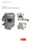
Transmitter
SITRANS P300
with PROFIBUS PA communication
pressure
measurement
Introduction
1
General safety instructions
2
Pressure transmitter
Description
3
Transmitter
SITRANS P300 with PROFIBUSPA communication
Installation
4
Connecting
5
Operation
6
Operating functions over
PROFIBUS
7
Configuration/projection
8
Commissioning
9
Operating Instructions
06/2005
A5E00414588-02
Error and system messages
10
Specifications
11
Dimension drawings
12
Appendix
A
List of
Abbreviations/Acronyms
B
Safety Guidelines
This manual contains notices you have to observe in order to ensure your personal safety, as well as to prevent
damage to property. The notices referring to your personal safety are highlighted in the manual by a safety alert
symbol, notices referring to property damage only have no safety alert symbol. These notices shown below are
graded according to the degree of danger.
Danger
indicates that death or severe personal injury will result if proper precautions are not taken.
Warning
indicates that death or severe personal injury may result if proper precautions are not taken.
Caution
with a safety alert symbol, indicates that minor personal injury can result if proper precautions are not taken.
Caution
without a safety alert symbol, indicates that property damage can result if proper precautions are not taken.
Notice
indicates that an unintended result or situation can occur if the corresponding information is not taken into
account.
If more than one degree of danger is present, the warning notice representing the highest degree of danger will
be used. A notice warning of injury to persons with a safety alert symbol may also include a warning relating to
property damage.
Qualified Personnel
The device/system may only be set up and used in conjunction with this documentation. Commissioning and
operation of a device/system may only be performed by qualified personnel. Within the context of the safety notes
in this documentation qualified persons are defined as persons who are authorized to commission, ground and
label devices, systems and circuits in accordance with established safety practices and standards.
Prescribed Usage
Note the following:
Warning
This device may only be used for the applications described in the catalog or the technical description and only in
connection with devices or components from other manufacturers which have been approved or recommended
by Siemens. Correct, reliable operation of the product requires proper transport, storage, positioning and
assembly as well as careful operation and maintenance.
Trademarks
All names identified by ® are registered trademarks of the Siemens AG. The remaining trademarks in this
publication may be trademarks whose use by third parties for their own purposes could violate the rights of the
owner.
Copyright Siemens AG 2005. All rights reserved.
The distribution and duplication of this document or the utilization and transmission of its
contents are not permitted without express written permission. Offenders will be liable for
damages. All rights, including rights created by patent grant or registration of a utility
model or design, are reserved.
Disclaimer of Liability
We have reviewed the contents of this publication to ensure consistency with the
hardware and software described. Since variance cannot be precluded entirely, we cannot
guarantee full consistency. However, the information in this publication is reviewed
regularly and any necessary corrections are included in subsequent editions.
Siemens AG
Automation and Drives
Postfach 4848, 90327 Nuremberg, Germany
Siemens AG 2005
Technical data subject to change
Siemens Aktiengesellschaft
A5E00414588-02
Table of contents
1
2
3
4
5
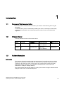
Introduction............................................................................................................................................. 1-1
1.1
Purpose of this documentation .................................................................................................. 1-1
1.2
Change history ........................................................................................................................... 1-1
1.3
Further information..................................................................................................................... 1-1
General safety instructions ..................................................................................................................... 2-1
2.1
General information ................................................................................................................... 2-1
2.2
Correct usage............................................................................................................................. 2-1
2.3
Laws and directives ................................................................................................................... 2-1
2.4
Measures ................................................................................................................................... 2-2
2.5
Qualified Personnel.................................................................................................................... 2-3
Description.............................................................................................................................................. 3-1
3.1
System configuration ................................................................................................................. 3-1
3.2
Applications................................................................................................................................ 3-2
3.3
Operation ................................................................................................................................... 3-3
3.4
Structure..................................................................................................................................... 3-3
3.5
Structure of the nameplate......................................................................................................... 3-4
3.6
3.6.1
3.6.2
3.6.3
Mode of operation ...................................................................................................................... 3-5
Overview of mode of operation .................................................................................................. 3-5
Operation of the electronics ....................................................................................................... 3-6
Measuring cell operation............................................................................................................ 3-7
3.7
SIMATIC PDM.......................................................................................................................... 3-11
3.8
3.8.1
3.8.2
3.8.3
3.8.4
PROFIBUS............................................................................................................................... 3-12
Overview .................................................................................................................................. 3-12
Transmission technology ......................................................................................................... 3-12
Topology .................................................................................................................................. 3-12
Properties of PROFIBUS PA ................................................................................................... 3-14
Installation .............................................................................................................................................. 4-1
4.1
Safety information for installation............................................................................................... 4-1
4.2
4.2.1
4.2.2
Installing gauge and absolute pressure versions....................................................................... 4-3
Information for installing gauge and absolute pressure versions .............................................. 4-3
Installation for gauge and absolute pressure............................................................................. 4-4
4.3
4.3.1
4.3.2
Installation for level version........................................................................................................ 4-4
Information for installing level version........................................................................................ 4-4
Installation for level .................................................................................................................... 4-6
Connecting ............................................................................................................................................. 5-1
SITRANS P300 with PROFIBUS-PA communication
Operating Instructions, 06/2005, A5E00414588-02
iii
Table of contents
6
7
iv
5.1
Connection safety information ................................................................................................... 5-1
5.2
Connecting the transmitter ......................................................................................................... 5-2
Operation................................................................................................................................................ 6-1
6.1
Overview of operation ................................................................................................................ 6-1
6.2
Safety information for operation................................................................................................. 6-2
6.3
Information on operation ............................................................................................................ 6-2
6.4
6.4.1
6.4.2
6.4.3
6.4.4
6.4.5
Digital display ............................................................................................................................. 6-3
Elements of the digital display ................................................................................................... 6-3
Units display............................................................................................................................... 6-4
Error display ............................................................................................................................... 6-4
Mode display .............................................................................................................................. 6-5
Status display............................................................................................................................. 6-6
6.5
6.5.1
6.5.2
6.5.3
6.5.4
6.5.5
6.5.6
6.5.7
6.5.8
6.5.9
6.5.10
6.5.11
6.5.12
6.5.13
6.5.14
Local operation........................................................................................................................... 6-6
Local control elements ............................................................................................................... 6-6
Operating via keys ..................................................................................................................... 6-8
Adjusting electrical damping .................................................................................................... 6-10
Zero point calibration................................................................................................................ 6-10
Locking keys ............................................................................................................................ 6-11
Releasing key or function lock ................................................................................................. 6-12
Source of measured value display........................................................................................... 6-13
Unit ........................................................................................................................................... 6-15
Bus address ............................................................................................................................. 6-18
Device operation type .............................................................................................................. 6-19
Position of the decimal point .................................................................................................... 6-21
Display of the zero-point adjustment........................................................................................ 6-22
LO calibration ........................................................................................................................... 6-22
HI calibration ............................................................................................................................ 6-24
Operating functions over PROFIBUS...................................................................................................... 7-1
7.1
7.1.1
7.1.2
7.1.3
7.1.3.1
7.1.3.2
7.1.3.3
7.1.4
7.1.5
7.1.6
Communication structure for PROFIBUS PA............................................................................. 7-1
Overview .................................................................................................................................... 7-1
Block model for collection and processing of measured values ................................................ 7-1
Pressure transducer block ......................................................................................................... 7-4
Pressure transducer block (transducer block 1) ........................................................................ 7-4
Linearization type function group ............................................................................................... 7-6
Units of the pressure transducer block ...................................................................................... 7-8
Electronics temperature transducer block.................................................................................. 7-8
Analog input function block ........................................................................................................ 7-9
Totalizer function block ............................................................................................................ 7-10
7.2
Overview of operating functions............................................................................................... 7-10
7.3
Measurement ........................................................................................................................... 7-10
7.4
7.4.1
7.4.2
7.4.3
7.4.4
7.4.5
7.4.6
Settings .................................................................................................................................... 7-11
Overview of settings................................................................................................................. 7-11
Settings .................................................................................................................................... 7-11
Pressure measurement............................................................................................................ 7-11
Fill level measurement ............................................................................................................. 7-12
Flow measurement................................................................................................................... 7-15
Adjusting to a desired process value ....................................................................................... 7-15
7.5
Electrical damping.................................................................................................................... 7-17
7.6
Key lock and write protection ................................................................................................... 7-17
SITRANS P300 with PROFIBUS-PA communication
Operating Instructions, 06/2005, A5E00414588-02
Table of contents
8
9
10
7.7
Warning and alarm limits ......................................................................................................... 7-18
7.8
7.8.1
7.8.2
Failure behavior ....................................................................................................................... 7-20
Overview of failure behavior .................................................................................................... 7-20
Output ...................................................................................................................................... 7-20
7.9
7.9.1
7.9.2
7.9.3
7.9.4
7.9.5
Diagnostic functions................................................................................................................. 7-20
Operating hours counter .......................................................................................................... 7-20
Calibration interval and service interval ................................................................................... 7-20
Clearing warning ...................................................................................................................... 7-21
Clearing the alarm.................................................................................................................... 7-22
Min/max pointer........................................................................................................................ 7-22
7.10
7.10.1
7.10.2
7.10.3
7.10.4
7.10.5
Simulation ................................................................................................................................ 7-23
Overview of simulation............................................................................................................. 7-23
Simulating output ..................................................................................................................... 7-24
Simulating input ....................................................................................................................... 7-24
Simulating the pressure sensor ............................................................................................... 7-24
Simulating sensor and electronics temperature....................................................................... 7-26
7.11
Calibrating the sensor .............................................................................................................. 7-26
7.12
Correcting for positional error .................................................................................................. 7-27
7.13
7.13.1
7.13.2
7.13.3
Resetting .................................................................................................................................. 7-28
Resetting to delivery state........................................................................................................ 7-28
Warm start/restart .................................................................................................................... 7-28
Resetting the PROFIBUS address .......................................................................................... 7-28
Configuration/projection.......................................................................................................................... 8-1
8.1
Cyclical data transfer ................................................................................................................. 8-1
8.2
8.2.1
8.2.2
8.2.3
8.2.4
8.2.5
Configuration.............................................................................................................................. 8-1
Overview of configuration .......................................................................................................... 8-1
Configuration of user data.......................................................................................................... 8-2
Transmission of user data over PROFIBUS .............................................................................. 8-3
Status ......................................................................................................................................... 8-4
Diagnosis ................................................................................................................................... 8-4
8.3
Acyclic data transfer................................................................................................................... 8-6
Commissioning ....................................................................................................................................... 9-1
9.1
Safety instructions for commissioning ....................................................................................... 9-1
9.2
Instructions for commissioning................................................................................................... 9-2
9.3
Introduction to commissioning ................................................................................................... 9-3
9.4
Commissioning with steam or liquid .......................................................................................... 9-3
9.5
Commissioning for gases........................................................................................................... 9-5
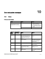
Error and system messages ................................................................................................................. 10-1
10.1
11
12
Errors ....................................................................................................................................... 10-1
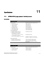
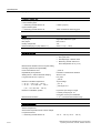
Specifications ....................................................................................................................................... 11-1
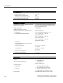
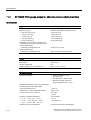
11.1
SITRANS P300 gauge pressure / absolute pressure .............................................................. 11-1
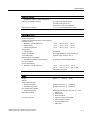
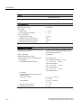
11.2
SITRANS P300 gauge pressure / absolute pressure (flush-mounted).................................... 11-6
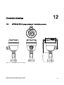
Dimension drawings ............................................................................................................................. 12-1
12.1
SITRANS P300 gauge pressure / absolute pressure .............................................................. 12-1
SITRANS P300 with PROFIBUS-PA communication
Operating Instructions, 06/2005, A5E00414588-02
v
Table of contents
A
B
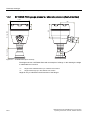
12.2
SITRANS P300 gauge pressure / absolute pressure (flush-mounted).................................... 12-2
12.3
Flanges as per EN and ASME ................................................................................................. 12-3
12.4
F&B and pharma flange ........................................................................................................... 12-4
12.5
Bioconnect/Biocontrol .............................................................................................................. 12-5
12.6
PMC Style ................................................................................................................................ 12-7
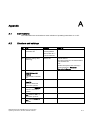
Appendix.................................................................................................................................................A-1
A.1
Certifications ..............................................................................................................................A-1
A.2
Literature and catalogs...............................................................................................................A-1
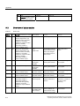
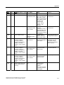
A.3
Overview of status codes ...........................................................................................................A-2
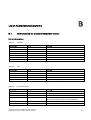
List of Abbreviations/Acronyms...............................................................................................................B-1
B.1
Abbreviations for pressure transmitter overall ...........................................................................B-1
Glossary ..................................................................................................................................... Glossary-1
Index
Tables
Table 6-1
Operating functions .................................................................................................................... 6-2
Table 6-2
Meaning of the arrow displays ................................................................................................... 6-6
Table 6-3
Operating functions via keys ...................................................................................................... 6-7
Table 6-4
Meaning of the lock modes ...................................................................................................... 6-12
Table 6-5
Measurement type "Pressure" ................................................................................................. 6-13
Table 6-6
Measurement type "Level" ....................................................................................................... 6-14
Table 6-7
Measurement type "Volume".................................................................................................... 6-14
Table 6-8
Unit for pressure (P)................................................................................................................. 6-16
Table 6-9
Unit for volume (V) ................................................................................................................... 6-16
Table 6-10
Unit for level (L)........................................................................................................................ 6-17
Table 6-11
Unit for mass (M)...................................................................................................................... 6-17
Table 6-12
Unit for temperature (T)............................................................................................................ 6-17
Table 6-13
Unit for user-specific (U) .......................................................................................................... 6-18
Table 6-14
Device operation type .............................................................................................................. 6-19
Table 6-15
Device master data file............................................................................................................. 6-20
Table 7-1
Connection between blocks ....................................................................................................... 7-3
Table 7-2
Display on digital display............................................................................................................ 7-4
Table 7-3
Available linearization functions................................................................................................. 7-7
Table 7-4
Overview of available units ........................................................................................................ 7-8
Table 7-5
Keypad locks............................................................................................................................ 7-17
Table 7-6
Combined blocks...................................................................................................................... 7-18
Table 7-7
Limits and status displays ........................................................................................................ 7-18
vi
SITRANS P300 with PROFIBUS-PA communication
Operating Instructions, 06/2005, A5E00414588-02
Table of contents
Table 7-8
Failure behavior of the analog input function block ................................................................. 7-20
Table 8-1
User data dependent on the selected function block................................................................. 8-2
Table 8-2
User data, dependent on selected additional function in the totalizer output function block..... 8-3
Table 8-3
IEEE standard floating point representation of the measured value ......................................... 8-3
Table 8-4
Example status code.................................................................................................................. 8-4
Table 8-5
Diagnostic messages................................................................................................................. 8-5
Table 10-1
Error message.......................................................................................................................... 10-1
Table A-1
Status code ................................................................................................................................ A-2
Table B-1
Variables .................................................................................................................................... B-1
Table B-2
Units ........................................................................................................................................... B-1
Table B-3
Other abbreviations.................................................................................................................... B-1
SITRANS P300 with PROFIBUS-PA communication
Operating Instructions, 06/2005, A5E00414588-02
vii
Table of contents
viii
SITRANS P300 with PROFIBUS-PA communication
Operating Instructions, 06/2005, A5E00414588-02
1
Introduction
1.1
Purpose of this documentation
These instructions contain all the information you need for commissioning and using the
transmitter.
It is aimed both at persons mechanically installing the device, connecting it electronically,
configuring the parameters and commissioning it as well as service and maintenance
engineers.
1.2
Change history
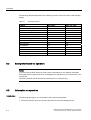
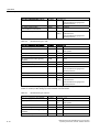
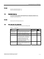
Currently released versions of these instructions:
Edition
Comment
Firmware identifier, System integration
nameplate
Installation path for
PDM
05/2005
First edition
FW: 0300.01.08
SITRANS P300
PDM V 6.00;
Dev. R.1 DD Rev.1
06/2005
02
FW: 0300.01.08
PDM V 6.00;
SITRANS P300
Dev. R.1 DD Rev.1
1.3
Further information
Information
The contents of these instructions shall not become part of or modify any prior or existing
agreement, commitment or relationship. All commitments on the part of Siemens AG are
contained in the respective sales contract which also contains the complete and solely
applicable warranty conditions. Any statements contained herein do not create new
warranties or modify the existing warranty.
The content reflects the technical status for printing. We reserve the right to make technical
changes in the course of further development.
SITRANS P300 with PROFIBUS-PA communication
Operating Instructions, 06/2005, A5E00414588-02
1-1
Introduction
1.3 Further information
References
If there are references to further information on an aspect described here, these will always
be found at the end of a chapter under "See also".
Offices
If you need more information or have particular problems which are not covered sufficiently
by the operating instructions, contact your local Siemens office. You will find your local
Siemens office on the Internet under:
www.siemens.de/prozessinstrumentierung
Click on "Contact" and select your closest town.
Product information on the Internet
The operating instructions are a constituent part of the enclosed CD "sitrans p
TRANSMITTERS" (order number A5E00090345) and is available on the Internet at:
www.siemens.de/sitransp
Click on "More Info" and "-> Operating instructions and manuals".
On the enclosed CD, you will find an extract of the catalog FI 01 "Field devices for process
automation" with the current order data. The entire FI 01 catalog is also available at the
above Web address.
1-2
SITRANS P300 with PROFIBUS-PA communication
Operating Instructions, 06/2005, A5E00414588-02
General safety instructions
2.1
2
General information
This device left the factory free from safety problems. In order to maintain this status and to
ensure safe operation of the device, please observe the safety information and warnings
contained in these instructions.
2.2
Correct usage
The device may only be used for the purposes specified in these instructions.
Insofar as they are not expressly stated in these instructions, all changes to the device are
the sole responsibility of the user.
2.3
Laws and directives
The regulations of the test certification valid in your country are to be observed.
Electrical connection in hazardous zones with explosive atmospheres
The national directives and laws for hazardous areas valid in your country must be observed
for electrical connection. For example, in Germany these are:
• Operational safety regulations
• Directive for the installation of electrical systems in hazardous areas DIN EN 60079-14
(previously VDE 0165, T1)
SITRANS P300 with PROFIBUS-PA communication
Operating Instructions, 06/2005, A5E00414588-02
2-1
General safety instructions
2.4 Measures
2.4
Measures
For the sake of safety, the following precautions must be observed:
Warning
Type of protection "pressure-proof encapsulation"
Devices with "pressure-proof encapsulation" protection may only be opened when off circuit.
"Intrinsically safe" protection type
"Intrinsically-safe" devices lose their certification as soon as they are operated on circuits
which do not correspond with the test certification valid in their country.
Protection type "limited energy" nL (zone 2)
Devices with "limited energy" may be connected and disconnected while in operation.
Protection type "non-sparking" nA (zone 2)
Devices with "non-sparking" protection may only be connected and disconnected when off
circuit.
Warning
Exposure to aggressive and hazardous media
The device can be operated both at high pressure and with aggressive and hazardous
media. Therefore, improper use of this device may lead to serious injury and or considerable
damage to property. Above all, it must be noted when the device was in use and is to be
exchanged.
Caution
Electrostatic Sensitive Devices (ESD)
This device contains electrostatic sensitive devices. Electrostatic sensitive devices may be
destroyed by voltages that are undetectable to a human. Voltages of this kind occur as soon
as a component or an assembly is touched by a person who is not grounded against static
electricity. The damage to a module as a result of overvoltage cannot usually be detected
immediately. It may only become apparent after a long period of operation.
2-2
SITRANS P300 with PROFIBUS-PA communication
Operating Instructions, 06/2005, A5E00414588-02
General safety instructions
2.5 Qualified Personnel
2.5
Qualified Personnel
"Qualified personnel" means those who are familiar with the installation, mounting,
commissioning and operation of the product. They must have the following, appropriate
qualifications for their activities:
• Training or instruction/authorization in operating and maintaining devices and systems
according to the safety regulations for electrical circuits, high pressures and aggressive
as well as hazardous media.
• For explosion-proof devices: Training or instruction/authorization in carrying out work on
electrical circuits for hazardous systems.
• Training and instruction in maintenance and use of adequate safety equipment according
to safety regulations.
• Should be trained in first aid.
SITRANS P300 with PROFIBUS-PA communication
Operating Instructions, 06/2005, A5E00414588-02
2-3
General safety instructions
2.5 Qualified Personnel
2-4
SITRANS P300 with PROFIBUS-PA communication
Operating Instructions, 06/2005, A5E00414588-02
Description
3.1
3
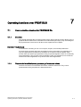
System configuration
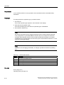
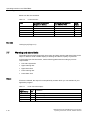
Overview
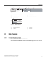
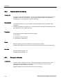
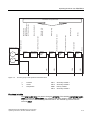
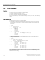
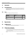
The pressure transmitter can be used in a number of system configurations:
We recommend use as a part of a complex system environment, e.g. SIMATIC S7.
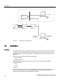
System communication
Communication is via the PROFIBUS-PA protocol, using:
• SIMATIC PDM
• Control system communicating over the PROFIBUS, e.g. SIMATIC S7
SITRANS P300 with PROFIBUS-PA communication
Operating Instructions, 06/2005, A5E00414588-02
3-1
Description
3.2 Applications
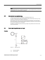
6,0$7,&3'0
66
&RQWUROV\VWHP
-
'3
'3
7UDQVPLWWHU
&RXSOHU
.
'3
3$
+
/LQN
352),%86
&RPPXQLFDWLRQ
3URFHVVRU&3
Figure 3-1
3.2
3&/DSWRSZLWK
6,0$7,&3'0
Possible system configurations
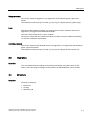
Applications
Overview
The pressure transmitter is available in the gauge pressure and absolute pressure versions.
The output signal is a PROFIBUS-PA signal linearly proportional to the input pressure. The
pressure transmitter measures aggressive, non-aggressive and hazardous gases, vapors
and liquids.
It can be used for the following measurement types:
• Gauge pressure
• Absolute pressure
With appropriate parameter settings, it can also be used for the following additional
measurement types:
• Level
• Volume
• Mass
The "intrinsically-safe" EEx version of the transmitter can be installed in hazardous areas
(zone 1). The devices have an EC type examination certificate and comply with the
appropriate harmonized European CENELEC standards .
3-2
SITRANS P300 with PROFIBUS-PA communication
Operating Instructions, 06/2005, A5E00414588-02
Description
3.3 Operation
Gauge pressure
This version measures aggressive, non-aggressive and hazardous gases, vapors and
liquids.
The smallest measuring range is 8 mbar g (0.12 psi g), the largest 400 bar g (5802 psi g).
Level
With appropriate parameter settings, the gauge pressure version measures the level of
aggressive, non-aggressive and hazardous liquids.
The level can be measured in an open container.
The parts in contact with the measured medium are made of various materials, depending
on corrosion resistance requirements.
Absolute pressure
This version measures the absolute pressure of aggressive, non-aggressive and hazardous
gases, vapors and liquids.
The smallest measuring range is 8 mbar a (0.12 psi a), the largest 30 bar a (435 psi a).
3.3
Operation
Overview
You can operate the basic settings of the pressure transmitter using the buttons on the
device. The entire range of settings can be operated via PROFIBUS-PA communication.
3.4
Structure
Overview
The device comprises:
• Electronics
• Housing
• Measuring cell
SITRANS P300 with PROFIBUS-PA communication
Operating Instructions, 06/2005, A5E00414588-02
3-3
Description
3.5 Structure of the nameplate
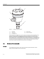
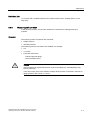
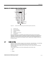
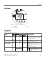
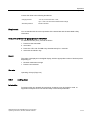
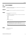
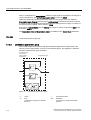
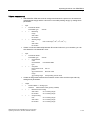
Figure 3-2
Perspective view of the P300
(1)
Nameplate
(4)
Digital display
(2)
Cable gland
(5)
Process connection
(3)
Screwable cover
The housing has a screwable cover, with or without an inspection window depending on the
version. The electrical cable compartment, the buttons for operation of the device and,
depending on the version, the digital display are located under this cover. The connections
for the auxiliary power UH and the shield are in the cable compartment. The cable gland is on
the side of the housing. The measuring cell with the process connection (5) is located on the
underside of the housing. Depending on the version of the device, the measuring cell with
the process connection may differ from the one shown in the diagram.
3.5
Structure of the nameplate
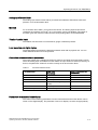
Overview
The nameplate which bears the order number and other important information such as
design or technical details is found on the housing.
3-4
SITRANS P300 with PROFIBUS-PA communication
Operating Instructions, 06/2005, A5E00414588-02
Description
3.6 Mode of operation
,3 ' .DUOVUXKH
6,75$163
0DGH LQ )UDQFH
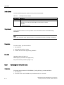
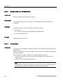
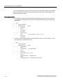
Figure 3-3
3('6(3
0)%$%$=
): +: )1U
Nameplate
(1)
Product name/manufacturer
(4)
Serial number
(2)
Product information
(5)
Certification information
(3)
Specifications
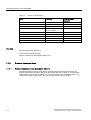
,3 3('6(3
0)%$%$=
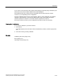
): +: Figure 3-4
Product information
(1)
Degree of protection
(3)
Firmware
(2)
Order no.
(4)
Hardware
3.6
Mode of operation
3.6.1
Overview of mode of operation
This chapter describes how the transmitter works.
First the electronics are described, then the physical principle of the sensors which are used
with the various device versions for the individual measurement types.
SITRANS P300 with PROFIBUS-PA communication
Operating Instructions, 06/2005, A5E00414588-02
3-5
Description
3.6 Mode of operation
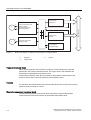
3.6.2
Operation of the electronics
Description
3$LQWHUIDFH 352),
%863$
((3520
&HOO
6HQVRU
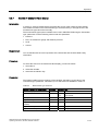
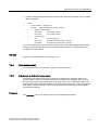
Figure 3-5
((3520
(OHFWU
$X[LOLDU\SRZHU
3RZHU
VXSSO\
352),%86'3
&RXS
OHU
%XV
PDVWHU
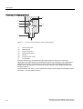
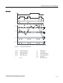
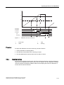
Operation of the electronics with PROFIBUS-PA communication
(1)
Measuring cell sensor
(2)
Measuring amplifier
(3)
Analog-to-digital converter
(4)
Microcontroller
(5)
Voltage isolation
(6)
Each with a non-volatile memory in the measuring cell and in the electronics
(7)
PROFIBUS-PA interface
(8)
Buttons (local operation)
(9)
Digital display
(10)
Auxiliary power source
(11)
DP/PA coupler or link
(12)
Bus master
The input pressure is converted into an electrical signal by the sensor (1). This signal is
amplified by the measuring amplifier (2) and digitized in an analog to digital converter (3).
The digital signal is analyzed in a microcontroller (4) and corrected with regard to linearity
and thermal characteristics. It is then made available on the PROFIBUS PA via a voltageisolated PROFIBUS-PA interface (7). The data specific to the measuring cell, the electronic
data and parameter settings are stored in two non-volatile memories (6). The first memory is
linked with the measuring cell, the second with the electronics.
The buttons (8) can be used to call up individual functions, so-called modes. You can track
the mode settings and other device messages. The basic mode settings can be changed
with a computer via the bus master (12).
Definition: Coupler
in PROFIBUS, connects the DP and PA segments. It has a fixed baud rate. The baud rate is
45.45 kbps (DP) to 31.25 kbps (PA).
3-6
SITRANS P300 with PROFIBUS-PA communication
Operating Instructions, 06/2005, A5E00414588-02
Description
3.6 Mode of operation
Definition: Link
is a coupler with a variable baudrate. The maximum baud rate is 12 Mbps (DP) to 31.25
kbps (PA).
3.6.3
Measuring cell operation
In the following sections, the process variable to be measured is called general input
pressure.
Overview
The following modes of operation are described:
• Gauge pressure
• Absolute pressure
The following process connections are available, for example:
• G½
• ½-14 NPT
• Front-flush membrane:
– F&B and pharma flange
– Bioconnect/Biocontrol
Caution
If the measurement signal fails because of sensor breakage, the seal diaphragm may
also be destroyed.
In the worst case, the process medium escapes at the process connection in devices for
gauge pressure with a span of ≤ 63 bar.
SITRANS P300 with PROFIBUS-PA communication
Operating Instructions, 06/2005, A5E00414588-02
3-7
Description
3.6 Mode of operation
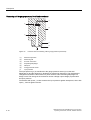
Measuring cell for gauge pressure
3H
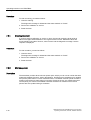
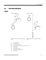
Figure 3-6
Function chart of measuring cell for gauge pressure
(1)
Reference pressure
(2)
Measuring cell
(3)
Process connection
(4)
Separating diaphragm
(5)
Fill liquid
(6)
Gauge pressure sensor
pe
Input pressure
The input pressure (pe) is transferred to the gauge pressure sensor (6) via the seal
diaphragm (4) and the fill liquid (5), displacing its measuring diaphragm. The displacement
changes the resistance value of the four piezo resistors in the measuring diaphragm in a
bridge circuit. The change in the resistance causes a bridge output voltage proportional to
the input pressure.
The transmitters with spans ≤ 63 bar measure the input pressure against atmosphere, those
with spans ≥ 160 bar against vacuum.
3-8
SITRANS P300 with PROFIBUS-PA communication
Operating Instructions, 06/2005, A5E00414588-02
Description
3.6 Mode of operation
Measuring cell for absolute pressure
(1)
(5)
(4)
(3)
(2)
SH
Figure 3-7
(1)
Function chart of measuring cell for absolute pressure
Measuring cell
(2)
Process connection
(3)
Separating diaphragm
(4)
Fill liquid
(5)
Absolute pressure sensor
pe
Input pressure
The input pressure (pe) is transferred to the absolute pressure sensor (6) via the seal
diaphragm (3) and the fill liquid (4), displacing its measuring diaphragm. The displacement
changes the resistance value of the four piezo resistors in the measuring diaphragm in a
bridge circuit. The change in the resistance causes a bridge output voltage proportional to
the input pressure.
SITRANS P300 with PROFIBUS-PA communication
Operating Instructions, 06/2005, A5E00414588-02
3-9
Description
3.6 Mode of operation
Measuring cell for gauge pressure, front-flush membrane
SH
Figure 3-8
Function chart of measuring cell for gauge pressure (front-flush)
(1)
Reference pressure
(2)
Measuring cell
(3)
Process connection
(4)
Separating diaphragm
(5)
Fill liquid
(6)
Gauge pressure sensor
pe
Input pressure
The input pressure (pe) is transferred to the gauge pressure sensor (6) via the seal
diaphragm (4) and the fill liquid (5), displacing its measuring diaphragm. The displacement
changes the resistance value of the four piezo resistors in the measuring diaphragm in a
bridge circuit. The change in the resistance causes a bridge output voltage proportional to
the input pressure.
Transmitters with spans ≤ 63 bar measure the input pressure against atmosphere, those with
spans ≥ 160 bar against vacuum.
3-10
SITRANS P300 with PROFIBUS-PA communication
Operating Instructions, 06/2005, A5E00414588-02
Description
3.7 SIMATIC PDM
Measuring cell for absolute pressure, front-flush membrane
SH
Figure 3-9
Function chart of measuring cell for absolute pressure (front-flush)
(1)
Measuring cell
(2)
Process connection
(3)
Separating diaphragm
(4)
Fill liquid
(5)
Absolute pressure sensor
pe
Input pressure
The input pressure (pe) is transferred to the absolute pressure sensor (6) via the seal
diaphragm (3) and the fill liquid (4), displacing its measuring diaphragm. The displacement
changes the resistance value of the four piezo resistors in the measuring diaphragm in a
bridge circuit. The change in the resistance causes a bridge output voltage proportional to
the input pressure.
3.7
SIMATIC PDM
SIMATIC PDM is a software package for the configuration, paramaterization, commissioning,
diagnosis, and servicing of the SITRANS P300 and other process equipment.
SIMATIC PDM includes simple process monitoring of process values, alarms, and device
status information.
Using SIMATIC PDM, you can do the following with process device data:
• display
• set
• change
SITRANS P300 with PROFIBUS-PA communication
Operating Instructions, 06/2005, A5E00414588-02
3-11
Description
3.8 PROFIBUS
• compare
• check for plausibility
• administer
• simulate
3.8
PROFIBUS
3.8.1
Overview
The Process Field Bus (PROFIBUS) is an open communication system for automation
technology and is specified in the European standard EN 50170.
PROFIBUS Process Automation (PROFIBUS PA) is a variant of PROFIBUS Decentral
Peripherals (PROFIBUS DP), which is widely used in process technology.
3.8.2
Transmission technology
PROFIBUS PA uses a special transmission technology, enabling it to fulfill the requirements
of process automation and process technology. This transmission technology is defined in
the international standard IEC 61158-2. The low transmission rate reduces the power loss in
comparison to PROFIBUS DP, enabling an intrinsically safe technology for use in hazardous
zones with explosive atmospheres.
3.8.3
Topology
The bus topology can be largely freely selected, so that line, star, and tree structures, as well
as mixed forms, are possible. All types of field devices such as sensors, actors, analysis
devices, etc. can be connected to the PROFIBUS PA.
Advantages include:
• Savings on installation costs
• More extensive diagnostics, leading to increased availability of installation sections
• Automatic management of installation documentation
• Installation optimization on the fly during operation
In an automation system, there are in general multiple PROFIBUS-PA strands connected to
the fast PROFIBUS DP via coupler units. This is also connected to the process control
system.
Both bus systems use the same protocol layer. This makes PROFIBUS PA a
"communications-compatible" extension of the PROFIBUS DP into the field.
3-12
SITRANS P300 with PROFIBUS-PA communication
Operating Instructions, 06/2005, A5E00414588-02
Description
3.8 PROFIBUS
Class 1 master
Class 2 master
(Class 1)
PROFIBUS DP
PROFIBUS PA
6ODYHV
Field devices, decentralized peripherals, subordinate
controllers, gateway to PROFIBUS-PA
Figure 3-10
Functional principle of the PROFIBUS automation system
The figure shows a section of a typical PROFIBUS automation system. The control system
consists of two masters with distributed tasks.
The class-1 master performs control and regulation tasks, while the class-2 master enables
operation and observation functions. Between the class-1 master and the field devices there
is a periodic exchange of measurement and settings data. The status information from the
field devices is transmitted parallel to this data, and evaluated in the class-1 master.
Parameterization of the field devices or the readout of additional device information is not
performed during periodic operation.
Besides periodic operation, one or more class-2 masters can access the field devices
asynchronously. Using this type of communication, additional information can be retrieved
from the devices or settings sent to them.
Definition: Device master data
The control system finds the information necessary for establishing communications in the
device master data (DMD).
Reference
http://www.ad.siemens.de/csi_e/gsd
SITRANS P300 with PROFIBUS-PA communication
Operating Instructions, 06/2005, A5E00414588-02
3-13
Description
3.8 PROFIBUS
3.8.4
Properties of PROFIBUS PA
Properties
PROFIBUS PA enables the bidirectional communication of a bus master with field devices.
At the same time, the shielded two-strand wiring provides auxiliary power to the two-wire
field devices.
Profile
As an extension to the EN 50170 standard, the PROFIBUS user organization (PNO) defined
the functionality of the individual field device types in a so-called profile description. This
profile determines minimum functional requirements and optional extensions. The deviceinternal "Device Management" provides the configuration tool of the control system with all
necessary basic information to find profile parameters. One parameterization tool serves all
profile-conforming devices, regardless of type or manufacturer.
Depending on the size of the installation (and therefore the number of field devices) and the
time behavior required, you implement the system with one or more PROFIBUS PA strands.
One PROFIBUS PA strand consists of the components shown in the following figure.
&RQWUROURRP
$UUD\
352),%86'3
&RXSOHU
3&6
3&
352),%863$
7
7
)*
)*
3RZHU
VXSSO\
Figure 3-11
$GGLWLRQDO
OLQHWHUPLQDWRU
PROFIBUS PA strand
FG
Field device
PC
Personal Computer
T
Terminating resistor
PCS
Process control system
Connection
Control is performed by the central process control system (PCS), or by a PC for lowerperformance requirements.
In general, the following functions are combined into one coupling assembly:
• DP/PA signal transfer
3-14
SITRANS P300 with PROFIBUS-PA communication
Operating Instructions, 06/2005, A5E00414588-02
Description
3.8 PROFIBUS
• Bus power
• Bus termination
Depending on the number of the PROFIBUS PA field devices to be operated in the
automation system and the time behavior required, a DP/PA coupler or a DP/PA link is used.
For standard requirements, you use a DP/PA coupler; for higher requirements, a more
powerful DP/PA link.
For reasons related to transmission technology, the bus is also equipped on the far end with
a terminating resistance T. When using the recommended bus cable, the theoretical
maximum cable length is 1900 meters. The theoretical maximum cable length is the sum of
all cable segments. During planning, also take into account the voltage drop over the wires
powering the field devices.
However, the power requirements of the individual nodes and the voltage drop on the cable
must also be calculated during projection. The individual field devices (FD) can be connected
at nearly any point in the bus system.
DP/PA couplers or DP/PA links are supplied using a safety extra-low voltage (SELV) power
supply. This power supply must have sufficient reserves to bridge over temporary power
failures.
The maximum number of devices which can be connected to one bus strand depends on
their power consumption and the conditions of use. When operated in the safe zone, the
couplers or links supply the bus with up to 400 mA.
When operated in explosive atmospheres, intrinsic safety is only guaranteed if all devices,
components, etc. connected to the bus (e.g. bus terminator) fulfill the following requirements:
• They are certified as intrinsically safe equipment.
• They fulfill the requirements of the FISCO model (Fieldbus Intrinsic Safety Concept).
Power supply devices in particular (bus couplers) must be certified as so-called FISCO
power supplies. Observe the safety-relevant maximum values and other specifications of the
EG type test certificate.
Connect power supplies (bus couplers) which are not explosion protected and certified to
intermediate EX-certified zener barriers. Observe the specifications of the EG type test
certificate.
Warning
For power supply to intrinsically safe PROFIBUS, use only power supplies, DP/PA couplers,
or DP/PA links certified as compliant with the FISCO model.
Switch through zener barriers if using non-EX-protected power supplies. See the
requirements of the EG type test certificate.
The number of devices which can be connected to a bus strand can be calculated from the
sum of the maximum power consumption of the devices and the power available. By default,
assume 10 mA per device. For safety reasons, plan for a power reserve. Otherwise you run
the risk of a defective device overloading the bus with an increased power consumption. This
can interrupt the power supply and communication with the functioning nodes. The amount
of power reserved is based on the nominal power increase given by the manufacturer in
case of failure.
SITRANS P300 with PROFIBUS-PA communication
Operating Instructions, 06/2005, A5E00414588-02
3-15
Description
3.8 PROFIBUS
So that the connected process devices can be distinguished from one another, each device
has its own address.
Reference
PNO PROFIBUS-PA interest group
See also
Literature and catalogs (Page A-1)
3-16
SITRANS P300 with PROFIBUS-PA communication
Operating Instructions, 06/2005, A5E00414588-02
Installation
4.1
4
Safety information for installation
Requirement
The SITRANS P300 transmitter can be installed in different application areas.
Depending on the area of application and the system configuration, there may be differences
in the installation.
Warning
Protection against incorrect use of the measuring device
Take particular care to ensure that the selected materials for the wetted parts are suitable for
the process media used.
Ignoring this safety measure may cause bodily and life-threatening injury and damage the
environment.
Caution
Contact protection is required for surface temperatures > 70 °C.
The shock protection must be designed in such a way that, if there is a buildup of heat, the
maximum permitted ambient temperature at the device is not exceeded.
The permissible ambient temperature can be found in the specifications.
Caution
The device may only be used within the measuring range, overload pressure limits and
voltage limits dependent on the protection type specified on the nameplate.
SITRANS P300 with PROFIBUS-PA communication
Operating Instructions, 06/2005, A5E00414588-02
4-1
Installation
4.1 Safety information for installation
Notice
External loads may not be allowed to affect the transmitter as this may result in an incorrect
measured value or even destruction of the device. In the worst case scenario, the process
medium will escape.
Warning
"Intrinsically-safe" protection type
Information for operating the intrinsically-safe version in hazardous areas:
Operation is only permissible in certified intrinsically-safe circuits. The transmitter
corresponds to category 1/2 and may be installed in Zone 0.
The EC type examination certificate applies to installation of the device in the walls of
containers and pipes in which explosive gas/air or vapor/air mixtures occur only under
atmospheric conditions (Pressure: 0.8 bar to 1.1 bar; Temperature: -20 °C to +60 °C). The
permitted range of the ambient temperature is to be found in the specifications or, for
explosion-proof devices, in the EC type examination certificate.
The operator may use the device under non-atmospheric conditions outside the limits
specified in the EC type examination certificate (or the certification applicable in the country
of use) at the operator's own risk if safety measures which may be necessary in accordance
with use conditions (explosive mixture) have been taken. The limit values specified in the
general specifications are to be complied with in all cases.
Additional information for zone 0
Additional requirements apply for installation in zone 0:
The installation must be sufficiently tight (IP67 according to EN 60 529). For instance, an
industry standard (e.g. DIN, NPT) threaded connector is suitable.
When operating with intrinsically safe power supplies in category "EEX ia", explosion safety
does not depend on the chemical stability of the isolation membrane.
When operating in Zone 0 with intrinsically safe power supplies in category "EEx ib", a
regular leakage test must be performed to test the seal of the isolation membrane of the
transmitter. Under these operating conditions, the transmitter may only be used for such
combustible gases and liquids for which the seal diaphragm is sufficiently resistant to
chemicals and corrosion.
4-2
SITRANS P300 with PROFIBUS-PA communication
Operating Instructions, 06/2005, A5E00414588-02
Installation
4.2 Installing gauge and absolute pressure versions
4.2
Installing gauge and absolute pressure versions
4.2.1
Information for installing gauge and absolute pressure versions
Requirements
The installation location is to be as follows:
• Easily accessible
• As close as possible to the measuring point
• Vibration-free
• Within the permitted ambient temperature values
Note
Protect the transmitter against:
•
•
•
•
Direct heat radiation
Rapid temperature fluctuations
Heavy contamination
Mechanical damage
Notice
Compare the desired operating data with the data on the nameplate.
Notice
The housing may only be opened for maintenance, local operation or to make electrical
connections.
Installation configuration
The transmitter may in principle be configured above or below the pressure tapping point.
The recommended configuration depends on the medium.
Installation configuration for gases
Install the transmitter above the pressure tapping point.
SITRANS P300 with PROFIBUS-PA communication
Operating Instructions, 06/2005, A5E00414588-02
4-3
Installation
4.3 Installation for level version
Lay the pressure tubing with a constant gradient to the pressure tapping point, so that any
condensate produced can drain in the main line and thereby avoid corruption of the
measured values.
Installation configuration for vapor and liquid
Install the transmitter below the pressure tapping point.
Lay the pressure tubing with a constant gradient to the pressure tapping point so that any
gas pockets can escape in the main line.
4.2.2
Installation for gauge and absolute pressure
Notice
When installing the process connection of the pressure transmitter, do not turn it on the
housing.
Procedure
To install the transmitter for pressure or absolute pressure, proceed as follows:
Attach the transmitter to the process connection with an appropriate tool.
4.3
Installation for level version
4.3.1
Information for installing level version
Requirement
The installation location is to be as follows:
• Easily accessible
• As close as possible to the measuring point
• Vibration-free
• Within the permitted ambient temperature values
4-4
SITRANS P300 with PROFIBUS-PA communication
Operating Instructions, 06/2005, A5E00414588-02
Installation
4.3 Installation for level version
Note
Protect the transmitter against:
•
•
•
•
Direct heat radiation
Rapid temperature fluctuations
Heavy contamination
Mechanical damage
Notice
Compare the desired operating data with the data on the nameplate.
Notice
The housing may only be opened for maintenance, local operation or to make electrical
connections.
Installation configuration
The transmitter can only be used in non-pressurized vessels for level.
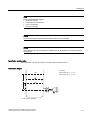
Installation height
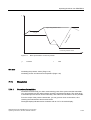
Formula:
Zero point: pMA = ρ · g · HU
0(
Zero point: pME = ρ · g · HO
S
KR
0$
KX
Level of open container
SITRANS P300 with PROFIBUS-PA communication
Operating Instructions, 06/2005, A5E00414588-02
4-5
Installation
4.3 Installation for level version
MA
Zero point
ΔpMA
Limit point to be adjusted
ME
Limit point
ΔpME
Limit point to be adjusted
p
Pressure
ρ
Density of the measured medium in the
container
hU
Zero point
g
Local gravitational acceleration
hO
Limit point
Note
Select the height of the container flange for recording of the transmitter (measuring point)
such that the lowest level to be measured is always over the flange or at its upper edge.
4.3.2
Installation for level
Note
Seals are required for the installation.
Seals are not included in the delivery.
Procedure
To install the transmitter for level, proceed as follows:
1. Attach the seal to the container's mating flange.
Ensure that the seal is centrically positioned and that it does not restrict the movement of
the flange's seal diaphragm in any way as otherwise the tightness of the process
connection is not guaranteed.
2. Screw on the transmitter's flange.
3. Observe the installation position.
4-6
SITRANS P300 with PROFIBUS-PA communication
Operating Instructions, 06/2005, A5E00414588-02
5
Connecting
5.1
Connection safety information
Requirement
Warning
Fixed installation
Devices to be operated in hazardous areas should be connected with fixed cable installation.
This is not necessary for intrinsically safe devices or devices with ignition protection class
"nL" – "limited energy".
Warning
Tightness
Use cable with a diameter of 7 to 12 mm for protection class IP65 through IP68.
Warning
Observe the provisions of the test certification valid for your country.
Electrical connection in hazardous areas with explosive atmospheres
The national directives and laws for hazardous areas valid in your country must be observed
for electrical connection.
In Germany these are, for example:
•
•
Operational safety regulations
Directive for the installation of electrical systems in hazardous areas DIN EN 60079-14 (previously
VDE 0165, T1)
If auxiliary power is required, check that it corresponds with that on the nameplate and with
the test certification valid for your country.
SITRANS P300 with PROFIBUS-PA communication
Operating Instructions, 06/2005, A5E00414588-02
5-1
Connecting
5.2 Connecting the transmitter
Note
To improve the reliability:
•
•
•
•
5.2
Install the signal cable separately from cables with voltages > 60 V.
Use cable with twisted strands.
Stay away from large electrical systems.
Use shielded cable to guarantee the full specification according to HART.
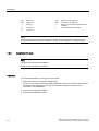
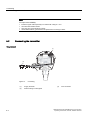
Connecting the transmitter
Requirement
ದ
Figure 5-1
5-2
Connecting
(1)
Supply terminals
(2)
Shield coating on cable gland
(3)
Bus connection
SITRANS P300 with PROFIBUS-PA communication
Operating Instructions, 06/2005, A5E00414588-02
Connecting
5.2 Connecting the transmitter
Procedure
To connect the transmitter, proceed as follows:
1. Strip approx. 14 cm of the cable.
2. Unscrew the cover of the electrical cable compartment.
3. Insert the cable set via the cable gland through a guide channel.
The guide channel connects the cable gland with the cable compartment.
4. Connect the strands to the supply terminals (1) "+" and "-".
The device is polarity-independent.
5. Attach the shielding to the cable gland (2).
6. Screw the cover back into place.
SITRANS P300 with PROFIBUS-PA communication
Operating Instructions, 06/2005, A5E00414588-02
5-3
Connecting
5.2 Connecting the transmitter
5-4
SITRANS P300 with PROFIBUS-PA communication
Operating Instructions, 06/2005, A5E00414588-02
6
Operation
6.1
Overview of operation
Introduction
The following description provides an overview of the operating functions which can be
executed with the pressure transmitter and the safety information which is to be observed
when doing so. Since the transmitter can be operated on site and via PROFIBUS, first the
local operation and then the PROFIBUS operating functions will be described.
If there are references to further information on an aspect described here, these will always
be found at the end of a chapter under "See also".
Overview
Contents:
• Safety information for operation
• Information on operation
• Digital display
• Local operation
Overview of operating functions
You can operate the basic settings of the pressure transmitter using the buttons on the
device. The entire range of settings can be operated via PROFIBUS.
SITRANS P300 with PROFIBUS-PA communication
Operating Instructions, 06/2005, A5E00414588-02
6-1
Operation
6.2 Safety information for operation
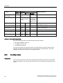
The following table describes the basic operating functions offered by a device with a digital
display.
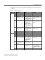
Table 6-1
Operating functions
Function
With buttons
Over PROFIBUS
Electrical damping
Yes
Yes
Zero point calibration (position correction)
Yes
Yes
Key lock and write protection
Yes
Yes
Measured value display
Yes
Yes
Unit
Yes
Yes
Bus address
Yes
Yes
Device operation type
Yes
Yes
Decimal point
Yes
Yes
Zero point drift
Yes
Yes
LO calibration
Yes
Yes
HI calibration
Yes
Yes
Customized characteristic curve
No
Yes
Diagnostics function
No
Yes
Measurement type
No
Yes
Further operating functions are accessible via PROFIBUS for special applications.
6.2
Safety information for operation
Notice
If you have set the basic functions of the pressure transmitter as user defined, the display
and measurement output terminal can be adjusted such that the true process pressure is not
reproduced.
The basic variables should therefore be checked prior to commissioning.
6.3
Information on operation
Introduction
The following tips apply to on-site operation of the pressure transmitter:
• The device always counts successively upward from the lowest displayed point.
6-2
SITRANS P300 with PROFIBUS-PA communication
Operating Instructions, 06/2005, A5E00414588-02
Operation
6.4 Digital display
If you hold the <UP> button down for a longer period, it counts to the next highest
displayed point. This process allows for a rough adjustment over a wide range. For fine
adjustment, use the <UP> or <DOWN> button again. Press the button again.
Violations of the measured value limits are displayed on the digital display with
or .
• To operate the device locally, the key lock must be released.
• The readout of data is always possible locally or also over PROFIBUS.
• If write protection is deactivated, changing the data is possible locally as well as over the
PROFIBUS.
Note
If more than 2 minutes has passed since the last key was pressed, the setting is
automatically saved and the device automatically returns to the measured value display.
6.4
Digital display
6.4.1
Elements of the digital display
Structure
Figure 6-1
(1)
Structure of the digital display
Measured value
(5)
Violation of lower limit
(2)
Unit/error code
(6)
Symbol for measured value
(3)
Root display
(7)
Violation of higher limit
(4)
Mode/button lock
(8)
Communication display
SITRANS P300 with PROFIBUS-PA communication
Operating Instructions, 06/2005, A5E00414588-02
6-3
Operation
6.4 Digital display
Description
The digital display is used for the local display of the measured value (1) with:
• Unit (2)
• Mode (4)
• Symbol (6)
• Status (5) and (7)
The measured value display (1) presents the measurement in a selectable physical unit
according to the customer settings.
The displays Violation of lower limit (5) and Violation of upper limit (7) are also referred to as
statuses as they have meanings dependent on the settings.
The communications display (8) shows that communication with the PROFIBUS is active.
6.4.2
Units display
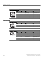
Description
The unit display consists of five 14-segment fields for displaying the unit as a percentage
value or physical unit.
Display
Figure 6-2
6.4.3
Example for measured pressure value display
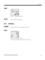
Error display
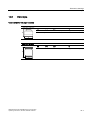
Description
If hardware faults, software errors or diagnostic alarms occur in the transmitter, the message
"Error" appears in the measured value display.
A status code appears in the lower line of the digital display indicating the type of error. This
diagnostic information is also available via PROFIBUS.
Error messages are displayed for about 10 seconds after the occurrence of the error.
6-4
SITRANS P300 with PROFIBUS-PA communication
Operating Instructions, 06/2005, A5E00414588-02
Operation
6.4 Digital display
Display
Figure 6-3
Example of error message
See also
Overview of status codes (Page A-2)
6.4.4
Mode display
Description
The selected active mode is shown in the mode display.
Display
Figure 6-4
Example for mode display
In the example, a damping of 0.2 seconds was set in mode 4.
SITRANS P300 with PROFIBUS-PA communication
Operating Instructions, 06/2005, A5E00414588-02
6-5
Operation
6.5 Local operation
6.4.5
Status display
Description
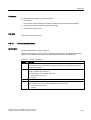
The arrows of the status display have a different meaning depending on the mode setting.
The table below shows the meanings of the arrows in the respective functions.
Meaning
Table 6-2
Meaning of the arrow displays
Function
Mode
Measured value display
Display
Display
Pressure exceeds the upper
sensor limit.
Pressure falls below the lower
sensor limit.
Adjusting damping
4
Exceeds of the upper
damping value
Exceeds of the lower damping
value
LO calibration
19
–
Calibration span too low
HI calibration
20
Calibration span too high
–
Alarm
Upper alarm limit reached
Lower alarm limit reached
Warning
Upper warning limit reached
Lower warning limit reached
See also
Overview of status codes (Page A-2)
6.5
Local operation
6.5.1
Local control elements
Introduction
The transmitter can be operated on site with the keys (buttons). Selectable modes can be
used to choose and execute the functions described in the table.
6-6
SITRANS P300 with PROFIBUS-PA communication
Operating Instructions, 06/2005, A5E00414588-02
Operation
6.5 Local operation
Control elements
Figure 6-5
Position of keys and digital display
(1)
Digital display
(3)
Test connector
(2)
Keys
Operating functions
Table 6-3
Operating functions via keys
Function
Mode
Key function
<MODE>
<UP>
Measured value
The
modes
are
selected
here.
Electrical damping
4
Zero point calibration
(position correction)
7
Display, explanations
<DOWN> <UP> and
<DOWN>
The current measured value is displayed as
you have adjusted it in the "Measured value
display, mode 13" function.
Damping
higher
Damping
lower
Time constant T63 in seconds
Adjustment range: 0.0 s to 100.0 s
Execute
Pressurizing transmitter for gauge pressure
or level
Transmitter for absolute pressure: Mode
deactivated.
Measured value in pressure unit
Key lock or function
lock
10
Change
Save
Change
–
-L
None
Write protection
Operation via PROFIBUS not
possible.
SITRANS P300 with PROFIBUS-PA communication
Operating Instructions, 06/2005, A5E00414588-02
6-7
Operation
6.5 Local operation
Function
Display, explanations
Mode
Key function
<MODE>
<UP>
Source of measured
value display
13
Select from various
options.
–
Unit
14
Select from the table
for measured values
display.
In each case
Physical unit
the first value
from the table
of the physical
unit
Bus address
15
Larger
<DOWN> <UP> and
<DOWN>
Smaller
Selection of different variables
Address on PROFIBUS
Value between 0 and 126
Device operation type
16
Select
Select
Select device operating type
Decimal point
17
To the
right
To the
left
Position of decimal point
Zero point adjustment
18
LO calibration
19
Preset
larger
Preset
smaller
Execute
Calibrate lower point on characteristic
HI calibration
20
Preset
larger
Preset
smaller
Execute
Calibrate upper point on characteristic
Display of current measurement range
Definition: Zero point adjustment
After the following functions, the measurement range is changed:
• Zero-point calibration (mode 7)
• LO calibration (mode 19)
• HI calibration (mode 20)
If you have executed one of these functions, the measurement range has changed. This
changed, remaining measurement range is called the zero-point adjustment. The value
displayed by the device in mode 18 is a positive pressure.
6.5.2
Operating via keys
Introduction
This overview provides you with most important safety information required to operate the
pressure transmitter. The overview also instructs you how to adjust the operating functions
on site.
6-8
SITRANS P300 with PROFIBUS-PA communication
Operating Instructions, 06/2005, A5E00414588-02
Operation
6.5 Local operation
Requirement
Warning
Intrinsically safe circuits
With intrinsically-safe circuits, use only certified power supplies or couplers appropriate for
the transmitter.
Warning
Specific type examination certificates
Observe the provisions of the EG type test certification or the local test certification valid for
your country.
Note
The housing should be cleaned to prevent dirt and moisture entering the device.
To operate the device via the keys, the key lock must be released.
Procedure
The device is set to measured value display by default.
To adjust the operating functions, proceed as follows:
1. Unscrew the cover.
2. Press the <MODE> key until the desired mode is displayed.
3. Press the <UP> or <DOWN> key until the desired value is displayed.
4. Press the <MODE> key.
This saves the values and the device then jumps to the next mode.
5. Screw the cover back into place.
Note
If more than 2 minutes has passed since the last key was pressed, the setting is
automatically saved and the device automatically returns to the measured value display.
SITRANS P300 with PROFIBUS-PA communication
Operating Instructions, 06/2005, A5E00414588-02
6-9
Operation
6.5 Local operation
6.5.3
Adjusting electrical damping
Introduction
In mode 4, set the electrical damping. The time constants of the electrical damping can be
set between 0 and 100 seconds in 0.1 second steps using the buttons. This electrical
damping also acts as the device's own basic damping.
Requirement
You are familiar with the correct operation of the transmitter and the associated safety
information.
The basic calibration of the steps is a 0.1 second interval. The longer you depress the <UP>
and <DOWN> key, the greater the steps.
Procedure
To adjust the electrical damping, proceed as follows:
1. Set mode 4.
2. Adjust the desired damping.
3. Save with the <Mode> key.
Result
Electrical damping has been adjusted to the desired time constant.
The electrical damping only has an effect on the output of the analog input function block.
See also
Electrical damping (Page 7-17)
Operating via keys (Page 6-8)
6.5.4
Zero point calibration
Introduction
The zero point is calibrated in mode 7. Zero point calibration corrects zero point errors
resulting from the installation position of the pressure transmitter. The device type
determines the way in which you proceed.
SIMATIC PDM shows you the sum of all zero-point corrections.
6-10
SITRANS P300 with PROFIBUS-PA communication
Operating Instructions, 06/2005, A5E00414588-02
Operation
6.5 Local operation
Correct this offset in the following boundaries:
Gauge pressure
-100 %, but not more than -1 bar,
Absolute pressure
Mode 7 blocked
up to +100 % of the nominal measurement range
Requirement
You are familiar with the correct operation of the transmitter and the associated safety
information.
Zero point calibration for gauge pressure transmitter
To calibrate the zero point, proceed as follows:
1. Pressurize the transmitter.
2. Set mode 7.
3. Press the <UP> and <DOWN> keys simultaneously for 2 seconds.
4. Save with the <Mode> key.
Result
The value 0 id displayed in the digital display, with the appropriate number of decimal points
depending on:
• Nominal measurement range
• Pressure unit selected
See also
Operating via keys (Page 6-8)
6.5.5
Locking keys
Introduction
Functions which can generally be carried out via the keys can be locked in mode 10.
Application examples for a lock include backup of the saved parameters.
SITRANS P300 with PROFIBUS-PA communication
Operating Instructions, 06/2005, A5E00414588-02
6-11
Operation
6.5 Local operation
Lock options
You have the following lock options on the pressure transmitter:
Table 6-4
Meaning of the lock modes
Lock mode
Meaning
--
The device can be operated by means of the keys and PROFIBUS communication.
L
Write protection
Operation via the keys and PROFIBUS communication is locked.
Exception:
• Releasing key lock
Requirement
You are familiar with the correct operation of the transmitter and the associated safety
information.
Note
Check the measured value display function to see whether the desired setting is displayed.
Procedure
To lock the keys, proceed as follows:
1. Set mode 10.
2. Select the desired lock mode.
3. Confirm the lock mode by pressing <MODE>.
See also
Operating via keys (Page 6-8)
Releasing key or function lock (Page 6-12)
Key lock and write protection (Page 7-17)
6.5.6
Releasing key or function lock
Procedure
To release write protection for PROFIBUS (L) using the keys, proceed as follows:
1. Set mode 10.
2. Press the <UP> and <DOWN> keys simultaneously for 5 seconds.
6-12
SITRANS P300 with PROFIBUS-PA communication
Operating Instructions, 06/2005, A5E00414588-02
Operation
6.5 Local operation
6.5.7
Source of measured value display
Introduction
In mode 13, select a variable which represents the source of the measured value display.
The variable is based on the measurement type set at the factory or through the bus. The
measurement type cannot be set locally.
The measurement type options available can be set in SIMATIC PDM using the "transmitter
type" parameter. Find the following values under this parameter:
• Pressure
• Flow, not relevant for gauge and absolute pressure
• Level
• Volume
Requirement
You are familiar with the correct operation of the transmitter and the associated safety
information.
Procedure
To select the source for the measured value display, proceed as follows:
1. Set mode 13.
2. Select the variable.
3. Save with the <Mode> key.
Parameter
The following tables give the meaning of the variables, depending on the value of the
"transmitter type" parameter. This allows you to select the units available in mode 14.
Table 6-5
Measurement type "Pressure"
Source of measured value display
Variable
Available unit
OUT
(P)
Pressure
(U)
User specific
From analog input function block:
[0] : Output :
From pressure transducer block:
[1] : Secondary variable 1
SEC 1
(P)
Pressure
[2] : Measurement value (primary
variable)
PRIM
(P)
Pressure
[3] : Sensor temperature
TMP S
(T)
Temperature
[4] : Electronics temperature
TMP E
(T)
Temperature
SITRANS P300 with PROFIBUS-PA communication
Operating Instructions, 06/2005, A5E00414588-02
6-13
Operation
6.5 Local operation
Source of measured value display
[5] : Secondary variable 3:
Variable
Available unit
SEC 3
(M)
Mass / mass flow
Flow not relevant for gauge and
absolute pressure
[7] : Raw pressure value
SENS
(P)
Pressure
TOTAL
(V)
Volume
(ΣM) *)
Total mass flow
From totalizer function block:
[6] : Totalizer output
Flow not relevant for gauge and
absolute pressure
Table 6-6
Measurement type "Level"
Source of measured value display
Variable
Available unit
OUT
(L)
Level
(U)
User specific
From analog input block:
[0] : Output
From pressure transducer block:
[1] : Secondary variable 1
SEC 1
(P)
Pressure
[2] : Measurement value (primary
variable)
PRIM
(L)
Level
[3] : Sensor temperature
TMP S
(T)
Temperature
[4] : Electronics temperature
TMP E
(T)
Temperature
[5] : Secondary variable 3:
SEC 3
(M)
Mass / mass flow
Flow not relevant for gauge and
absolute pressure
[7] : Raw pressure value
SENS
(P)
Pressure
TOTAL
(V)
Volume
(ΣM) *)
Total mass flow
From totalizer function block:
[6] : Totalizer output
Flow not relevant for gauge and
absolute pressure
*) The option of selecting the physical unit is additionally determined by the channel setting
(mass or volume) of the analog input and totalizer function blocks.
Table 6-7
Measurement type "Volume"
Source of measured value display
Variable
Available units
OUT
(V)
Volume
(U)
User specific
From analog input block:
[0] : Output
From pressure transducer block:
6-14
[1] : Secondary variable 1
SEC 1
(P)
Pressure
[2] : Measurement value (primary
variable)
PRIM
(V)
Volume
[3] : Sensor temperature
TMP S
(T)
Temperature
SITRANS P300 with PROFIBUS-PA communication
Operating Instructions, 06/2005, A5E00414588-02
Operation
6.5 Local operation
Source of measured value display
Variable
Available units
[4] : Electronics temperature
TMP E
(T)
Temperature
[5] : Secondary variable 3:
SEC 3
(M)
Mass / mass flow
Flow not relevant for gauge and
absolute pressure
[7] : Raw pressure value
SENS
(P)
Pressure
TOTAL
(V)
Volume
(ΣM) *)
Total mass flow
From totalizer function block:
[6] : Totalizer output
Flow not relevant for gauge and
absolute pressure
*) The option of selecting the physical unit is additionally determined by the channel setting
(mass or volume) of the analog input and totalizer function blocks.
See also
Block model for collection and processing of measured values (Page 7-1)
Pressure transducer block (transducer block 1) (Page 7-4)
Operating via keys (Page 6-8)
6.5.8
Unit
Introduction
In mode 14, set the physical unit in which the device's measured value display should be
represented.
Requirement
You are familiar with the correct operation of the transmitter and the associated safety
information.
You have already selected the desired source for the measured value display in mode 13.
Procedure
To adjust the physical unit, proceed as follows:
1. Set mode 14.
The physical unit used appears in the lower line of the digital display.
2. Select a unit.
3. Save with the <Mode> key.
The following tables show the physical units available in each measurement type.
SITRANS P300 with PROFIBUS-PA communication
Operating Instructions, 06/2005, A5E00414588-02
6-15
Operation
6.5 Local operation
Units
Table 6-8
Unit
Identifier
Display
Pa
1130
Pa
MPa
1132
MPa
kPa
1133
KPa
hPa
1136
hPa
bar
1137
bar
mbar
1138
mbar
torr
1139
Torr
atm
1140
ATM
psi
1141
PSI
g/cm²
1144
G/cm2
kg/cm²
1145
KGcm2
inH2O
1146
INH2O
inH2O(4°C)
1147
INH2O
mmH2O
1149
mmH2O
mmH2O(4°C)
1150
mmH2O
ftH2O
1152
FTH2O
inHg
1155
IN HG
mmHg
1157
mm HG
Table 6-9
6-16
Unit for pressure (P)
Unit for volume (V)
Unit
Identifier
Display
m3
1034
m3
dm3
1035
dm3
cm3
1036
cm3
mm3
1037
mm3
l
1038
L
cl
1039
cL
ml
1040
mL
hl
1041
hL
in3
1042
IN3
ft3
1043
FT3
yd3
1044
Yd3
pint (US)
1046
Pint
quart (US)
1047
Quart
US gallon
1048
GAL
imp. gallon
1049
ImGAL
bushel
1050
BUSHL
SITRANS P300 with PROFIBUS-PA communication
Operating Instructions, 06/2005, A5E00414588-02
Operation
6.5 Local operation
Unit
Identifier
Display
barrel
1051
bbl
barrel liquid
1052
bblli
Table 6-10
Unit for level (L)
Unit
Identifier
Display
m
1010
m
cm
1012
cm
mm
1013
mm
ft
1018
FT
in
1019
IN
yd
1020
Yd
Table 6-11
Unit for mass (M)
Unit
Identifier
Display
kg
1088
KG
g
1089
G
t
1092
T
oz
1093
oz
lb
1094
lb
STon
1095
STon
LTon
1096
LTon
Identifier
Display
Table 6-12
Unit for temperature (T)
Unit
K
1000
K
°C
1001
°C
°F
1002
°F
°R
1003
°R
SITRANS P300 with PROFIBUS-PA communication
Operating Instructions, 06/2005, A5E00414588-02
6-17
Operation
6.5 Local operation
Table 6-13
Unit for user-specific (U)
Unit
Identifier
arbitrary
1995
Display
Max. 16 characters,
If more than 5 characters, the digital display shows the unit as a
ticker.
The input of the characters to be displayed can only be
performed through the PROFIBUS.
%
1342
%
Note
The profile allows a much larger number of possible units. There is no limitation on some
physical values special to the output of the analog input function block. For instance, if you
have selected a unit with SIMATIC PDM which does not appear in the corresponding valid
list, the current measurement value will be shown without a unit in the measured value
display.
See also
Units of the pressure transducer block (Page 7-8)
Operating via keys (Page 6-8)
6.5.9
Bus address
Introduction
The node address of the device on the PROFIBUS, the so-called bus address, is set in
mode 15. The permissible range runs from 0 to 126.
Requirement
You are familiar with the correct operation of the transmitter and the associated safety
information.
Note
Do not change the bus address of the device while your system is running. The device will
then no longer be visible from the application program.
6-18
SITRANS P300 with PROFIBUS-PA communication
Operating Instructions, 06/2005, A5E00414588-02
Operation
6.5 Local operation
Procedure
To change the bus address, proceed as follows:
1. Set mode 15.
The currently set bus address of the device appears in the measured value display.
2. Select the bus address within the permissible range.
3. Save with the <Mode> key.
See also
Operating via keys (Page 6-8)
6.5.10
Device operation type
Introduction
Set the device operation type in mode 16.
The device operation type [1] is preset on the pressure transmitter. Other device operation
types are only suitable if you have set another operation type through PROFIBUS.
Table 6-14
Device operation type
Display
Meaning
[0]
Profile-compatible:
Exchangeable for transmitters with PROFIBUS PA Profile 3.0, with analog input function
block, without totalizer
[1]
Delivery state
Profile-compatible with extensions:
Full functionality of the SITRANS P300 with:
• Analog input function block
• Totalizer
[2]
Not relevant
[128]
Profile-compatible:
Exchangeable for transmitter with PROFIBUS PA Profile 3.0 with:
• Analog input function block
• Totalizer.
SITRANS P300 with PROFIBUS-PA communication
Operating Instructions, 06/2005, A5E00414588-02
6-19
Operation
6.5 Local operation
Requirement
You are familiar with the correct operation of the transmitter and the associated safety
information.
Procedure
To change the device operation type, proceed as follows:
1. Set mode 16.
The current operation type appears in the measured value display.
2. Select the device operation type.
The local operation type must match the operation type in PROFIBUS.
3. Save with the <Mode> key.
Note
Each device operation type is assigned a particular device master data file (GSD file).
If the configuration of your PROFIBUS-PA strand does not correspond to the device
operation type selected, the device will not start periodic data exchange. Successful
establishment of communications can be seen by the communications indicator "o" in the
upper left of the digital display.
Note
If the device is exchanging period data, no change is possible to the device operating
type.
Table 6-15
Display
Device master data file
File name
"?" stands for the GSD version.
[0]
pa_?9700.gsd
[1]
siem8121.gsd
[2]
sip1804B.gsd
[128]
pa_?9740.gsd
See also
Errors (Page 10-1)
Operating via keys (Page 6-8)
6-20
SITRANS P300 with PROFIBUS-PA communication
Operating Instructions, 06/2005, A5E00414588-02
Operation
6.5 Local operation
6.5.11
Position of the decimal point
Introduction
Set the position of the decimal point in mode 17. Measured values can be displayed by the
device with up to four decimal places.
Requirement
You are familiar with the correct operation of the transmitter and the associated safety
information.
Procedure
To move the decimal point, proceed as follows:
1. Set mode 17.
A mask appears in the digital display showing the current position of the decimal point.
2. Select the desired display format.
8.8888
88.888
888.88
8888.8
88888
3. Save with the <Mode> key.
Note
If you set the decimal point too far to the right, the resolution of the display may be too
low. The digital display may show, for instance, "0" instead of "0.43".
If you set the decimal point too far to the left, it can overflow. Then the digital display will
show the character sequence 9.9.9.9.9 and error code F_004 instead of the measured
value.
See also
Operating via keys (Page 6-8)
Errors (Page 10-1)
SITRANS P300 with PROFIBUS-PA communication
Operating Instructions, 06/2005, A5E00414588-02
6-21
Operation
6.5 Local operation
6.5.12
Display of the zero-point adjustment
Introduction
The zero-point adjustment is shown in mode 18.
Requirement
You are familiar with the correct operation of the transmitter and the associated safety
information.
Procedure
To display the current zero-point adjustment, proceed as follows:
1. Set mode 18.
The current zero-point adjustment appears in the digital display.
2. Close with the <Mode> key.
See also
Operating via keys (Page 6-8)
6.5.13
LO calibration
Introduction
The slope of the characteristic is changed in mode 19. This rotates the characteristic around
setting point HI.
This function replaces the zero-point calibration (mode 7) which is not permitted for absolute
pressure transmitters.
The unit in which you want to calibrate is set using the following functions:
• In mode 13, set the source of the measured value display[7] : Raw pressure value,
variable SENS.
• In mode 14, select the desired pressure unit.
Note
If you change this setting, the measurement range can be restricted to the point that the
permissible sensor limits are violated even with small pressure changes.
6-22
SITRANS P300 with PROFIBUS-PA communication
Operating Instructions, 06/2005, A5E00414588-02
Operation
6.5 Local operation
Requirement
You are familiar with the correct operation of the transmitter and the associated safety
information.
Procedure
In order to calibrate an LO, proceed as follows:
1. Set mode 19.
The digital display shows the value of the last calibration procedure, with the appropriate
unit.
2. Create the reference pressure.
3. Press the <UP> or <DOWN> key.
The measured value display switches to the current pressure value. Using the <UP> and
<DOWN> keys, you can enter the reference value starting from there.
4. Press the <UP> and <DOWN> keys simultaneously for 2 seconds.
5. Save with the <Mode> key.
Result
If the calibration was successful, the current measurement value of the device will be
displayed, and will correspond to the calibration value as long as the reference pressure is
still applied.
If you switch to the measured value display without taking a sufficiently large calibration span
into account, the pressure status "Bad" B_004 will be displayed.
The shutdown logic of the function block is activated and the output shows the status
"Unsure" U_0xx, depending on the configuration.
If the two calibration points are too close together, status F_006 is displayed. The smallest
calibration span depends on the nominal measurement range. Select either the higher
reference pressure in mode 20, or the lower reference pressure in mode 19.
As long as mode 19 is active, you can repeat this procedure as often as necessary.
View LO calibration
To view the LO calibration, proceed as follows:
1. Set mode 19.
The digital display shows the value of the last calibration procedure, with the appropriate
unit.
2. Leave the mode by pressing <MODE>.
SITRANS P300 with PROFIBUS-PA communication
Operating Instructions, 06/2005, A5E00414588-02
6-23
Operation
6.5 Local operation
See also
Calibrating the sensor (Page 7-26)
Errors (Page 10-1)
Operating via keys (Page 6-8)
6.5.14
HI calibration
Introduction
The slope of the characteristic is changed in mode 20. This rotates the characteristic around
setting point LO.
The unit in which you want to calibrate is set using the following functions:
• In mode 13, set the source of the measured value display[7] : Raw pressure value,
variable SENS.
• In mode 14, select the desired pressure unit.
Note
If you change this setting, the measurement range can be restricted to the point that the
permissible sensor limits are violated even with small pressure changes.
Procedure
To calibrate HI, proceed as follows:
1. Set mode 20.
The digital display shows the value of the last calibration procedure, with the appropriate
unit.
2. Create the reference pressure.
3. Press the <UP> or <DOWN> key.
The measured value display switches to the current pressure value. Using the <UP> and
<DOWN> keys, you can enter the reference value starting from there.
4. Press the <UP> and <DOWN> keys simultaneously for 2 seconds.
5. Save with the <Mode> key.
Result
If the calibration was successful, the current measurement value of the device will be
displayed, and will correspond to the calibration value as long as the reference pressure is
still applied.
6-24
SITRANS P300 with PROFIBUS-PA communication
Operating Instructions, 06/2005, A5E00414588-02
Operation
6.5 Local operation
If you switch to the measured value display without taking a sufficiently large calibration span
into account, the pressure status "Bad" B_004 will be displayed.
The shutdown logic of the function block is activated and the output shows the status
"Unsure" U_0xx, depending on the configuration.
If the two calibration points are too close together, status F_006 is displayed. The smallest
calibration span depends on the nominal measurement range. Select either the higher
reference pressure in mode 20, or the lower reference pressure in mode 19.
As long as mode 20 is active, you can repeat this procedure as often as necessary.
Viewing the HI calibration
To view the HI calibration, proceed as follows:
1. Set mode 20.
The digital display shows the value of the last calibration procedure, with the appropriate
unit.
2. Leave the mode by pressing <MODE>.
See also
Calibrating the sensor (Page 7-26)
Errors (Page 10-1)
Operating via keys (Page 6-8)
SITRANS P300 with PROFIBUS-PA communication
Operating Instructions, 06/2005, A5E00414588-02
6-25
Operation
6.5 Local operation
6-26
SITRANS P300 with PROFIBUS-PA communication
Operating Instructions, 06/2005, A5E00414588-02
Operating functions over PROFIBUS
7.1
Communication structure for PROFIBUS PA
7.1.1
Overview
7
This chapter describes the processing method of the device-specific function blocks using a
graphical block model which is resolved into its individual layers step by step. Knowledge of
the physical block is assumed: It will thus not be explained in this chapter.
Definition: Function block
A named block consisting of one or more inputs, outputs, and included parameters.
Function blocks represent the basic automation functions executed by an application in a
way as independent as possible from the details of I/O devices and the network. Each
function block processes input parameters using a specified algorithm and a set of internally
stored parameters. They produce output parameters which are available for use inside the
same function block application or by other function block applications.
7.1.2
Block model for collection and processing of measured values
The device functions are subdivided into blocks of different task areas. They can be
parameterized during asynchronous data transmission.
SITRANS P300 with PROFIBUS-PA communication
Operating Instructions, 06/2005, A5E00414588-02
7-1
Operating functions over PROFIBUS
7.1 Communication structure for PROFIBUS PA
)XQFWLRQEORFN
$QDORJLQSXW
6
7
3UHVVXUHWUDQVGXFHUEORFN
5HODWLYHSUHVVXUH
$EVROXWHSUHVVXUHDQG
6HQVRUWHPSHUDWXUH
)XQFWLRQEORFN
7RWDOL]HU
7
6
352),%863$
S
(OHFWURQLFVWHPSHUDWXUH
WUDQVGXFHUEORFN
/RFDORSHUDWLRQ
DQGGLJLWDOGLVSOD\
Figure 7-1
Block circuit diagram of collection and processing of measured values
p
Pressure
T
Temperature
S
Sensor
Pressure transducer block
When measuring levels, the necessary conversions of the measurement value are
performed in the pressure transducer block. The output value is the linearized and
temperature-compensated measurement result.
The pressure transducer block also processes the temperature measurement of the
pressure sensor and monitors the pressure and temperature limits.
Example
In hydrostatic level measurement, the pressure transducer block converts the incoming
pressure value into height or volume.
Electronic temperature transducer block
The electronics temperature transducer block executes the required temperature
measurement functions and monitors the permissible temperature limits.
7-2
SITRANS P300 with PROFIBUS-PA communication
Operating Instructions, 06/2005, A5E00414588-02
Operating functions over PROFIBUS
7.1 Communication structure for PROFIBUS PA
Analog input function block
The analog input function block further processes the selected measurement value and
passes it on to the automation task.
Example
For a container full of water, you measure the volume. The analog input function block
calculates the container volume [m3] in a user-specific volume unit [bottles]. The output of
this block gives the measured value and the corresponding status on the PROFIBUS.
Totalizer function block
The totalizer function block is not relevant for gauge or absolute pressure.
Local operation and digital display
The digital display represents the desired measured value with its physical unit. You can
select different functions for local operation.
Connection between blocks via parameters
The output values of the transducer blocks for pressure and electronics temperature can be
fed to the analog input and totalizer function blocks as input values for further processing. To
do this, the parameter "Channel" must be correctly set in each function block.
Table 7-1
Connection between blocks
Transducer block
Output value
(Parameters)
Usable in the analog input
function block
Pressure
Temperature
X
Secondary variable 1
X
Secondary variable 2
X
Measurement value (primary
variable)
X
Secondary variable 3
X
Electronics temperature
X
Electronics temperature
Parameters for measured value display
The values of the following parameters from the measurement and function blocks can be
shown on the digital display. The parameter "Source for display" must be set appropriately.
SITRANS P300 with PROFIBUS-PA communication
Operating Instructions, 06/2005, A5E00414588-02
7-3
Operating functions over PROFIBUS
7.1 Communication structure for PROFIBUS PA
Table 7-2
Display on digital display
Block
Parameter
On digital display
displayable
Pressure transducer block
Temperature
X
Secondary variable 1
X
Secondary variable 2
Measurement value
(primary variable)
X
Secondary variable 3
X
Raw pressure value
X
Electronics temperature transducer block Electronics temperature
X
Analog input function block
Output
X
Totalizer function block
Totalizer output
X
See also
Cyclical data transfer (Page 8-1)
Acyclic data transfer (Page 8-6)
Source of measured value display (Page 6-13)
7.1.3
Pressure transducer block
7.1.3.1
Pressure transducer block (transducer block 1)
The following figure shows the signal flow of measurement values from the sensor cell
through the pressure transducer block into the appropriate output values, e.g. temperature,
measurement value (primary variable), etc. The parameters of the individual functions, e.g.
measurement range, output range, etc. can be changed using acyclic access.
7-4
SITRANS P300 with PROFIBUS-PA communication
Operating Instructions, 06/2005, A5E00414588-02
Operating functions over PROFIBUS
7.1 Communication structure for PROFIBUS PA
=HURSRLQW
FDOLEUDWLRQ
/LQHDUL
]DWLRQ
W\SH
6FDOLQJ
0DVV
3URFHVVYDULDEOH
'HQVLW\
2SHUDWLQJUDQJH
1RUPDOL
]DWLRQ
/LQHDUL]HG3UHVVXUHUDZYDOXH
7HVWLQJ
VHQVRU
OLPLWV
1RUPDOL]HG3UHVVXUHUDZYDOXH
&OHDQHG3UHVVXUHUDZYDOXH
0HDVXULQJUDQJH
&DOLEUD
WLRQ
S
)LQDOYDOXHPD[
6WDUWYDOXHPLQ
6
3UHVVXUHUDZYDOXH
0HDVXULQJFHOO
=HURSRLQWDGMXVWPHQW
8SSHUWULPSRLQW
/RZHUWULPSRLQW
6PDOOHVWFDOLEUDWLRQVSDQ
8QLW3UHVVXUHUDZYDOXH
3DUDPHWHUYLDDF\FOLFDFFHVV
0XOWLSOL
FDWLRQ
7
Figure 7-2
6(&
35,0
6(&
6(&
7
6
Function groups of the pressure transducer block
p
Pressure
SEC 1
Secondary variable 1
S
Sensor
SEC 2
Secondary variable 2
T
Temperature
PRIM
Primary variable
SEC 3
Secondary variable 3
Functional principle
The raw pressure value first passes through a calibration. The resulting cleaned-up pressure
value is checked for sensor limits. Any violation of the limits results in status "Bad" and a
diagnostic error of "error collecting measured value". The cleaned-up pressure value is
stored in SEC 1.
SITRANS P300 with PROFIBUS-PA communication
Operating Instructions, 06/2005, A5E00414588-02
7-5
Operating functions over PROFIBUS
7.1 Communication structure for PROFIBUS PA
Then, it is subjected to a normalization, where the input signal is expressed in the range 0 to
10 (percentage/100). The normalized pressure value is stored in SEC 2.
Afterwards, depending on the measurement task, it is fed through one of four different
linearization types. Scaling uses the preset working range (minimum and maximum values)
to determine the normalized and linearized measured value (pressure, height, or volume) of
the actual process variable. This is stored in PRIM.
By means of a multiplication with the density the volume is used to compute the mass. This
is stored in SEC 3.
The temperature value of the pressure sensor is available in the "temperature" parameter.
See also
Acyclic data transfer (Page 8-6)
7.1.3.2
Linearization type function group
The normalized pressure is fed through the linearization algorithms for adjustment to the
various process requirements, as shown in the following figure. The algorithm is switched
using the "Characteristic type" parameter.
,QVHWSRLQWRIWKH
URRWIXQFWLRQ
&UHHSTXDQWLW\
VXSSUHVVLRQ
&KDUDFWHULVWLFW\SH
Figure 7-3
7-6
Linearization type function group
0
Linear
1
User-defined "table"
10
Root,
not relevant for gauge and absolute
pressure
240
Root/table,
not relevant for gauge and absolute
pressure
SITRANS P300 with PROFIBUS-PA communication
Operating Instructions, 06/2005, A5E00414588-02
Operating functions over PROFIBUS
7.1 Communication structure for PROFIBUS PA
Table 7-3
Available linearization functions
Measurement task Linearization symbol
Characterist Description
ic type
Pressure
measurement
-
Linear
No linearization
Level: Height
-
Linear
No linearization
User
defined
(table)
Linearization of container characteristics.
Level: Volume
The relationship between level and volume
is described using a maximum of 31 set
points at arbitrary intervals.
To input a characteristic curve, select the characteristic type "user-defined (table)". Enter the
"New number of set points" which you will later want to enter.
The set points must always be entered in pairs. For each point x[n] in the working range, a
point y[n] is required.
The device checks which pair of set points bracket the pressure (secondary variable 1)
gauge to the measurement range. To convert the pressure to the measured value (primary
variable), the device interpolates on a line between the set points.
\
[>@\>@
[>@\>@
\
[>@\>@
[>@\>@
[>@\>@
[>@\>@
[
Figure 7-4
[
Entry of a user-defined characteristic using set points x(i), y(i)
x
Measurement range, here e.g. pressure (secondary variable 1)
y
Working range, here e.g. volume, measured value (primary variable)
SITRANS P300 with PROFIBUS-PA communication
Operating Instructions, 06/2005, A5E00414588-02
7-7
Operating functions over PROFIBUS
7.1 Communication structure for PROFIBUS PA
7.1.3.3
Units of the pressure transducer block
In the pressure transducer block you have the option of setting units in four different places.
Depending on the measurement type, units are allowed from the following measurement
functions:
Table 7-4
Overview of available units
Variable
Measurement type
Pressure
Level
Volume
Raw pressure value
P
P
P
Secondary variable 1
P
P
P
Measurement value
(primary variable)
P
L
V
Secondary variable 3
---
---
---
P
Pressure
L
Level
V
Volume
For the measurement values (primary variables) you can also set the unit "%" for all
measurement types.
Secondary variable 2 is a value normalized to one in all measurement types. The unit is fixed
at "none".
See also
Unit (Page 6-15)
7.1.4
Electronics temperature transducer block
The electronics temperature transducer block is manufacturer-specific and not described in
the profile. It has the task of monitoring the internal temperature of the device electronics and
cannot change the pressure value, only its status.
The permissible limits correspond to those of the permissible ambient temperature. If a limit
is violated, the status changes to "GOOD – Active Critical Alarm – High/Low-limit". The
status of the cleaned-up pressure value in the pressure transducer block receives the status
"UNCERTAIN – Value not accurate – high/low-limit". This procedure is accompanied by a
PROFIBUS diagnostic message "Electronics temperature too high".
There are also peak indicators for maximum and minimum values available.
7-8
SITRANS P300 with PROFIBUS-PA communication
Operating Instructions, 06/2005, A5E00414588-02
Operating functions over PROFIBUS
7.1 Communication structure for PROFIBUS PA
See also
Min/max pointer (Page 7-22)
Status (Page 8-4)
7.1.5
Analog input function block
The analog input function block is part of the standard functions of transmitters. The
following figure shows the processing of the measured values up to the output.
7DUJHWPRGH
)DLOXUHEHKDYLRU
VDIHW\SUHVHWYDOXH
8SSHUDODUPOLPLW
8SSHUZDUQLQJOLPLW
/RZHUDODUPOLPLW
/RZHUZDUQLQJOLPLW
/LPLWYDOXHK\VWHUHVLV
)LOWHUWLPHFRQVWDQW
2XWSXWVFDOLQJ
0HDVXUHGYDOXHVFDOLQJ
6LPXODWLRQSHUPLWWHG
6LPXODWLRQYDOXH
&KDQQHO
3DUDPHWHUYLDDF\FOLFDFFHVV
0$1
6KXW
GRZQ
ORJLF
(GLWLQJ0RGH
DQG6WDWXV
26
0L
$872
287
6LPXODWLRQ
VZLWFK
6WDQGDUGL]HG
WRWR
3URMHFWLRQ
RQWRWKH
RXWSXWUDQJH
'DPSLQJ /LPLWYDOXH
FKHFNLQJ
6XEVWLWXWH
YDOXH
EHKDYLRU
/LPLWYDOXH
DODUPV
Figure 7-5
&XUUHQW
PRGH
Function groups of the analog input function block
Mi
OUT
Incoming measured value from the
pressure transducer block
MAN
Manual
O/S
Out of Service
Output (value, status)
AUTO
Automatic
Functional principle
The incoming measurement value from the pressure transducer block - or a simulated value
prescribed through the simulation switch - is subject to another normalization (measured
value scaling) and a projection onto the output range through output scaling (applicationspecific measured value).
SITRANS P300 with PROFIBUS-PA communication
Operating Instructions, 06/2005, A5E00414588-02
7-9
Operating functions over PROFIBUS
7.2 Overview of operating functions
Afterwards, the signal is filtered (damping) and check for being within preset limit values.
There is always an upper and lower warning and alarm limit available.
If the measured value has the status "Bad", the shutdown logic may output a safety preset
value: This may be the last usable measured value or a preset substitute value.
Using the target mode selected in the mode and status editor you can choose between
output of the automatically collected measured value (AUTO setting) or a manually preset
simulation value (MAN setting). If the function block is out of order (O/S setting) then the
safety preset is always output.
The analog input function block handles the numerical value separately from the physical
unit. You can set about 100 predefined units.
See also
Unit (Page 6-15)
7.1.6
Totalizer function block
The totalizer function block belongs to the standard functions of pressure transmitters. It is
used in flow measurement.
The totalizer function block is not relevant for gauge or absolute pressure.
See also
Unit (Page 6-15)
Configuration of user data (Page 8-2)
7.2
Overview of operating functions
A PC software program like SIMATIC PDM is necessary for operation over PROFIBUS PA.
The operation can be seen in the corresponding user manual and the online help. The full
functionality of the pressure transmitter is available via PROFIBUS PA communication.
7.3
Measurement
In measurement operation, measurement values like pressure or fill level are provided on the
PROFIBUS-PA interface. PROFIBUS PA communication is signalled by the communication
symbol [o] on the digital display.
See also
Elements of the digital display (Page 6-3)
7-10
SITRANS P300 with PROFIBUS-PA communication
Operating Instructions, 06/2005, A5E00414588-02
Operating functions over PROFIBUS
7.4 Settings
7.4
Settings
7.4.1
Overview of settings
The SITRANS P300 can handle a great number of measurement tasks. You only have to
make the following settings:
• Settings with a configuration tool, e.g. STEP 7 or HW config: Here, you choose the
desired configuration of the cyclically transmitted data.
• Settings with SIMATIC PDM: Here you set the parameters, which can also influence the
cyclical data.
See also
Configuration of user data (Page 8-2)
7.4.2
Settings
When setting up a new device, select the measurement type - e.g. pressure or fill level - and
you will see the corresponding preset parameters in the SIMATIC PDM interface. The
following sections will introduce only those which you will still have to set.
Procedure
To read out the settings, proceed as follows:
1. Select the action "Load into PG/PC" and read the current settings out of the device.
2. Check the current settings.
3. Change the necessary settings.
4. Load the parameter settings into the device.
5. Save the parameter settings offline.
7.4.3
Pressure measurement
Procedure
To select pressure measurement, proceed as follows:
1. Selection the target configuration "Output".
2. Create a device with the desired measurement type.
3. Start SIMATIC PDM.
No special parameter settings are necessary.
SITRANS P300 with PROFIBUS-PA communication
Operating Instructions, 06/2005, A5E00414588-02
7-11
Operating functions over PROFIBUS
7.4 Settings
7.4.4
Fill level measurement
Procedure
To configure fill level measurement, proceed as follows:
1. Selection the target configuration "Output".
2. Create a device with measurement type "Fill level".
Depending on whether you want to measure a height, a volume, or a mass, set the following
values.
Height measurement
To select height measurement, proceed as follows:
• Start SIMATIC PDM and create an assignment between the pressure to be measured
(measurement range) and the fill level to be recorded (working range), by setting these
parameters:
>
Input
>
>
Transducer Block 1
>
>
>
Transmitter type:
Level
Measuring
range
Start value
Final value
>
>
>
Working range
Unit:
Unit of length [m, cm, mm, ft, in, yd]
Start value
Final value
• Create an assignment between the fill level measured value and the output value by
setting these parameters:
>
Output
>
>
Function Block 1 - Analog Input
>
>
>
Channel:
>
>
>
Measurement value (primary variable)
Measured value scaling
Start value:
as in "working range"
Final value:
as in "working range"
Output scaling
Unit:
as in "working range"
Start value:
as in "working range"
Final value:
as in "working range"
You can also adjust the output to another process value. Under the heading Output scaling,
assign the parameter the desired unit and the start and final values corresponding to the
measurement value scaling.
7-12
SITRANS P300 with PROFIBUS-PA communication
Operating Instructions, 06/2005, A5E00414588-02
Operating functions over PROFIBUS
7.4 Settings
Volume measurement
• Start SIMATIC PDM and create an assignment between the pressure to be measured
(measurement range) and the volume to be recorded (working range), by setting these
parameters:
>
Input
>
>
Transducer Block 1
Transmitter type:
>
>
>
Volume
Measuring
range
Start value
Final value
>
>
>
Working range
Unit:
Unit of volume [m3, dm3, cm3, mm3, l...]
Start value
Final value
• If there is no linear relationship between fill level and volume in your container, you can
also determine a characteristic curve:
>
Input
>
>
Transducer Block 1
Transmitter type:
>
>
>
Volume
Characteristic
curve
Characteristic
type:
>
>
>
User-defined table
Set points
New number of set
points:
max. 31
x[n] measurement
range:
Pressure value
y[n] working range:
corresponding volume value
• Create an assignment between the measured volume value and the output value by
setting these parameters:
>
Output
>
>
Function Block 1 - Analog Input
Channel:
>
>
>
>
>
>
Measurement value (primary variable)
Measured value scaling
Start value:
as in "working range"
Final value:
as in "working range"
Output scaling
Unit:
as in "working range"
Start value:
as in "working range"
Final value:
as in "working range"
SITRANS P300 with PROFIBUS-PA communication
Operating Instructions, 06/2005, A5E00414588-02
7-13
Operating functions over PROFIBUS
7.4 Settings
You can also adjust the output to another process value. Under the heading Output scaling,
assign the parameter the desired unit and the start and final values corresponding to the
measurement value scaling.
Mass measurement
• Start SIMATIC PDM and create an assignment between the pressure to be measured
(measurement range) and the volume to be recorded (working range), by setting these
parameters:
>
Input
>
>
Transducer Block 1
>
>
>
Transmitter type:
Volume
Measuring
range
Start value
Final value
>
>
>
Working range
Unit:
Unit of volume [m3, dm3, cm3, mm3, l...]
Start value
Final value
• If there is no linear relationship between fill level and volume in your container, you can
also determine a characteristic curve:
>
Input
>
>
Transducer Block 1
>
>
>
Transmitter type:
Volume
Characteristic
curve
Characteristic
type:
>
7-14
>
>
User-defined table
Set points
New number of set
points:
max. 31
x[n] measurement
range:
Pressure value
y[n] working range:
corresponding volume value
SITRANS P300 with PROFIBUS-PA communication
Operating Instructions, 06/2005, A5E00414588-02
Operating functions over PROFIBUS
7.4 Settings
• Create an assignment between the measured mass value and the output value by setting
these parameters:
>
Output
>
>
Function Block 1 - Analog Input
>
>
>
Channel:
>
>
>
Measurement value (primary variable)
Measured value scaling
Start value:
as in "working range"
Final value:
as in "working range"
Output scaling
Unit:
Unit of mass [kg, g, t ...]
Start value:
as "measured value scaling" * density
Final value:
as "measured value scaling" * density
You can also adjust the output to another process value. Under the heading Output scaling,
assign the parameter the desired unit and the start and final values corresponding to the
measurement value scaling.
See also
Adjusting to a desired process value (Page 7-15)
7.4.5
Flow measurement
Flow measurement is not relevant for gauge or absolute pressure.
7.4.6
Adjusting to a desired process value
The analog input function block has the purpose of mapping the measured value to the
process value. In general, you want to direct the measured value straight to the bus: Then
the input and output range is taken from the working range. If the measured pressure or the
fill level has an indirect but linear relation to the process value, however, assign the start and
final values of the input range to start and final values for the output range, as described in
the following examples:
Procedure
The procedure is shown by means of two concrete application examples.
SITRANS P300 with PROFIBUS-PA communication
Operating Instructions, 06/2005, A5E00414588-02
7-15
Operating functions over PROFIBUS
7.4 Settings
Example 1
You want to assign the input range 1 to 4 Pa to the output range 0 to 100%.
1. • Set measurement type "Pressure".
2. • Set the following parameters:
>
Pressure transducer block
Unit for measured value
(primary variable):
>
Pa
Analog input function block
Input starting value:
1,0
Input final value:
4,0
Output starting value:
0,0
Output final value:
100,0
Unit (output):
%
Note
The digital display can only show a part of the ASCII character set and cannot display all
ASCII characters in both upper and lower case. If you enter lower-case letters f, g, j, p, q, t,
x, y, z in SIMATIC PDM in the parameter "Unit text (output)", they can only be shown in
upper case. The German letters ä, ö, ü, and ß, as well as any ASCII characters with codes
larger than 125, are displayed with a block symbol with all segments on. Thus try to avoid
language-specific characters.
Example 2
Sie möchten den Eingangsbereich 0 bis 400 m3 in 200-l-Fässer umrechnen. The output
range, for instance, is 0 to 2000 barrels.
1. • Set measurement type "Volume".
2. • Set the following parameters:
>
Pressure transducer block
Unit for measured value
(primary variable):
>
Analog input function block
Input starting value:
7-16
m3
0,0
Input final value:
400,0
Output starting value:
0,0
Output final value:
2000,0
Unit (output):
Text
Unit text (output):
Barrels
SITRANS P300 with PROFIBUS-PA communication
Operating Instructions, 06/2005, A5E00414588-02
Operating functions over PROFIBUS
7.5 Electrical damping
See also
Pressure measurement (Page 7-11)
Fill level measurement (Page 7-12)
7.5
Electrical damping
You can set the time constant of electrical damping to a point within a range from 0 to
100 seconds. It always applies to the "Pressure" device variable (DV0) and thus to the
measured values derived from it.
See also
Adjusting electrical damping (Page 6-10)
7.6
Key lock and write protection
You can set operation blocks according to the following table.
Table 7-5
Keypad locks
Lock
Effect
Switching on/off
Digital
display
Keypad and function Parameter changes with SIMATIC PDM and
block (hardward
setting changes made locally are blocked.
write protection)
Independent of other operating locks.
Local
L
Write block
Password protection for parameter changes
over the bus. Local operation is possible.
SIMATIC PDM
LC
Local operation
If local operation is not released, no access is
possible using the keypad. Independent of the
setting of this parameter, local operation is
automatically released 30 seconds after
interruption of communications. After
communication is restored, the "Local
operation permitted" parameter is restored to
its original setting in the device.
SIMATIC PDM
LA
SIMATIC PDM
LL
Combination of write Acts like an active keypad block. Changes to
block and no release parameters (except for keypad block) are not
of local operation
possible either with local operation or using
SIMATIC PDM.
SITRANS P300 with PROFIBUS-PA communication
Operating Instructions, 06/2005, A5E00414588-02
Mode 10
7-17
Operating functions over PROFIBUS
7.7 Warning and alarm limits
Blocks can also be combined:
Table 7-6
Combined blocks
Lock
Write block for parameter
changes over the bus.
Release of local operation
over SIMATIC PDM
Digital
display
On
On or off
Released or blocked
L
Off
Off
Blocked
LA
Off
Off
Released
--
Off
On
Blocked
LL
Off
On
Released
LC
See also
Locking keys (Page 6-11)
7.7
Warning and alarm limits
The analog input function blocks each have upper and lower warning and alarm limits for the
output. In order to avoid unstable display of warnings and alarms, specify a hysteresis.
In the analog input function blocks, set the following parameters according to process
requirements:
• Limit value hysteresis
• Upper warning limit
• Upper alarm limit
• Lower warning limit
• Lower alarm limit
Status
If limits are violated, the output is accompanied by a status which you can evaluate in your
application program:
Table 7-7
7-18
Limits and status displays
Status
Digital display
Status
Hex
Violation of
G_137
89
Lower warning limit
G_138
8A
Upper warning limit
G_141
8D
Lower alarm limit
G_142
8E
Upper alarm limit
SITRANS P300 with PROFIBUS-PA communication
Operating Instructions, 06/2005, A5E00414588-02
Operating functions over PROFIBUS
7.7 Warning and alarm limits
Example
Z
$
:
:
$
*B
+\V
*B
+\V
*B
+\V
*B
+\V
W
Figure 7-6
Warning and alarm limits
G_137
Lower warning limit
A1
Upper alarm
G_138
Upper warning limit
A2
Lower alarm
G_141
Lower alarm limit
W1
Upper warning limit
G_142
Upper alarm limit
W2
Lower warning limit
Hys
Hysteresis
t
Time
w
Measured value
SITRANS P300 with PROFIBUS-PA communication
Operating Instructions, 06/2005, A5E00414588-02
7-19
Operating functions over PROFIBUS
7.8 Failure behavior
7.8
Failure behavior
7.8.1
Overview of failure behavior
The analog input function block can take on a behavior you define, if the transducer block
should fail. If an error causes the status "Bad" to accompany the output variables of the
transducer block, the function blocks activate the failure behavior. Then a status "Unsure"
accompanies the output.
7.8.2
Output
Set the failure behavior in the analog input function block:
Table 7-8
Failure behavior of the analog input function block
Failure behavior
Description
Status code
The output value is set to the
replacement value.
The predefined safety preset value is
output.
U_075
Saving of the last valid output value.
The last valid output value is output.
U_071
The incorrectly calculated measured
value is on the output (shutdown logic
turned off).
The bad output value is accompanied by B_0xx
the status assigned to it by the transducer
block.
To narrow down the cause of failure after the shutdown logic engages, read the measured
value (primary variables) or secondary variables including the status from SIMATIC PDM.
7.9
Diagnostic functions
7.9.1
Operating hours counter
You can read out one operating hours counter for the electronics and one for the sensor.
They are activated upon first commissioning of the transmitter.
7.9.2
Calibration interval and service interval
There are two timers in the SITRANS P300:
• A timer for the calibration interval, which ensures regular calibration of the electronics.
• A timer for the service interval, which draws attention to any necessary service for the
sensor cell and its connections.
The interval is selectable. The timers can monitor on two levels, first giving a warning, then
an alarm.
7-20
SITRANS P300 with PROFIBUS-PA communication
Operating Instructions, 06/2005, A5E00414588-02
Operating functions over PROFIBUS
7.9 Diagnostic functions
Y
$
:
W
:SUHVHQW
:FOHDUHG
$SUHVHQW
$FOHDUHG
2II
5HVHWWLQJ
Figure 7-7
Calibration and service intervals
v
Timer value
t
Time
A
Alarm
W
Warning
Procedure
To adjust the calibration and service interval, proceed as follows:
1. Set the parameter for warning/alarm.
2. Give the time interval after which a warning is output.
3. Give the additional time interval after which an alarm is output.
7.9.3
Clearing warning
As soon as the warning interval is past, the first monitoring level emits a warning. Measured
values are accompanied by the status "Good, service required" and the diagnostic message
"Service required" is displayed. SIMATIC PDM can also display the status for calibration or
service and the value of the timer.
SITRANS P300 with PROFIBUS-PA communication
Operating Instructions, 06/2005, A5E00414588-02
7-21
Operating functions over PROFIBUS
7.9 Diagnostic functions
Procedure
To clear a warning, proceed as follows:
1. Clear the warning.
The diagnostic message is deleted and the status set back to "Good".
2. Perform the calibration or service.
3. Reset the timer.
7.9.4
Clearing the alarm
If you don't perform calibration or service on time, the second monitoring level emits an
alarm which again draws attention to the urgent need for service. Measured values are
accompanied by the status "Unsure, value inexact" and the diagnostic message "Service
required" is displayed.
Procedure
To clear an alarm, proceed as follows:
1. Clear the alarm.
The diagnostic message is deleted and the status set back to "Good".
2. Perform the calibration or service.
3. Reset the timer.
7.9.5
Min/max pointer
Description
The transmitter provides three min/max pointer pairs, which you can use to monitor the three
measured variables Pressure, Sensor temperature, and Electronics temperature for negative
and positive peak values. For each measured value, a resettable min/max pointer saves the
maximum and minimum peak values in long-term storage in the two non-volatile memories.
Consequently, the values are available even after the device is restarted. The min/max
pointers are also updated during a simulation.
7-22
SITRANS P300 with PROFIBUS-PA communication
Operating Instructions, 06/2005, A5E00414588-02
Operating functions over PROFIBUS
7.10 Simulation
S
3UH
VVX
UH
JU
D
GLH
QWV
8SSHUGUDJLQGLFDWRUYDOXH
/RZHUGUDJLQGLFDWRUYDOXH
W
Figure 7-8
p
Basic representation of min/max pointers
Pressure
t
Time
See also
Simulating the pressure sensor (Page 7-24)
Simulating sensor and electronics temperature (Page 7-26)
7.10
Simulation
7.10.1
Overview of simulation
Simulation functions help you when commissioning parts of the system and the transmitter.
You can generate process values without recording real measured values. The value range
of simulated process values can be tested fully: This makes the simulation of errors possible.
From the output of the pressure transmitter, you can get ever closer to the sensor, thus
checking the measurement and function blocks.
The digital display indicates active simulation with an "Si" in the mode display.
SITRANS P300 with PROFIBUS-PA communication
Operating Instructions, 06/2005, A5E00414588-02
7-23
Operating functions over PROFIBUS
7.10 Simulation
7.10.2
Simulating output
By simulating the output, you can make process values available on the output of the
pressure transmitter for cyclical data transmissions via acyclic write access. This allows you
to test process value processing in the automation program.
Procedure
To simulate the output, make the following settings:
1. Select output simulation.
2. Set the target mode to manual (MAN).
3. Enter the desired output value, the quality, and the status.
4. Transmit the settings from the program into the transmitter.
The behavior of the output can be observed e.g. in SIMATIC PDM or using a variable table
(VAT component).
To return to normal operation afterwards, set the target mode to AUTO.
7.10.3
Simulating input
Simulation of the input allows you to adjust the measured value to the desired process value
to check monitoring of your preset process limits, electrical damping, and failure behavior.
Procedure
To simulate the input, make the following settings:
1. Select input simulation.
2. Set the target mode to AUTO.
3. Select the simulation mode "Released".
4. Enter the desired input value, the quality, and the status.
5. Transmit the settings from the program into the transmitter.
You can observe the behavior of the input in e.g. SIMATIC PDM.
To return to normal operation afterwards, you must turn off the simulation.
7.10.4
Simulating the pressure sensor
By simulating the pressure sensor as a fixed value or a parameterizable ramp, you can
check the following functions:
• Calibration
• Check the zero-point adjustment
• Reaction to violation of sensor limits
7-24
SITRANS P300 with PROFIBUS-PA communication
Operating Instructions, 06/2005, A5E00414588-02
Operating functions over PROFIBUS
7.10 Simulation
• Linearization
• Projection onto the working range
You can make the simulation value dynamic with a parameterizable ramp. It then moves
from a starting value (v1) in a step function to a final value (v2), staying at each level for the
given step interval (tv). At the final value, the direction reverses.
Y
Y
YQ
W
Y
WY
Figure 7-9
Parameterizable ramp
v
Value
t
Time
v1
Starting value
tv
Step interval
v2
Final value
vn
Number of steps
Procedure
To simulate the pressure sensor, make the following settings:
1. Select pressure sensor simulation.
2. Set the simulation mode and the parameters:
– Simulation mode "Fixed" and parameter pressure value
– Simulation mode "Ramp" and ramp parameters
3. Transmit the settings from the program into the transmitter.
The behavior of the measured value (primary variable), the secondary variables 1, 2, and 3,
and of the output, can be observed in SIMATIC PDM.
To return to normal operation afterwards, you must turn off the simulation.
SITRANS P300 with PROFIBUS-PA communication
Operating Instructions, 06/2005, A5E00414588-02
7-25
Operating functions over PROFIBUS
7.11 Calibrating the sensor
7.10.5
Simulating sensor and electronics temperature
By simulating the sensor and electronics temperature you can, for instance, check the
influence of excessive temperature on the measurement results:
Procedure
To simulate the sensor and electronics temperature, make the following settings:
1. Select the simulation of sensor or of the electronics temperature.
2. Set the simulation mode and the parameters:
– Simulation mode "Fixed" and parameter pressure value
– Simulation mode "Ramp" and ramp parameters
3. Transmit the settings from the program into the transmitter.
The behavior of the measured value (primary variable), the secondary variables 1, 2, and 3,
and of the output, can be observed in SIMATIC PDM.
To return to normal operation afterwards, you must turn off the simulation.
7.11
Calibrating the sensor
Sensor calibration enables you to calibrate the transmitter. Analogously to mode 19 and 20
for local operation, you can change the slope of the characteristic curve of the transmitter.
Using a lower and an upper calibration point, you can determine the course of the
characteristic curve.
Change the slope of the characteristic to a minimum of 0.9 and a maximum of 1.1. Any
larger variation from a slope of 1.0 will prevent the calibration point from being stored.
The lower calibration point must be far enough from the upper point that the smallest
calibration span is included.
The smallest calibration span is displayed in the sensor calibration dialog and depends on
the measurement range. If the calibration is smaller than the smallest span, the following
status code accompanies the measured value:
"Bad, configuration error"
In this case, recalibration the lower or the upper calibration point with a sufficiently large
calibration span.
Calibrating the lower point
To calibrate the lower point, proceed as follows:
1. Call up the dialog "Sensor calibration".
2. Apply the reference pressure for the lower calibration point.
3. Enter the value of the reference pressure in the field "lower calibration point".
4. Click on "Transmit".
7-26
SITRANS P300 with PROFIBUS-PA communication
Operating Instructions, 06/2005, A5E00414588-02
Operating functions over PROFIBUS
7.12 Correcting for positional error
In the field "Pressure cleaned raw value", observe the effect of the calibration. In the field
"Lower calibration point" you can tell whether the new calibration point was accepted.
Calibrating the upper point
To calibrate the upper point, proceed as follows:
1. Call up the dialog "Sensor calibration".
2. Switch to the "Upper calibration" tab.
3. Apply the reference pressure for the upper calibration point.
4. Enter the value of the reference pressure in the field "upper calibration point".
5. Click on "Transmit".
In the field "Pressure cleaned raw value", observe the effect of the calibration. In the field
"Upper calibration point" you can tell whether the new calibration point was accepted.
After both points have been calibrated, the status of the measured value must be "Good". If
the status "Bad, configuration error" is displayed, the calibration was smaller than the
smallest calibration span. You must move the calibration points away from one another by
moving one of the two calibration points.
See also
LO calibration (Page 6-22)
HI calibration (Page 6-24)
7.12
Correcting for positional error
External influences can affect the original zero point. External influences include:
• Installation position
• Ambient temperature
• Installation-caused preset pressures, for instance fluid columns in the pressure line to the
transmitter
You can correct for these influences within the following limits.
Pressure
-100 %, but not more than -1 bar
up to +100 % of the nominal measurement range
Absolute pressure
Correction for positional error not possible
Procedure
To correct for positional error, proceed as follows:
1. Call up the dialog "Correct for positional error".
2. Create a pressure calibration.
3. Click on "Transmit".
SITRANS P300 with PROFIBUS-PA communication
Operating Instructions, 06/2005, A5E00414588-02
7-27
Operating functions over PROFIBUS
7.13 Resetting
7.13
Resetting
7.13.1
Resetting to delivery state
If the pressure transmitter is so maladjusted that it can no longer fulfill its measurement
tasks, you can use this function to reset it to the factory settings. It resets all parameters to
the factory settings, with a few exceptions.
The exceptions are:
• PROFIBUS address
• Device operation type
• Static version number
– In Transducer Block 1
– In the analog input function block
The reset is indicated by the diagnostic message "New start executed". The automation or
control system reads the status "Unsure, initial value, value constant" until a measured value
result is available.
See also
Device operation type (Page 6-19)
Resetting the PROFIBUS address (Page 7-28)
7.13.2
Warm start/restart
With a warm start, you have the pressure transmitter switch itself off and restart. This
interrupts and then reestablishes communication.
You need this function, for example, if the PROFIBUS address is changed during running
communication with a cyclical master.
This restart is indicated by the diagnostic message "Restart executed". The automation or
control system reads the status "Unsure, initial value, value constant" until a measured value
result is available.
7.13.3
Resetting the PROFIBUS address
If no other pressure sensor in your system has the preset address 126, you can add your
transmitter to the PROFIBUS strand during running operation of the automation or control
system. Then you must change the address of the newly connected unit to a different value.
If you remove a transmitter from the PROFIBUS strand, reset its address to 126 so that you
can add it back into this system or another if needed.
7-28
SITRANS P300 with PROFIBUS-PA communication
Operating Instructions, 06/2005, A5E00414588-02
Configuration/projection
8.1
8
Cyclical data transfer
Cyclical data transmission is used to transfer data relevant for process automation between
the control or automation system (class 1 master) and the transmitter.
Setting the PROFIBUS address
The PROFIBUS is set to 126 at the factory. You set it at the device or using a
parameterization tool through the bus, e.g.:
• SIMATIC PDM
• HW config.
The new address will take effect either after the first warm start or when the device is
disconnected temporarily from the bus.
8.2
Configuration
8.2.1
Overview of configuration
General
Information on the input and output range as well as the consistency of cyclically transmitted
data is defined in the device master data file (GSD file). Using the configuration packet, it is
checked by the device and declared valid. During projection it must be determined which
data will be transmitted in cyclical operation. This allows the optimization of the data quantity
to be transmitted. In the Siemens control system, the GSD files of all the usual devices are
already available, and they are also available on the Internet and can be imported later.
Reference
http://www.ad.siemens.de/csi_e/gsd
SITRANS P300 with PROFIBUS-PA communication
Operating Instructions, 06/2005, A5E00414588-02
8-1
Configuration/projection
8.2 Configuration
8.2.2
Configuration of user data
The user data which are provided through the PROFIBUS to the control system are based
on the selected target configuration. User data is generated by the function blocks and
assembled in the following order:
Note
The totalizer function block can be selected, but is not relevant for gauge or absolute
pressure.
Analog input function block
The analog input function block supplies the content of the "Output" parameter, and the
counter function block that of the "counter output" parameter. You can select in the
configuration which function block is used to generate the output data:
• Output
• Totalizer output
In the "Totalizer output" parameter you can insert the following additional functions:
• Reset totalizer output
• Operating mode
Using "Reset totalizer output" you can reset the integrator from the application program, and
with "Operating mode" you can determine its function.
Note
For STEP 7, the configuration tool is HW-Konfig.
For STEP 5, it is COM_PROFIBUS.
User data
Table 8-1
User data dependent on the selected function block
Function block /
parameter
Byte
User data,
sent to master
User data,
sent from master
Meaning,
depending on parameter
Analog
input/output
1.-4.
Measured value
---
5.
Status
Pressure, height, volume,
sensor temperature, electronics
temperature
---
Mass or volume
Totalizer / totalizer 6.-9.
output
5.
8-2
Measured value
Status
SITRANS P300 with PROFIBUS-PA communication
Operating Instructions, 06/2005, A5E00414588-02
Configuration/projection
8.2 Configuration
Table 8-2
User data, dependent on selected additional function in the totalizer output function block
Additional function Byte
User data,
sent to master
User data,
sent from master
Meaning
Reset totalizer
output
---
Reset totalizer
output
Totalizer reset function
1.
0 Normal operation of totalizer
Integration running.
1 Step integration and reset
integrator back to 0.
2 Stop integration and load
integrator with preset value.
Operating mode
2.
---
Operating mode
Operating mode of totalizer
0 Net counter - count up and
down.
1 Ascending counter
2 Descending counter
3 Hold count.
See also
Analog input function block (Page 7-9)
8.2.3
Transmission of user data over PROFIBUS
User data is continually updated via PROFIBUS cyclical data transmission.
Table 8-3
IEEE standard floating point representation of the measured value
Bits
7
6
5
4
3
2
1
0
Byte
VZ
E
E
E
E
E
E
E
27
26
25
24
23
22
21
1
Byte
E
E
M
M
M
M
M
M
2
20
2-1
2-2
2-3
2-4
2-5
2-6
2-7
Byte
M
M
M
M
M
M
M
M
3
2-8
2-9
2-10
2-11
2-12
2-13
2-14
2-15
Byte
M
M
M
M
M
M
M
M
4
2-16
2-17
2-18
2-19
2-20
2-21
2-22
2-23
VZ
Sign
0
positive
1
negative
M
mantissa
E
exponent
SITRANS P300 with PROFIBUS-PA communication
Operating Instructions, 06/2005, A5E00414588-02
8-3
Configuration/projection
8.2 Configuration
8.2.4
Status
The status provides information on:
• Usability of the measured value in the application program
• Device status, e.g. self-diagnosis or system diagnostic
• Additional process information, for instance process alarms
The status code consists of one letter and a three-digit number. The letter stands for:
Table 8-4
G
Good
U
Unsure
B
Bad
Example status code
Digital
display
Hex
Configured measured
value source
PDM display
Cause
Measure
G_141
8D
Electronics
temperature, output
Good,
lower alarm limit
violated
Lower configured alarm limit Correct error through
violated.
user program.
U_071
47
Output
Unsure,
last usable value,
value constant
Input condition "fail safe" is Check the data
fulfilled, the parameterized
measurement.
safety setting is set to "keep
last valid value".
B_011
0B
Secondary variable 3
Bad,
not connected, value
constant
Variable is not calculated,
Correct the "transmitter
type" setting.
See also
Overview of status codes (Page A-2)
8.2.5
Diagnosis
Besides status information, the device can also actively send information about its own state.
Diagnostics are important information which an automation system can use to initiate
corrective measures.
To transmit diagnostic information, the standard mechanisms of the PROFIBUS DP are used
and messages are actively sent to the class 1 master. PROFIBUS DP provides a protocol to
transmit information to the class 1 master with a higher priority than the user data.
Messages
The content of the "Device state" parameter from the physical block is sent, along with
information about whether a state change (event incoming/event sent) has occurred.
8-4
SITRANS P300 with PROFIBUS-PA communication
Operating Instructions, 06/2005, A5E00414588-02
Configuration/projection
8.2 Configuration
The diagnostic object consists of four bytes. For the SITRANS P300, only the first two bytes
are relevant.
Table 8-5
Diagnostic messages
Byte
Bit
Meaning of "1"
Cause
Measure
Byte 0
0
3
Electronics
temperature too high
The transmitter monitors
the temperature of the
transmitter electronics. If
this exceeds 85 °C, this
message is generated.
Reduce the ambient
temperature to the allowed
range.
4
Memory error
During operation, the
memory of the cells and
the electronics is
continually checked for
checksum errors and
read/write errors. In case
of error, this message is
generated.
Replace the electronics
and, if necessary, the
sensor.
5
Error recording
measured value
In case of sensor failure or
the violation of control
limits (< -20% or > +20%
of the nominal
measurement range)
Have a service technician
check the sensor.
1
2
6
7
Byte 1
0
1
2
3
4
Restart executed (goes Power was applied to the
to "0" after 10 seconds) device, or a warm start
was performed using
SIMATIC PDM, or the
internal watchdog
triggered.
New start
Goes to "0" after 10
seconds
5
Service necessary
Check the wiring and the
power supply.
The device was reset to
the factory settings.
A calibration or service
interval has run out.
Perform the calibration or
service and clear the
message and reset the
messages using SIMATIC
PDM.
6
SITRANS P300 with PROFIBUS-PA communication
Operating Instructions, 06/2005, A5E00414588-02
8-5
Configuration/projection
8.3 Acyclic data transfer
Byte
Bit
Meaning of "1"
Cause
Measure
7
Ident number changed
You changed the
parameter "PROFIBUS
Ident Number" during
cyclical operation. The
device signals the change
to the ident number and
shows a shutdown
warning. In case of a
restart, the device will no
longer participate in
cyclical user data
exchange unless the
system configuration is
changed.
Make a change to the
configuration data (change
the GSD file) so that it
matches the ident number
configured in the device.
Note
The device state can be simulated using SIMATIC PDM. This allows you to check the
reaction of the automation system to an error.
8.3
Acyclic data transfer
Acyclic data transmission is used primarily for the transmission of parameters:
• During commissioning
• During service
• In batch processes
• To display additional measurement data which is not sent during cyclic user data
transmission, e.g. raw pressure value
The data traffic between a class 2 master and the field device occurs over a so-called C2
connection. So that multiple class 2 masters can access the same transmitter at the same
time, the device supports up to four C2 connections. However, you must ensure that the
same data is not being written.
8-6
SITRANS P300 with PROFIBUS-PA communication
Operating Instructions, 06/2005, A5E00414588-02
Commissioning
9.1
9
Safety instructions for commissioning
Warning
Intrinsically safe circuits
In intrinsically safe circuits, use only certified power supplies or couplers which match the
transmitter.
Warning
Specific type examination certificates
Observe the EG type examination certificate or the type examination certificate valid for your
country.
Warning
"Intrinsically safe"
If a non-conforming supply unit is used, the "intrinsically safe" protection type will no longer
be effective and the approval certification will be invalid.
Warning
Fixed installation
Devices to be operated in hazardous areas should be connected with fixed cable installation.
This is not necessary with intrinsically safe devices or devices with "nL" – "limited energy"
protection.
SITRANS P300 with PROFIBUS-PA communication
Operating Instructions, 06/2005, A5E00414588-02
9-1
Commissioning
9.2 Instructions for commissioning
Warning
Tightness
Use cable with a diameter of 7 to 12 mm for protection class IP65 through IP68.
Warning
Hot media
Perform work steps with hot media immediately one after the other. Otherwise the valves
and pressure transmitter will become too hot and be damaged.
Warning
Toxic media
If you use the pressure transmitter with toxic media, ventilation of the transmitter is not
permitted.
Notice
Before commissioning, check the basic parameters.
Due to changes in the operating functions, displays and the measurement output could be
set such that the true process pressure is not reproduced.
9.2
Instructions for commissioning
Note
To obtain stable measured values, the transmitter needs to be allowed to warm up for five
minutes or so after the power supply is switched on.
9-2
SITRANS P300 with PROFIBUS-PA communication
Operating Instructions, 06/2005, A5E00414588-02
Commissioning
9.3 Introduction to commissioning
Note
The operating data have to correspond to the values on the nameplate. When you switch the
auxiliary power on, the transmitter is in operation.
9.3
Introduction to commissioning
Following commissioning, the transmitter is immediately ready for use.
To obtain stable measured values, the transmitter needs to be allowed to warm up for five
minutes or so after the power supply is switched on.
The measuring span which can be set corresponds to the information on the nameplate.
Even in the case of a customer-specific setting configured in the factory, the zero point and
the limit point will appear on the nameplate.
If need be, you can change the parameters by simple user operations on the device even
during commissioning.
9.4
Commissioning with steam or liquid
Overview
$
%
Figure 9-1
Measuring steam
(1)
Pressure transmitter
(2)
Shut-off module
SITRANS P300 with PROFIBUS-PA communication
Operating Instructions, 06/2005, A5E00414588-02
9-3
Commissioning
9.4 Commissioning with steam or liquid
(2A)
Shut-off valve to process
(2B)
Shut-off valve for test connection or for bleed screw
(3)
Pressure line
(4)
Shut-off valve
(5)
Drain valve
(6)
Compensation vessel (steam only)
Requirement
All valves are closed.
Procedure
To commission the transmitter for steam or liquid, proceed as follows:
1. Open the shut-off valve for the test connection (2B).
2. Via the test connection of the shut-off module (2), apply the pressure corresponding to
the zero point to the pressure transmitter (1).
3. Check the zero point.
4. If the zero point differs from the value desired, correct it.
5. Close the shut-off valve for the test connection (2B).
6. Open the shut-off valve (4) at the pressure tapping point.
7. Open the shut-off valve to the process (2A).
9-4
SITRANS P300 with PROFIBUS-PA communication
Operating Instructions, 06/2005, A5E00414588-02
Commissioning
9.5 Commissioning for gases
9.5
Commissioning for gases
Overview
Usual arrangement
Special arrangement
$
%
$
%
Measuring gases above the pressure tapping
point
Measuring gases below the pressure tapping
point
(1)
Pressure transmitter
(2)
Shut-off module
(2A)
Shut-off valve to process
(2B)
Shut-off valve for test connection or for bleed screw
(3)
Pressure line
(4)
Shut-off valve
(5)
Shut-off valve (optional)
(6)
Condensation vessel (optional)
(7)
Drain valve
SITRANS P300 with PROFIBUS-PA communication
Operating Instructions, 06/2005, A5E00414588-02
9-5
Commissioning
9.5 Commissioning for gases
Requirement
All valves are closed.
Procedure
To commission the transmitter for gases, proceed as follows:
1. Open the shut-off valve for the test connection (2B).
2. Via the test connection of the shut-off module (2), apply the pressure corresponding to
the zero point to the pressure transmitter (1).
3. Check the zero point.
4. If the zero point differs from the value desired, correct it.
5. Close the shut-off valve for the test connection (2B).
6. Open the shut-off valve (4) at the pressure tapping point.
7. Open the shut-off valve to the process (2A).
9-6
SITRANS P300 with PROFIBUS-PA communication
Operating Instructions, 06/2005, A5E00414588-02
10
Error and system messages
10.1
Errors
Errors and error correction
Errors
Cause
Measure
Measured value
Measured value shows up on
the digital display but is not
displayed in the control system.
Table 10-1
•
Mode 15
•
Check whether the bus
address on the device
matches the bus address in
the control system. If it does
not match, correct the bus
address.
•
Mode 16
•
Set "ident" in mode 16.
Error message
Digital
display
PDM display
Cause
Measure
F_001
-
Local operation blocked.
Remove write protection.
F_003
-
Changes to the bus address and
device operating type are not
possible, since the device is in
communication with a class 1
master.
End communication with class
1 master.
F_004
-
Display overflow.
Check settings of physical unit
and position of decimal point,
and adjust to the current
measured value.
F_005
-
Value is read-only.
-
F_006
-
Correction not successful.
Check calibration span and
repeat procedure.
F_007
-
After zero-point calibration,
measurements no longer
possible in entire measurement
range.
Check measurement range,
decrease correction if
necessary.
F_008
-
Local operation blocked by
SIMATIC PDM.
Use SIMATIC PDM to set the
"Local operation" parameter to
"released".
SITRANS P300 with PROFIBUS-PA communication
Operating Instructions, 06/2005, A5E00414588-02
10-1
Error and system messages
10.1 Errors
See also
Overview of status codes (Page A-2)
10-2
SITRANS P300 with PROFIBUS-PA communication
Operating Instructions, 06/2005, A5E00414588-02
11
Specifications
11.1
SITRANS P300 gauge pressure / absolute pressure
Specifications
Gauge pressure input
Measured variable
Gauge pressure
Measuring range
• 250 mbar g (3.6 psi g)
2 bar g (29 psi g)
•
1 bar g (14.5 psi g)
4 bar g (58 psi g)
•
4 bar g (58 psi g)
7 bar g (102 psi g)
•
16 bar g (232 psi g)
21 bar g (305 psi g)
•
63 bar g (914 psi g)
67 bar g (972 psi g)
•
160 bar g (2321 psi g)
167 bar g (2422 psi g)
•
400 bar g (5802 psi g)
400 bar g (5802 psi g)
Lower measuring limit
• Measuring cell with silicone oil
•
Maximum permissible operating pressure
30 mbar a (0.44 psi a)
Measuring cell with inert liquid
For temperature of medium ϑ
-20 °C < ϑ ≤ 60 °C (-4 °F < ϑ ≤ 140 °F)
30 mbar a (0.44 psi a)
For temperature of medium ϑ
60 °C < ϑ ≤ 100 °C (140 °F < ϑ ≤ 212 °F)
30 mbar a + 20 mbar a • (ϑ - 60 °C)/°C
(0.44 psi a + 0.29 psi a • (ϑ - 108 °F)/°F)
Upper measuring limit
• Measuring cell with silicone oil
100% of maximum measuring span
Measuring cell with inert liquid
100% of maximum measuring span
•
Max. 160 bar g (2320 psi g) for oxygen
measurement
Absolute pressure input
Measured variable
Absolute pressure
Measuring range
• 250 mbar a (3.6 psi a)
Maximum permissible operating pressure
1.5 bar a (22 psi a)
•
1.30 bar a (19 psi a)
2.6 bar a (38 psi a)
•
5 bar a (73 psi a)
10 bar a (145 psi a)
SITRANS P300 with PROFIBUS-PA communication
Operating Instructions, 06/2005, A5E00414588-02
11-1
Specifications
11.1 SITRANS P300 gauge pressure / absolute pressure
Absolute pressure input
•
30 bar a (435 psi a)
45 bar a (653 psi a)
Lower measuring limit
• Measuring cell with silicone oil
0 mbar a (0 psi a)
Upper measuring limit
• Measuring cell with silicone oil
100% of maximum measuring span
Output
Output signal
Digital PROFIBUS PA signal
Bus physics
IEC 61158-2
Polarity independent
Yes
Electrical damping T63 (step width 0.1 s)
Set to 0.1 s (0 ... 100 s)
Measuring accuracy
Reference conditions
•
•
•
•
Rising characteristic curve
Zero point 0 bar
Seal diaphragm: stainless steel
Measuring cell with silicone oil
Room temperature 25 °C (77 °F)
Measurement deviation with cut-off point setting,
including hysteresis and repeatability.
Linear characteristic curve
≤ 0,075 %
Repeatability and hysteresis
Included in measurement deviation
Settling time T63 without electrical damping
About 0.2 sec
Long-term drift at ±30 °C (±54 °F)
In 5 years
≤ 0,25 %
Influence of ambient temperature
• At -10 … +60 °C (14 … 140 °F)
• At -40 … -10 °C and +60 … +85 °C
As percentage
≤ 0,3 %
≤ 0.25% per 10 K
(-40 … 14 °F and 140 … 185 °F)
Influence of installation position
In pressure per change of angle
0.4 mbar (0.006 psi) per 10°
Correction via zero point calibration
Measurement resolution
3 • 10-5 of nominal measurement range
Operating conditions
Installation conditions
Ambient temperature
Observe the temperature class in areas subject
to explosion hazard.
• Measuring cell with silicone oil
11-2
–40 °C … +85 °C (–40 °F … 185 °F)
SITRANS P300 with PROFIBUS-PA communication
Operating Instructions, 06/2005, A5E00414588-02
Specifications
11.1 SITRANS P300 gauge pressure / absolute pressure
Operating conditions
•
Measuring cell with inert liquid
–20 °C … +85 °C (–4 °F … 185 °F)
•
Digital display
–30 °C … +85 °C (–22 °F … 185 °F)
•
Storage temperature
–50 °C … +85 °C (–58 °F … 185 °F)
Climatic class
• Condensation
Degree of protection
Permissible
As per EN 60 529
IP65, IP68, NEMA 4X, enclosure cleaning,
resistant to lyes, steam to 150° C
Electromagnetic compatibility
• Disruption transmission and resistance
As per EN 61 326 and NAMUR NE 21
Process conditions
Process temperature
• Measuring cell with silicone oil
•
Measuring cell with inert liquid
–40 °C … +100 °C (–40 °F … 212 °F)
–20 °C … +100 °C (–4 °F … 212 °F)
Design
Weight (without options)
About 800 g (1.8 lb)
Material
Wetted parts materials
• Connection pins
Stainless steel, mat. no. 1.4404/316L
Hastelloy C276, mat. no. 2.4819
•
Oval flange
Stainless steel, mat. no. 1.4404/316L
•
Separating diaphragm
Stainless steel, mat. no. 1.4404/316L
Hastelloy C276, mat. no. 2.4819
Non-wetted parts materials
• Electronics housing
Measuring cell filling
Process connection
Electrical connection
Electropolished stainless steel, mat. no. 1.4301
• Silicone oil
• Inert liquid
• G½A as per DIN EN 837-1
• Internal thread ½-14 NPT
• Oval flange PN 160 (MWP 2320 psi) with
fastening thread:
– 7⁄16-20 UNF as per IEC 61518
– M10 as per DIN 19213
• Cable entry via threaded connection M20x1.5
(metal with screening)
Auxiliary power UH
Auxiliary power
Bus-powered
Separate power supply
Not needed
Bus voltage
• Without EEx
9 … 32 V
•
In intrinsically safe operation
SITRANS P300 with PROFIBUS-PA communication
Operating Instructions, 06/2005, A5E00414588-02
9 … 24 V
11-3
Specifications
11.1 SITRANS P300 gauge pressure / absolute pressure
Auxiliary power UH
Power consumption
• Maximum basic current
12.5 mA
•
Starting current ≤ basic current
Yes
•
Maximum current in case of failure
15.5 mA
Failure shutdown electronics (FDE)
Included
Certificates and approvals
Classification according to Pressure Equipment
Directive (PED 97/23/EC)
For gases of Fluid Group 1 and liquids of Fluid
Group 1; meets requirements of Article 3 Para. 3
(Good engineering practice)
Water, waste water
In preparation
CENELEC explosion protection
Ignition protection class "i" intrinsically safe
• Identification
•
Permissible ambient temperature
PTB 05 ATEX 2048
Ex II 1/2 G EEx ia/ib IIB/IIC T4, T5, T6
-40 … +85 °C (-40 … +185 °F)
Temperature class T4
-40 … +70 °C (-40 … +158 °F)
Temperature class T5
-40 … +60 °C (-40 … +140 °F)
Temperature class T6
•
Connection
To certified intrinsically safe circuits with
maximum values:
FISCO power supply
Ui = 17.5 V, Ii = 380 mA
Pi = 532 W
Linear barriers
Ui = 24 V, Ii = 250 mA
Pi = 1.2 W
•
Effective inner capacitance:
Ci = 1.1 nF
•
Effective inner inductance:
Li = 7 µH
Communication
Simultaneous communication with class 2
masters
Max. 4
Address setting possible using
•
•
configuration tool
local operation
(Default address 126)
Cyclical user data
• Output byte
•
Input byte
Device profile
11-4
•
•
•
•
One measured value: 5 bytes
Two measured values: 10 bytes
Totalizer operation mode: 1 byte
Reset function due to dosage: 1 byte
PROFIBUS PA Profile for Process Control
SITRANS P300 with PROFIBUS-PA communication
Operating Instructions, 06/2005, A5E00414588-02
Specifications
11.1 SITRANS P300 gauge pressure / absolute pressure
Communication
Function Blocks
• Analog input
Adjustment to user-specific process values
•
Devices Version 3.0, Class B
2
Linearly increasing or falling characteristic
Electrical damping T63
0 to 100 sec possible
Simulation function
Output/input
Failure behavior
Parameterizable as:
• Last good value
• Replacement value
• Erroneous value
Limit value monitoring
Totalizer
An upper and lower warning and alarm limit
• Resettable and presettable
• Counting direction selectable
• Simulation function of totalizer output
Failure behavior
Parameterizable as:
• Sum of last good value
• Stop summing
• Sum with erroneous value
Limit value monitoring
An upper and lower warning and alarm limit
Physical Block
1
Transducer blocks
• Pressure transducer block
2
Can be calibrated by applying two pressures
Yes
Monitoring of sensor limits
Yes
Specification of a container characteristic
curve
With maximum 31 set points
Characteristic curve
•
•
Linear
Root extraction
Not for gauge or absolute pressure
Creep quantity suppression and use of root
extraction
Parameterizable
Not for gauge or absolute pressure
Simulation function
• Measured pressure value
•
•
Sensor temperature
•
•
•
•
Constant value
Parameterizable ramp function
Constant value
Parameterizable ramp function
•
•
•
•
Constant value
Parameterizable ramp function
Constant value
Parameterizable ramp function
Electronic temperature transducer block
Simulation function
• Measured pressure value
•
Electronics temperature
SITRANS P300 with PROFIBUS-PA communication
Operating Instructions, 06/2005, A5E00414588-02
11-5
Specifications
11.2 SITRANS P300 gauge pressure / absolute pressure (flush-mounted)
11.2
SITRANS P300 gauge pressure / absolute pressure (flush-mounted)
Specifications
Input
Measured variable
Gauge pressure (flush-mounted)
Measuring range
• 250 mbar g (3.6 psi g)
Maximum permissible operating pressure
2 bar g (29 psi g)
•
1 bar g (14.5 psi g)
4 bar g (58 psi g)
•
4 bar g (58 psi g)
7 bar g (102 psi g)
•
16 bar g (232 psi g)
21 bar g (305 psi g)
•
63 bar g (914 psi g)
67 bar g (972 psi g)
Depending on the process connection, the
measuring span may differ from these values.
Lower measuring limit
• Measuring cell with silicone oil
30 mbar a (0.44 psi a)
Upper measuring limit
• Measuring cell with silicone oil
100% of maximum measuring span
Output
Output signal
Digital PROFIBUS PA signal
Bus physics
IEC 61158-2
Polarity independent
Yes
Electrical damping T63 (step width 0.1 s)
Set to 0.1 s (0 ... 100 s)
Measuring accuracy
Reference conditions
•
•
•
•
Rising characteristic curve
Zero point 0 bar
Seal diaphragm: stainless steel
Measuring cell with silicone oil
Room temperature 25 °C (77 °F)
Measurement deviation with cut-off point setting,
including hysteresis and repeatability.
Linear characteristic curve
≤ 0,075 %
Settling time T63 without electrical damping
Approx. 0.2 s
Long-term drift at ±30 °C (±54 °F)
In 5 years
≤ 0,25 %
Influence of ambient temperature
• at -10 … +60 °C (14 … 140 °F)
•
•
at -40 … -10 °C and +60 … +85 °C
(-40 … 14 °F and 140 … 185 °F)
Influence of process temperature
11-6
As percentage
≤ 0,3 %
≤ 0.25% per 10 K
In pressure per change of temperature
SITRANS P300 with PROFIBUS-PA communication
Operating Instructions, 06/2005, A5E00414588-02
Specifications
11.2 SITRANS P300 gauge pressure / absolute pressure (flush-mounted)
Measuring accuracy
•
Temperature difference between the process
temperature and the ambient temperature
Influence of installation position
3 mbar per 10 K (0.04 psi per 10 K)
In pressure per change of angle
0.4 mbar (0.006 psi) per 10°
Correction via zero point calibration
Measurement resolution
3 • 10-5 of nominal measurement range
Operating conditions
Installation conditions
Ambient temperature
Observe the temperature class in areas subject to
explosion hazard.
• Measuring cell with silicone oil
–40 °C … +85 °C (–40 °F … 185 °F)
• Digital display
–30 °C … +85 °C (–22 °F … 185 °F)
•
Storage temperature
Climatic class
• Condensation
Degree of protection
–50 °C … +85 °C (–58 °F … 185 °F)
Permissible
As per EN 60 529
IP65, IP68, NEMA 4X, enclosure cleaning,
resistant to lyes, steam to 150° C
Electromagnetic compatibility
• Disruption transmission and resistance
As per EN 61 326 and NAMUR NE 21
Process conditions
Process temperature
• Measuring cell with silicone oil
–40 °C … +150 °C (–40 °F … 302 °F)
–25 °C … +200 °C (–13 °F … 392 °F) with
temperature decoupler
Design
Weight
Approx. 1 … 13 kg (2.2 … 29 lb)
Material
Wetted parts materials
• Process connection
•
Separating diaphragm
Non-wetted parts materials
• Electronics housing
Measuring cell filling
Process connection
SITRANS P300 with PROFIBUS-PA communication
Operating Instructions, 06/2005, A5E00414588-02
Stainless steel, mat. no. 1.4404/316L
Stainless steel, mat. no. 1.4404/316L
Electropolished stainless steel, mat. no. 1.4301
• Silicone oil
• Neobee M20
• Medical white oil
• Flanges as per EN and ASME
• F&B and pharma flange
• Bioconnect/Biocontrol
• PMC Style
11-7
Specifications
11.2 SITRANS P300 gauge pressure / absolute pressure (flush-mounted)
Design
Electrical connection
•
Cable entry via threaded connection M20x1.5
(metal with screening)
Auxiliary power UH
Auxiliary power
Bus-powered
Separate power supply
Not needed
Bus voltage
• Without EEx
9 … 32 V
•
In intrinsically safe operation
Power consumption
• Maximum basic current
9 … 24 V
12.5 mA
•
Starting current ≤ basic current
Yes
•
Maximum current in case of failure
15.5 mA
Failure shutdown electronics (FDE)
Yes
Certificates and approvals
Classification according to Pressure Equipment
Directive (PED 97/23/EC)
For gases of Fluid Group 1 and liquids of Fluid
Group 1; meets requirements of Article 3 Para. 3
(Good engineering practice)
Water, waste water
In preparation
CENELEC explosion protection
Ignition protection class "i" intrinsically safe
• Identification
•
Permissible ambient temperature
PTB 05 ATEX 2048
Ex II 1/2 G EEx ia/ib IIB/IIC T4, T5, T6
-40 … +85 °C (-40 … +185 °F)
Temperature class T4
-40 … +70 °C (-40 … +158 °F)
Temperature class T5
-40 … +60 °C (-40 … +140 °F)
Temperature class T6
•
Connection
To certified intrinsically safe circuits with
maximum values:
FISCO power supply
Ui = 17.5 V, Ii = 380 mA
Pi = 5.32 W
Linear barriers
Ui = 24 V, Ii = 250 mA
Pi = 1.2 W
11-8
•
Effective inner capacitance:
Ci = 1.1 nF
•
Effective inner inductance:
Li = 7 µH
SITRANS P300 with PROFIBUS-PA communication
Operating Instructions, 06/2005, A5E00414588-02
Specifications
11.2 SITRANS P300 gauge pressure / absolute pressure (flush-mounted)
Communication
Simultaneous communication with class 2
masters
Max. 4
Address setting possible using
•
•
configuration tool
local operation
(Default address 126)
Cyclical user data
• Output byte
•
Input byte
•
•
•
•
One measured value: 5 byte
Two measured values: 10 byte
Counter operation mode: 1 byte
Reset function due to dosage: 1 byte
Device profile
PROFIBUS PA Profile for Process Control
Devices Version 3.0, Class B
Function Blocks
• Analog input
2
•
Adjustment to user-specific process values
Linearly increasing or falling characteristic
Electrical damping T63
0 to 100 sec possible
Simulation function
Output/input
Failure behavior
Parameterizable as:
• Last good value
• Replacement value
• Erroneous value
Limit value monitoring
Totalizer
An upper and lower warning and alarm limit
• Resettable and presettable
• Counting direction selectable
• Simulation function of totalizer output
Failure behavior
Parameterizable as:
• Sum of last good value
• Stop summing
• Sum with erroneous value
Limit value monitoring
An upper and lower warning and alarm limit
Physical Block
1
Transducer blocks
• Pressure transducer block
2
Can be calibrated by applying two pressures
Yes
Monitoring of sensor limits
Yes
Specification of a container characteristic
curve
With maximum 31 set points
Characteristic curve
•
•
Creep quantity suppression and use of root
extraction
Parameterizable
Linear
Root extraction
Not for gauge or absolute pressure
Not for gauge or absolute pressure
SITRANS P300 with PROFIBUS-PA communication
Operating Instructions, 06/2005, A5E00414588-02
11-9
Specifications
11.2 SITRANS P300 gauge pressure / absolute pressure (flush-mounted)
Communication
Simulation function
• Measured pressure value
•
•
Sensor temperature
Constant value
Parameterizable ramp function
Constant value
Parameterizable ramp function
•
•
•
•
Constant value
Parameterizable ramp function
Constant value
Parameterizable ramp function
Electronic temperature transducer block
Simulation function
• Measured pressure value
•
11-10
•
•
•
•
Electronics temperature
SITRANS P300 with PROFIBUS-PA communication
Operating Instructions, 06/2005, A5E00414588-02
12
Dimension drawings
12.1
SITRANS P300 gauge pressure / absolute pressure
ෘ
FD
+ FD
+ FD
FD
FD
Figure 12-1
SITRANS P300 with oval flange
SITRANS P300 with PROFIBUS-PA communication
Operating Instructions, 06/2005, A5E00414588-02
12-1
Dimension drawings
12.2 SITRANS P300 gauge pressure / absolute pressure (flush-mounted)
12.2
SITRANS P300 gauge pressure / absolute pressure (flush-mounted)
ෘ
+ FD
+ FD
r
Figure 12-2
SITRANS P300 (flush-mounted)
The diagram shows a SITRANS P300 with an example of a flange. In this drawing the height
is subdivided into H1 and H2.
H1
Height of the SITRANS P300 up to a defined cross-section
H2
Height of the flange up to this defined cross-section
Height H2 only is indicated in the dimensions of the flanges.
12-2
SITRANS P300 with PROFIBUS-PA communication
Operating Instructions, 06/2005, A5E00414588-02
Dimension drawings
12.3 Flanges as per EN and ASME
12.3
Flanges as per EN and ASME
Flange as per EN
+
EN 1092-1
'
DN
PN
⊘D
H2
25
40
115 mm (4.5'')
Approx. 55 mm (2.2'')
25
100
140 mm (5.5'')
Approx. 55 mm (2.2'')
40
40
150 mm (5.9'')
Approx. 55 mm (2.2'')
40
100
170 mm (6.7'')
Approx. 55 mm (2.2'')
50
16
165 mm (6.5'')
Approx. 55 mm (2.2'')
50
40
165 mm (6.5'')
Approx. 55 mm (2.2'')
80
16
200 mm (7.9'')
Approx. 55 mm (2.2'')
80
40
200 mm (7.9'')
Approx. 55 mm (2.2'')
DN
CLASS
⊘D
H2
1''
150
110 mm (4.3'')
Approx. 53 mm (2.1'')
1''
300
125 mm (4.9'')
Approx. 53 mm (2.1'')
1 1/2''
150
130 mm (5.1'')
Approx. 53 mm (2.1'')
1 1/2''
300
155 mm (6.1'')
Approx. 53 mm (2.1'')
2''
150
150 mm (5.9'')
Approx. 53 mm (2.1'')
2''
300
165 mm (6.5'')
Approx. 53 mm (2.1'')
3''
150
190 mm (7.5'')
Approx. 53 mm (2.1'')
3''
300
210 mm (8.1'')
Approx. 54 mm (2.1'')
4''
150
230 mm (9.1'')
Approx. 53 mm (2.1'')
4''
300
255 mm (10.0'')
Approx. 57 mm (2.2'')
Flanges as per ASME
+
ASME B 16.5
'
SITRANS P300 with PROFIBUS-PA communication
Operating Instructions, 06/2005, A5E00414588-02
12-3
Dimension drawings
12.4 F&B and pharma flange
12.4
F&B and pharma flange
Connections as per DIN
+
DIN 11851
'
DN
PN
⊘D
H2
25
40
63 mm (2.5'')
Approx. 55 mm (2.2'')
32
40
70 mm (2.8'')
Approx. 55 mm (2.2'')
40
40
78 mm (3.1'')
Approx. 55 mm (2.2'')
50
40
92 mm (3.6'')
Approx. 55 mm (2.2'')
80
40
127 mm (5'')
Approx. 55 mm (2.2'')
DN
PN
⊘D
H2
25
40
52.4 mm (2.1'')
Approx. 54 mm (2.1'')
40
40
65.4 mm (2.6'')
Approx. 54 mm (2.1'')
50
40
78.4 mm (3.1'')
Approx. 54 mm (2.1'')
100
40
130.6 mm (5.1'')
Approx. 54 mm (2.1'')
DN
PN
⊘D
H2
25
40
70 mm (2.8'')
Approx. 49 mm (1.9'')
40
40
82 mm (3.2'')
Approx. 49 mm (1.9'')
50
40
94 mm (3.7'')
Approx. 49 mm (1.9'')
100
40
159 mm (6.3'')
Approx. 49 mm (1.9'')
DN
PN
⊘D
H2
25
40
50,5 mm (2'')
Approx. 49 mm (1.9'')
40
40
64 mm (2.5'')
Approx. 49 mm (1.9'')
50
40
77,5 mm (3.1'')
Approx. 49 mm (1.9'')
100
40
130 mm (5.1'')
Approx. 49 mm (1.9'')
+
DIN 11864-1
'
+
DIN 11864-2
'
+
DIN 11864-3
'
12-4
SITRANS P300 with PROFIBUS-PA communication
Operating Instructions, 06/2005, A5E00414588-02
Dimension drawings
12.5 Bioconnect/Biocontrol
+
Tri-Clamp as per DIN 32676
'
DN
PN
⊘D
H2
20
40
34 mm (1.3'')
Approx. 53 mm (2.1'')
25
40
50.5 mm (2'')
Approx. 53 mm (2.1'')
32
40
50.5 mm (2'')
Approx. 53 mm (2.1'')
40
40
50.5 mm (2'')
Approx. 53 mm (2.1'')
50
40
64 mm (2.5'')
Approx. 53 mm (2.1'')
65
40
91 mm (3.6'')
Approx. 53 mm (2.1'')
80
40
106 mm (4.2'')
Approx. 53 mm (2.1'')
100
40
119 mm (4.7'')
Approx. 53 mm (2.1'')
DN
PN
⊘D
H2
25-32
40
66 mm (2.6'')
Approx. 53 mm (2.1'')
40-125
40
84 mm (3.3'')
Approx. 53 mm (2.1'')
Other connections
+
Varivent® connector
'
12.5
Bioconnect/Biocontrol
BioconnectTM connector
+
BioconnectTM screw connector
DN
PN
⊘D
H2
25
40
55 mm (2.2'')
Approx. 57 mm (2.2'')
50
40
82 mm (3.2'')
Approx. 57 mm (2.2'')
100
40
145 mm (5.7'')
Approx. 57 mm (2.2'')
DN
PN
⊘D
H2
25
40
85 mm (3.3'')
Approx. 48 mm (1.9'')
50
40
110 mm (4.3'')
Approx. 48 mm (1.9'')
100
40
175 mm (6.9'')
Approx. 48 mm (1.9'')
'
+
BioconnectTM flange connector
'
SITRANS P300 with PROFIBUS-PA communication
Operating Instructions, 06/2005, A5E00414588-02
12-5
Dimension drawings
12.5 Bioconnect/Biocontrol
+
BioconnectTM clamp connector
'
DN
PN
⊘D
H2
25
40
50,5 mm (2'')
Approx. 48 mm (1.9'')
40
40
50,5 mm (2'')
Approx. 48 mm (1.9'')
50
40
64 mm (2.5'')
Approx. 48 mm (1.9'')
65
40
91 mm (3.6'')
Approx. 48 mm (1.9'')
80
40
106 mm (4.2'')
Approx. 48 mm (1.9'')
100
40
119 mm (4.7'')
Approx. 48 mm (1.9'')
DN
PN
⊘D
H2
25
40
64 mm (2.5'')
Approx. 48 mm (1.9'')
50
40
90 mm (3.5'')
Approx. 48 mm (1.9'')
100
40
120 mm (4.7'')
Approx. 48 mm (1.9'')
DN
PN
⊘D
H2
25
40
85 mm (3.3'')
Approx. 47 mm (1.9'')
32
40
95 mm (3.7'')
Approx. 47 mm (1.9'')
40
40
100 mm (3.9'')
Approx. 47 mm (1.9'')
50
40
110 mm (4.3'')
Approx. 47 mm (1.9'')
65
40
140 mm (5.5'')
Approx. 47 mm (1.9'')
80
40
150 mm (5.9'')
Approx. 47 mm (1.9'')
100
40
175 mm (6.9'')
Approx. 47 mm (1.9'')
Other connections
+
BiocontrolTM connector
'
+
Connect STM flanged joint
'
12-6
SITRANS P300 with PROFIBUS-PA communication
Operating Instructions, 06/2005, A5E00414588-02
Dimension drawings
12.6 PMC Style
12.6
PMC Style
Connections for the paper industry
PMC Style Standard
DN
PN
⊘D
H2
–
–
40.4 mm (1.6'')
Approx. 36.8 mm (1.4'')
+
M44x1.25 cap nut
'
PMC-Style Minibolt
PN
⊘D
H2
–
–
26.3 mm (1'')
Approx. 33.1 mm (1.3'')
+
DN
'
SITRANS P300 with PROFIBUS-PA communication
Operating Instructions, 06/2005, A5E00414588-02
12-7
Dimension drawings
12.6 PMC Style
12-8
SITRANS P300 with PROFIBUS-PA communication
Operating Instructions, 06/2005, A5E00414588-02
A
Appendix
A.1
Certifications
The certifications are enclosed as a loose collection of operating instructions or on CD..
A.2
Literature and catalogs
Nr.
Title
Publisher
Order no.
/1/
PNO interest group
PNO
2.091
PROFIBUS-PA
Technologiefabrik
Haid-und-Neu-Str. 7
D-76131 Karlsruhe
/2/
SIMATIC package field
technology
Siemens AG
Internet address:
http://www.ad.siemens.de:8080/virlib/html
_00/ doc/index.htm
over:
Profibus descriptions (free of charge) /
system description / PA system
description in German
/3/
ST PI catalog
Siemens AG
E86060-K4660-A101-A3
Siemens AG
E86060-K4650-A111-A7
PROFIBUS and AS
Interface
Components on the field
bus
/4/
Catalog ST 50
SIMATIC
SIMATIC S5/PC/505
Automation systems
/5/
Catalog ST 70 SIMATIC
S7/M7/C7 automation
systems
Siemens AG
E86060K4670A111A4
/6/
Catalog ST 80 SIMATIC
HMI operation and
observation products
Siemens AG
E86060K4680A101A5
/7/
Catalog IK 10 SIMATIC
NET communications
networks
Siemens AG
E86060K6710A101A7
SITRANS P300 with PROFIBUS-PA communication
Operating Instructions, 06/2005, A5E00414588-02
A-1
Appendix
A.3 Overview of status codes
Nr.
/8/
Title
Publisher
Order no.
Catalog ST PCS 7
SIMATIC SIMATIC PCS 7
process control system
Siemens AG
E86060K4678A111A2
A.3
Overview of status codes
Table A-1
Status code
Digital
display
Hex
Configured measured value PDM display
source
Cause
Measure
80
Electronics temperature
---
Normal operation
---
A parameter relevant
to the behavior of the
slave was changed.
Note to the control
system.
Sensor temperature, raw
pressure value, secondary
variable 1, secondary
variable 2, measured value
(primary variable),
secondary variable 3,
output, totalizer output,
G_132
G_137
84
89
Electronics temperature
Good,
Sensor temperature, raw
pressure value, secondary
variable 1, secondary
variable 2, measured value
(primary variable),
secondary variable 3,
output, totalizer output,
update.event
Output, totalizer output
Good,
The display goes off
after 10 sec.
warning limit
exceeded
G_138
8A
Output, totalizer output
Good,
warning limit
exceeded
G_141
8D
Electronics temperature,
output, totalizer output,
Good,
G_142
8E
Electronics temperature,
output, totalizer output,
Good,
G_164
A4
Raw pressure value,
secondary variable 1,
secondary variable 2,
measured value (primary
variable), secondary
variable 3, output, totalizer
output,
Good,
Output
Unsure,
U_071
47
alarm limit violated
alarm limit violated
Service required
Last usable value,
value constant
A-2
Lower configured
warning limit violated.
Correct error through
user program.
Upper configured
warning limit violated.
Correct error through
user program.
Lower configured
alarm limit violated.
Correct error through
user program.
Upper configured
alarm limit violated.
Correct error through
user program.
Service interval
expired: Calibrate or
service.
Service, calibration of the
electronics, or service of
the sensor cell is
necessary.
Input condition "fail
safe" is fulfilled, the
parameterized safety
setting is set to "keep
Check the data
measurement.
SITRANS P300 with PROFIBUS-PA communication
Operating Instructions, 06/2005, A5E00414588-02
Appendix
A.3 Overview of status codes
Digital
display
Hex
Configured measured value PDM display
source
Cause
Measure
last valid value".
U_072
48
Totalizer output
Unsure,
Replacement value
U_075
4B
Output, totalizer output
Unsure,
Replacement value,
value constant
U_079
4F
Output, totalizer output
Unsure,
Initial value, value
constant
U_080
U_081
U_082
B_000
50
51
52
00
Raw pressure value,
secondary variable 1,
secondary variable 2,
measured value (primary
variable), secondary
variable 3, output, totalizer
output,
Unsure,
Raw pressure value,
secondary variable 1,
secondary variable 2,
measured value (primary
variable), secondary
variable 3, output, totalizer
output,
Unsure,
Raw pressure value,
secondary variable 1,
secondary variable 2,
measured value (primary
variable), secondary
variable 3, output, totalizer
output,
Unsure,
Output (cyclical data only),
totalizer output (cyclical
data only)
Bad
Value inexact
Value inexact, limit
value violated
Value inexact, limit
value violated
Use of the totalizer
block if the measured
value status is "Bad"
and the parameterized
safety setting is "Safe
operation". The
summed value
changes. Failure
behavior = safe
operation.
Check the data
measurement.
Value is not an
automatic
measurement value. A
parameterizable, static
replacement value or
preset value is marked
in this manner.
Check the data
measurement.
An initial value is
written to the device
memory after startup.
Throw away the value in
the application program.
Impermissible
operating parameter or
service alarm.
Check the operating
parameters, e.g. the
permissible ambient
temperature. Immediate
service required.
Lower nominal range
measurement limit
violated (<0%).
Increase the pressure in
the positive direction.
Upper nominal range
measurement limit
violated (<100%).
Reduce the pressure.
Used if no other
information is
available.
-
Device does not exist
or cyclical connection
is interrupted.
SITRANS P300 with PROFIBUS-PA communication
Operating Instructions, 06/2005, A5E00414588-02
A-3
Appendix
A.3 Overview of status codes
Digital
display
B_004
B_011
Hex
Configured measured value PDM display
source
Cause
Measure
04
Raw pressure value,
secondary variable 1,
secondary variable 2,
measured value (primary
variable), secondary
variable 3, output, totalizer
output,
Bad,
Calibration span too
small.
Repeat the calibration
procedure with pressure
values which are farther
apart.
Secondary variable 3
Bad,
Variable is not
calculated,
Correct the "transmitter
type" setting.
Device has an
irreparable error
Replace the electronics.
Device has an
irreparable error
Replace the electronics.
Sensor indicates an
error.
Have a service technician
check the sensor.
Negative pressure too
high. Lower control
limit violated (<-20% of
nominal measurement
range).
Increase the pressure in
the positive direction.
0B
Configuration error
not connected, value
constant
B_012
B_015
B_016
B_017
B_018
B_031
0C
0F
10
11
12
1F
Raw pressure value,
secondary variable 1,
secondary variable 2,
measured value (primary
variable), secondary
variable 3, output, totalizer
output,
Bad,
Raw pressure value,
secondary variable 1,
secondary variable 2,
measured value (primary
variable), secondary
variable 3, output, totalizer
output,
Bad,
Raw pressure value,
secondary variable 1,
secondary variable 2,
measured value (primary
variable), secondary
variable 3, output, totalizer
output,
Bad,
Raw pressure value,
secondary variable 1,
secondary variable 2,
measured value (primary
variable), secondary
variable 3, output, totalizer
output,
Bad,
Raw pressure value,
secondary variable 1,
secondary variable 2,
measured value (primary
variable), secondary
variable 3, output, totalizer
output,
Bad,
Output, totalizer output
Bad,
Device error
Device error, value
constant
Sensor error
Sensor error, limit
value violated
Sensor error, limit
value violated
Out of service, value
constant
A-4
Positive pressure too
Reduce the pressure.
high. Upper control
limit violated (>120% of
nominal measurement
range).
Function block was
placed out of service
with a target mode
command. A
parameterized safety
value is output.
For normal operation,
reset the target mode to
AUTO.
SITRANS P300 with PROFIBUS-PA communication
Operating Instructions, 06/2005, A5E00414588-02
Appendix
A.3 Overview of status codes
1) Only
if the failure behavior of the analog input function block is set to "The incorrectly
calculated measured value is on output".
2) Only
if the failure behavior of the totalizer function block has been set to "Operation".
See also
Status (Page 8-4)
Error display (Page 6-4)
Status display (Page 6-6)
SITRANS P300 with PROFIBUS-PA communication
Operating Instructions, 06/2005, A5E00414588-02
A-5
Appendix
A.3 Overview of status codes
A-6
SITRANS P300 with PROFIBUS-PA communication
Operating Instructions, 06/2005, A5E00414588-02
B
List of Abbreviations/Acronyms
B.1
Abbreviations for pressure transmitter overall
List of abbreviations
Table B-1
Variables
Abbreviation
In full
OUT
Output
PRIM
Primary variable
SEC
Secondary variable
SENS
Pressure raw value
TMP E
Electronics temperature
TMP S
Sensor temperature
TOTAL
Totalizer output
Table B-2
Meaning
Units
Abbreviation
In full
bar a
bar absolute
Unit of pressure for absolute pressure
bar g
bar gauge
Unit of pressure for gauge pressure
lb
Pound (German: Pfund)
Unit of weight
psi a
psi absolute
Unit of pressure for absolute pressure
psi g
psi gauge
Unit of pressure for gauge pressure
Table B-3
Abbreviation
Other abbreviations
In full
CLASS
PED
Meaning
Meaning
Name for nominal pressure measured in psi
Pressure equipment directive
DN
Diameter Nominal
Nominal diameter measured in mm
DP
Decentralized peripherals
Protocol for the transmission of information between field
device and automation system over the PROFIBUS.
FDE
Failure shutdown electronics
FISCO
Fieldbus Intrinsic Safety
SITRANS P300 with PROFIBUS-PA communication
Operating Instructions, 06/2005, A5E00414588-02
B-1
List of Abbreviations/Acronyms
B.1 Abbreviations for pressure transmitter overall
Abbreviation
In full
Concept
GSD
Device master data
HART
Highway Addressable
Remote Transducer
F&B
Food and beverage industry
PA
Process automation
PDM
Process Device Manager
PN
Pressure Nominal
PNO
PROFIBUS user
organization
PROFIBUS
Process Field Bus
SELV
Safety Extra-Low Voltage
Meaning
Standard protocol for the transmission of information
between field device and automation system
Protocol for the transmission of information between field
device and automation system over the PROFIBUS.
Nominal pressure measured in bars
Manufacturer-independent standard for the networking of
field devices, e.g. PLC, drives, or sensors. PROFIBUS can
be used with the protocols DP or PA.
Safety extra-low-voltage
B-2
SITRANS P300 with PROFIBUS-PA communication
Operating Instructions, 06/2005, A5E00414588-02
Glossary
Coupler
in PROFIBUS, connects the DP and PA segments. It has a fixed baud rate. The baud rate is
45.45 kbps (DP) to 31.25 kbps (PA).
Device master data
The control system finds the information necessary for establishing communications in the
device master data (DMD).
Function block
A named block consisting of one or more inputs, outputs, and included parameters.
Function blocks represent the basic automation functions executed by an application in a
way as independent as possible from the details of I/O devices and the network. Each
function block processes input parameters using a specified algorithm and a set of internally
stored parameters. They produce output parameters which are available for use inside the
same function block application or by other function block applications.
GSD
→ Device master data
Link
is a coupler with a variable baudrate. The maximum baud rate is 12 Mbps (DP) to 31.25
kbps (PA).
Zero point adjustment
After the following functions, the measurement range is changed:
• Zero-point calibration (mode 7)
• LO calibration (mode 19)
• HI calibration (mode 20)
If you have executed one of these functions, the measurement range has changed. This
changed, remaining measurement range is called the zero-point adjustment. The value
displayed by the device in mode 18 is a positive pressure.
SITRANS P300 with PROFIBUS-PA communication
Operating Instructions, 06/2005, A5E00414588-02
Glossary-1
Glossary
Glossary-2
SITRANS P300 with PROFIBUS-PA communication
Operating Instructions, 06/2005, A5E00414588-02
Index
A
Address
PROFIBUS, 6-17
Ambient temperature, 11-3, 11-7
Influence, 11-2, 11-7
Arrow display, 6-5
AUTO, 7-10
Auxiliary power, 11-4
B
Bus address, 6-17
C
C2 connection, 8-6
Calibration
HI, 6-23
LO, 6-22
Sensor, 7-26
Certificate, A-1
Certification, A-1
Configuration, 8-1
Coupler, 3-6, 3-15
D
Damping, 7-9
Data consistency, 8-1
data transmission
acyclic, 8-6
cyclical, 8-1
Data transmission
Floating point representation, 8-3
Decimal point, 6-20
Degree of protection, 3-5
Device master data, 3-13, 1
Device operation type, 6-18
Diagnostic information
Transmission, 8-4
Diagnostic messages, 8-5
SITRANS P300 with PROFIBUS-PA communication
Operating Instructions, 06/2005, A5E00414588-02
Digital display, 3-4, 7-3
Error message, 10-1
Status code, A-2
E
Electromagnetic compatibility, 11-3, 11-7
EMC, 11-3, 11-7
Error message, 10-1
F
Firmware, 3-5
FISCO, 3-15
Flange, 4-6
Function block
Analog input, 7-9, 7-15
Totalizer, 7-10
G
GMD file, 6-19
GSD, 3-13, 1
GSD file
Internet address, 8-1
K
Keypad lock, 6-11, 7-17
remove, 6-12
L
LCD, 3-4
Limits
Alarm, 7-18
Warning, 7-18
Link, 3-7, 3-15
Lock mode, 6-11
Index-1
Index
M
R
Master
Class 2 master, 8-6
Class-1 master, 3-13, 8-1
Class-2 master, 3-13
Mode
10, 6-11
13, 6-12
14, 6-14
15, 6-17
16, 6-18
17, 6-20
18, 6-21
19, 6-21
20, 6-23
4, 6-9
7, 6-10
Resetting
Delivery state, 7-28
Factory settings, 7-28
Restart, 7-28
N
Nameplate, 3-4
O
Order no., 3-5
Output scaling, 7-9, 7-12
P
Parameter
Transmitter type, 6-12
PDM display
Error message, 10-1
Status code, A-2
Position correction, 6-10
PROFIBUS, 3-12, 7-1
Automation system, 3-13
Communication structure, 7-1
Connection, 3-14
DP, 3-12
Eigenschaft, 3-14
Functions, 7-10
Operation, 7-10
PA, 3-12
Profile, 3-14
Setting the address, 8-1
Strand, 3-14
Topology, 3-12
Index-2
S
Scaling
Measured value, 7-9, 7-12
SELV, 3-15
Serial number, 3-5
Setting
Fill level measurement, 7-12
Height measurement, 7-12
Mass measurement, 7-14
Volume measurement, 7-13
Simulation, 7-9, 7-23
Status, A-2
Status, 8-4
Status code, A-2
Status code, 8-4
T
Terminating resistor T, 3-14
Test connector, 6-6
Transducer block
for electronics temperature, 7-2, 7-8
for pressure, 7-2
U
Unit
for level, 6-16
for mass, 6-16
for pressure, 6-15
for temperature, 6-16
for user-specific, 6-17
for volume, 6-15
V
Variable, 6-12
W
Warm start, 7-28
Watchdog, 8-5
Write protection, 6-11
remove, 6-12
SITRANS P300 with PROFIBUS-PA communication
Operating Instructions, 06/2005, A5E00414588-02
Index
Z
Zero point calibration, 6-10, 6-21
Zero point adjustment, 6-7, 6-21
SITRANS P300 with PROFIBUS-PA communication
Operating Instructions, 06/2005, A5E00414588-02
Index-3
Index
Index-4
SITRANS P300 with PROFIBUS-PA communication
Operating Instructions, 06/2005, A5E00414588-02
06/2005
SITRANS P300 with PROFIBUS PA communication Operating Instructions
@1PA5E00414588@
A5E00414588D-02
Siemens Aktiengesellschaft
A5E00414588
Automation and Drives
Process Instrumentation and Analytics
76181 KARLSRUHE
GERMANY
A5E00414588-02
www.siemens.com/processinstrumentation
GN: 30360_SITRANS_P300
Operating Instructions Edition 06/2005
Transmitter
SITRANS P300
with PROFIBUS PA communication
pressure
measurement