1
FIVE STAR
REDEEMPTION
Raptor Capture
OPERATION MANUAL
————————————————————————————————————
April 22nd, 2002
Features
•
•
•
•
•
Bright Attention Grabbing Graphics &
Cabinet
Hot looking Lights
Exciting Super Fast Skill Stop
Oversized Highly Reliability Buttons
Operator Programmable
Specifications
Parameter
Voltage
Frequency
Weight
Value
115
60
200
Units
VAC
HZ
Pounds
Overview
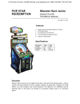
Raptor Capture consists of a lighted Dinosaur panel with a gun. The player console has a
gun for shooting, two numeric displays for game play, speakers for sound effects, two
coin acceptors, and a ticket dispenser for winners. The objective is to skillfully shoot the
ball into the colored dinosaur hoops or cups to obtain the highest point values.
TABLE OF CONTENTS
FEATURES................................................................................................................................................... 1
SPECIFICATIONS ...................................................................................................................................... 1
OVERVIEW ................................................................................................................................................. 1
TABLE OF CONTENTS ............................................................................................................................. 2
GAME PLAY................................................................................................................................................ 4
GAME OPERATOR OPTIONS ................................................................................................................. 5
MAINTENANCE MODE BUTTONS ................................................................................................................. 5
GOING INTO MAINTENANCE MODE ....................................................................................................... 5
Viewing the Statistical Information ........................................................................................................ 5
Changing or Viewing Miscellaneous Settings ........................................................................................ 6
Resetting the Statistics ............................................................................................................................ 6
Running the Diagnostics......................................................................................................................... 6
Changing or Viewing the Playing Field Points ...................................................................................... 7
Changing or Viewing Jackpot Points ..................................................................................................... 7
Changing or Viewing Hoop Points......................................................................................................... 7
Changing or Viewing Clock Face Points ............................................................................................... 8
APPENDIX A INPUT/OUTPUT SIGNALS .............................................................................................. 9
CPU AUXILIARY INPUTS ............................................................................................................................. 9
W4 – VTMUX Board P2 To Pushbuttons & Misc Switches.................................................................... 9
W7 – VTMUX Board P3 To Pushbutton Switches .................................................................................. 9
W90 – VTMUX Board P4 To Opto Board #1 P9.................................................................................. 10
W91 – VTMUX Board P5 to Opto Board #2 P9................................................................................... 10
W95 – VTMUX Board P11 to Opto Board #3 P9................................................................................. 11
W96 – VTMUX Board P12 To Opto Board #4 P9................................................................................ 11
CPU AUXILIARY OUTPUTS ....................................................................................................................... 12
W6 – VTMUX Board P16 To Misc Panel Lights .................................................................................. 12
W15 – VTMUX Board P17 Clockface Lights 1 - 8 ............................................................................... 13
W16 – VTMUX Board P18 Clockface Lights 9 -12 ............................................................................. 13
W17 – VTMUX Board P22 Hoop Lights .............................................................................................. 14
W18 – VTMUX Board P23 Dinosaur Lights with Jackpot Light.......................................................... 14
W19 – VTMUX Board P24 Playfield Lights 1-8................................................................................... 15
W20 – VTMUX Board P29 Playfield Lights 9-10................................................................................. 15
W26 – VTMUX Board P29 Playfield Lights 9-10................................................................................. 16
W24 - VTMUX Board P25 to Small Display ....................................................................................... 16
W25 - VTMUX Board P26 to Small Display ....................................................................................... 16
APPENDIX B WIRING DIAGRAMS...................................................................................................... 17
Diagram 1 – Top Level Interconnect Diagram .................................................................................... 17
Diagram 2 – Top Level Interconnect Diagram 2/4 .............................................................................. 18
Diagram 3 – Top Level Interconnect Diagram 3/4 .............................................................................. 18
Diagram 4 – Top Level Interconnect Diagram 4/4 .............................................................................. 19
Diagram 5 – Functional Components .................................................................................................. 19
Diagram 6 - Playfield Layout............................................................................................................... 20
Figure 1 – W1 (13.7 VDC Power Supply to 8051 VTMux Board P43) ............................................... 20
2
Figure 2 – W2 (13.7 VDC Power Supply to 8051 VTMux Board P19) ............................................... 20
Figure 3 -W3 (13.7 VDC Power Supply and Chassis Ground) ............................................................ 21
Figure 4 - W4 (to Maintenance mode and coin acceptor Switches) ..................................................... 21
Figure 5 - W5 (VTMux Board P30 to AC relays and Tickets Low LED) .................................... 21
Figure 6 - W6 - (VTMux Board P16 to miscellaneous panel lights) .......................................... 22
Figure 7 – W7 (miscellaneous panel Inputs to VTMUX P3)........................................................ 22
Figure 8 - W10 (VTMux Board P4 to Opto Board #1 P9) ............................................................ 23
Figure 9 - W11 (VTMux Board P4 to Opto Board #2 P9) ............................................................ 23
Figure 10 - W12 (VTMux Board P5 to Opto Board #2 P9) .......................................................... 24
Figure 11 - W11 (VTMux Board P11 to Opto Board #3 P9) ........................................................ 24
Figure 12 - W13 (VTMux Board P6 to Opto Board #4 P9) .......................................................... 25
Figure 13 - TARGET SENSORS 1-8..................................................................................................... 25
Figure 14 – Target Sensor 9 –10.......................................................................................................... 26
Figure 15 – Target Sensor 17 - 24........................................................................................................ 26
Figure 16 – Miscellaneous sensor Inputs ...................................................................................... 27
Figure 17 - W15, W16, W17, W18 (VTMux Board P17, P18, P22, P23 to Clockface and Dinosaur
Jackpot Lights) ..................................................................................................................................... 28
Figure 18 - W19, W20, 26 (VTMux Board P24, P29, P31 to Playfield and Arrow Lights).................. 29
Figure 19 - W21 (VTMux Board P28 to Ticket Dispenser) .................................................................. 30
Figure 20 - W23 (VTMux Board P25 to Small 4-Digit Display #1) ..................................................... 30
W24 (VTMux Board P26 to Small 4-Digit Display #2) ........................................................................ 30
Figure 21 - W8 (VTMux Board J1 to Loudspeaker) ............................................................................. 31
Figure 22 - W25 (VTMux Board P1 to chassis ground)....................................................................... 31
APPENDIX C POWER SUPPLIES CONNECTION ............................................................................. 32
W10 (13.7 VDC Power Supply #1 to 8051 VTMux Board P19) ........................................................... 32
W11 (13.7 VDC Power Supply #2 to 8051 VTMux Board P43) ........................................................... 32
W13 (13.7 VDC Power Supplies Ground Interconnect)....................................................................... 32
APPENDIX D PROGRAMMABLE OPTIONS WITH DEFAULTS.................................................... 33
GAME PLAY PROGRAMMING TABLE ......................................................................................................... 33
Game Play Programming Table (Continued)....................................................................................... 34
APPENDIX E REPLACEMENT PARTS................................................................................................ 35
APPENDIX E REPLACEMENT PARTS CONTINUED ....................................................................................... 36
APPENDIX E REPLACEMENT PARTS CONTINUED ....................................................................................... 37
APPENDIX F.............................................................................................................................................. 39
Technical Assistance ............................................................................................................................ 39
Problems and Possible Resolutions.................................................................................................................... 39
Contacting Customer Service ............................................................................................................................ 40
FIVE STAR REDEMPTION .................................................................................................................... 40
ADDRESS AND TELEPHONE NUMBERS ....................................................................................................... 40
3
Game Play
Raptor Capture offers very fast and interesting play with many different strategies for
maximizing points.
The objective is to skillfully shoot the ball into a cup, a stationary or swinging hoop to
obtain points. The player can obtain jackpot points when they have landed or gone
through a specific combination of dinosaur colors.
Tickets may be dispensed during or after game play, and Jackpots are only awarded at the
game end.
4
Game Operator Options
Maintenance Mode allows the Game Operator the option of programming the Game by
entering data through the Control Panel, which is located on the game’s cabinet. This
mode includes viewing the game’s statistical data, running diagnostics, and changing
game play values.
MAINTENANCE MODE BUTTONS
Step Number
Data Value
CREDIT/BALLS
TICKETS/POINTS
Previous Step
Next Step
Increase Data Value
Decrease Data
Value
BALL 1
BALL 2
CALL ATTENDANT
GAME OVER
GOING INTO MAINTENANCE MODE
Pressing the Maintenance Mode button for ½ second or greater allows the operator to go
into Maintenance Mode. The operator can view, run diagnostics or change games play
values. Pressing this button a second time allows the operator to exit.
VIEWING THE STATISTICAL INFORMATION
Pressing the Game 1 Button will decrement the Step Number, and pressing the Game 2
Button will increase the Step Number.
STEP #
0
1
DESCRIPTION
Number of Coins Taken In (Lifetime)
Number of Coins Taken In (Since Last Reset)
5
CHANGING OR VIEWING MISCELLANEOUS SETTINGS
Press Call Attendant button to increase the value, or Press the Game Over button to
decrease the value.
STEP #
10
11
12
13
14
15
16
17
18
19
20
21
22
23
24
DESCRIPTION
Number of Coins Required to Play Game 1
Number of Coins Required to play Game 2
Number of Coins Required to Play Game 3
Number of Balls for Game 1
Number of Balls for Game 2
Number of Balls for Game 3
Maximum Number of Balls Allowed Per Game
Number of Seconds Attraction Audio is On Per cycle
Number of Seconds Attraction Audio is Off per Cycle
Maximum Number of tickets that will dispense before calling Attendant
Ticket Dispensed After Last Ball or Dispense Tickets after Shooting Ball
Number of Seconds Before Returning to Attraction After Game Over
Number of Seconds Between Loading Balls During Attraction
The Spinner Speed in RPM’s
The Spinner Percentage
RESETTING THE STATISTICS
Pressing the Call Attendant button will execute the reset.
STEP #
30
DESCRIPTION
Reset Statistics
RUNNING THE DIAGNOSTICS
Pressing the Game 1 Button will decrement the Step Number, and pressing the Game 2
Button will increase the Step Number.
STEP #
31
DESCRIPTION
Display the Value and Light Associated for the sensor that is blocked
Press the flashing Call Attendant button to execute each diagnostic.
32
33
34
35
Status of Ramp full, Gun loaded, Tickets lows, and tickets out sensors
Dispense Tickets
Load a ball by rotating the turntable.
Control Trough Gate Motor and Display Status of the Trough sensor.
6
CHANGING OR VIEWING THE PLAYING FIELD POINTS
Press Call Attendant button to increase the value, or Press the Game Over button to
decrease the value.
STEP #
40
41
42
43
44
45
46
47
48
49
DESCRIPTION
Points for Green Paw (Y1)
Points for Pink Paw (P1)
Points for Orange Paw (O1)
Points for Yellow Paw (Y1)
Points for Red Paw (R1)
Points for Cave #1
Points for Hole #1
Points for Hole #2
Points for Cave #2
Points for Volcano
CHANGING OR VIEWING JACKPOT POINTS
Press Call Attendant button to increase the value, or Press the Game Over button to
decrease the value.
STEP #
50
51
52
53
DESCRIPTION
Jackpot #1 Points
Jackpot #2 Points
Jackpot #3 Points
Jackpot #4 Points
CHANGING OR VIEWING HOOP POINTS
Press Call Attendant button to increase the value, or Press the Game Over button to
decrease the value.
STEP #
54
55
56
57
58
DESCRIPTION
Points for Hoop #1
Points for Hoop #2
Points for Hoop #3
Points for Hoop #4
Points for Hoop #5
7
CHANGING OR VIEWING CLOCK FACE POINTS
Press Call Attendant button to increase the value, or Press the Game Over button to
decrease the value.
STEP #
60
61
62
63
64
65
66
67
68
69
70
71
DESCRIPTION
Points for 01:00 O’clock Position
Points for 02:00 O’clock Position
Points for 03:00 O’clock Position
Points for 04:00 O’clock Position
Points for 05:00 O’clock Position
Points for 06:00 O’clock Position
Points for 07:00 O’clock Position
Points for 08:00 O’clock Position
Points for 09:00 O’clock Position
Points for10:00 O’clock Position
Points for11:00 O’clock Position
Points for12:00 O’clock Position
8
Appendix A Input/Output Signals
CPU AUXILIARY INPUTS
W4 – VTMUX BOARD P2 TO PUSHBUTTONS & MISC SWITCHES
Control Panel Output
Wire #
Auxiliary Inputs
To VTMUX
Board
Location
NOT USED
GROUND
CONNECTOR KEY
CONNECTOR KEY
MAINTENANCE MODE BUTTON
TILT SWITCH
COIN ACCEPTOR
NOT USED
OPEN DOOR SWITCH
NOT USED
NOT USED
NOT USED
1
2
3
4
5
6
7
8
9
10
11
12
V+
GROUND
KEY
KEY
IN 1
IN 2
IN 3
IN 4
IN 5
IN 6
IN 7
IN 8
JP2 PIN 1
JP2 PIN 2
JP2 PIN 3
JP2 PIN 4
JP2 PIN 5
JP2 PIN 6
JP2 PIN 7
JP2 PIN 8
JP2 PIN 9
JP2 PIN 10
JP2 PIN 11
JP2 PIN 12
W7 – VTMUX BOARD P3 TO PUSHBUTTON SWITCHES
Control Panel Outputs
Wire #
Auxiliary Inputs
To VTMUX
Board
Location
NOT USED
GROUND
CONNECTOR KEY
START BUTTON #1
CONNECTOR KEY
START BUTTON # 2
START BUTTON # 3
NOT USED
NOT USED
NOT USED
GAME OVER BUTTON
CALL ATTENDANT BUTTON
1
2
3
4
5
6
7
8
9
10
11
12
V+
GROUND
KEY
IN 9
KEY
IN 10
IN 11
IN 12
IN 13
IN 14
IN 15
IN 16
9
JP3 PIN 1
JP3 PIN 2
JP3 PIN 3
JP3 PIN 4
JP3 PIN 5
JP3 PIN 6
JP3 PIN 7
JP3 PIN 8
JP3 PIN 9
JP3 PIN 10
JP3 PIN 11
JP3 PIN 12
W90 – VTMUX BOARD P4 TO OPTO BOARD #1 P9
Control Panel Outputs
Wire #
Auxiliary Inputs
12V
GROUND
CONNECTOR KEY
SENSOR CUP # 1
SENSOR CUP #2
CONNECTOR KEY
SENSOR CUP #3
SENSOR CUP #4
SENSOR CUP #5
SENSOR CUP #6
SENSOR CUP #7
SENSOR CUP #8
1
2
3
4
5
6
7
8
9
10
11
12
V+
GROUND
KEY
IN 17
IN 18
KEY
IN 19
IN 20
IN 21
IN 22
IN 23
IN 24
W91 – VTMUX BOARD P5 TO OPTO BOARD #2 P9
Inputs
Wire #
Auxiliary Inputs
To VTMUX
Board
Location
JP4 PIN 1
JP4 PIN 2
JP4 PIN 3
JP4 PIN 4
JP4 PIN 5
JP4 PIN 6
JP4 PIN 7
JP4 PIN 8
JP4 PIN 9
JP4 PIN 10
JP4 PIN 11
JP4 PIN 12
To VTMUX
Board
Location
12V
1
V+
JP5 PIN 1
GROUND
CONNECTOR KEY
SENSOR CUP #9
SENSOR CUP #10
SENSOR CUP #11
CONNECTOR KEY
SENSOR CUP #12
SENSOR CUP #12
SENSOR CUP #14
SENSOR CUP #15
SENSOR CUP #16
2
3
4
5
6
7
8
9
10
11
12
GROUND
KEY
IN 25
IN 26
IN 27
KEY
IN 28
IN 29
IN 30
IN 31
IN 32
JP5 PIN 2
JP5 PIN 3
JP5 PIN 4
JP5 PIN 5
JP5 PIN 6
JP5 PIN 7
JP5 PIN 8
JP5 PIN 9
JP5 PIN 10
JP5 PIN 11
JP5 PIN 12
10
W95 – VTMUX BOARD P11 TO OPTO BOARD #3 P9
Inputs
Wire #
Auxiliary Inputs
To VTMUX
Board
Location
12V
1
V+
JP11 PIN 1
GROUND
CONNECTOR KEY
SENSOR HOOP #17
SENSOR HOOP #18
SENSOR HOOP #19
SENSOR HOOP #20
SENSOR HOOP #21
SENSOR HOOP #22
SENSOR HOOP #23
CONNECTOR KEY
SENSOR HOOP #24
2
3
4
5
6
7
8
9
10
11
12
GROUND
KEY
IN 57
IN 58
IN 59
IN 60
IN 61
IN 62
IN 63
KEY
IN 64
JP11 PIN 2
JP11 PIN 3
JP11 PIN 4
JP11 PIN 5
JP11 PIN 6
JP11 PIN 7
JP11 PIN 8
JP11 PIN 9
JP11 PIN 10
JP11 PIN 11
JP11 PIN 12
W96 – VTMUX BOARD P12 TO OPTO BOARD #4 P9
Inputs
Wire #
Auxiliary Inputs
12V
GROUND
CONNECTOR KEY
BALL PRELOADED SENSOR
GUN & TROUGH SENSOR
TICKETS LOW SENSOR
TICKETS OUT SENSOR
RAMP FULL SENSOR
NOT USED
NOT USED
NOT USED
CONNECTOR KEY
1
2
3
4
5
6
7
8
6
10
11
12
V+
GROUND
KEY
IN 65
IN 66
IN 67
IN 68
IN 69
IN 70
IN 71
IN 72
KEY
11
To VTMUX
Board
Location
JP12 PIN 1
JP12 PIN 2
JP12 PIN 3
JP12 PIN 4
JP12 PIN 5
JP12 PIN 6
JP12 PIN 7
JP12 PIN 8
JP12 PIN 9
JP12 PIN 10
JP12 PIN 11
JP12 PIN 12
CPU AUXILIARY OUTPUTS
W6 – VTMUX BOARD P16 TO MISC PANEL LIGHTS
Outputs
Wire #
Auxiliary Outputs
CONNECTOR KEY
GROUND
GROUND
CONNECTOR KEY
START #1 BUTTON LIGHT
START #2 BUTTON LIGHT
START # 3 BUTTON LIGHT
NOT USED
NOT USED
NOT USED
GAME OVER LIGHT
CALL ATTENDANT LIGHT
1
2
3
4
5
6
7
8
6
10
11
12
KEY
GROUND
GROUND
KEY
OUT 1
OUT 2
OUT 3
OUT 4
OUT 5
OUT 6
OUT 7
OUT 8
12
To VTMUX
Board
Location
JP16 PIN 1
JP16 PIN 2
JP16 PIN 3
JP16 PIN 4
JP16 PIN 5
JP16 PIN 6
JP16 PIN 7
JP16 PIN 8
JP16 PIN 9
JP16 PIN 10
JP16 PIN 11
JP16 PIN 12
W15 – VTMUX BOARD P17 CLOCKFACE LIGHTS 1 - 8
Outputs
Wire #
Auxiliary Outputs
To VTMUX
Board
Location
CONNECTOR KEY
GROUND
GROUND
CLOCKFACE #1
CONNECTOR KEY
CLOCKFACE #2
CLOCKFACE #3
CLOCKFACE #4
CLOCKFACE #5
CLOCKFACE #6
CLOCKFACE #7
CLOCKFACE #8
1
2
3
4
5
6
7
8
6
10
11
12
KEY
GROUND
GROUND
OUT 9
KEY
OUT 10
OUT 11
OUT 12
OUT 13
OUT 14
OUT 15
OUT 16
JP17 PIN 1
JP17 PIN 2
JP17 PIN 3
JP17 PIN 4
JP17 PIN 5
JP17 PIN 6
JP17 PIN 7
JP17 PIN 8
JP17 PIN 9
JP17PIN 10
JP17 PIN 11
JP17 PIN 12
W16 – VTMUX BOARD P18 CLOCKFACE LIGHTS 9 -12
Outputs
Wire #
Auxiliary Outputs
To VTMUX
Board
Location
CONNECTOR KEY
GROUND
GROUND
CLOCKFACE #9
CLOCKFACE #10
CONNECTOR KEY
CLOCKFACE #11
CLOCKFACE #12
NOT USED
NOT USED
NOT USED
NOT USED
1
2
3
4
5
6
7
8
6
10
11
12
KEY
GROUND
GROUND
OUT 17
OUT 18
KEY
OUT 19
OUT 20
OUT 21
OUT 22
OUT 23
OUT 24
13
JP18 PIN 1
JP18 PIN 2
JP18 PIN 3
JP18 PIN 4
JP18 PIN 5
JP18 PIN 6
JP18 PIN 7
JP18 PIN 8
JP18 PIN 9
JP18 PIN 10
JP18 PIN 11
JP18 PIN 12
W17 – VTMUX BOARD P22 HOOP LIGHTS
Outputs
Wire #
Auxiliary Outputs
CONNECTOR KEY
GROUND
GROUND
HOOP #1
HOOP #2
HOOP #3
CONNECTOR KEY
HOOP #4
HOOP #5
HOOP #6
NOT USED
NOT USED
1
2
3
4
5
6
7
8
6
10
11
12
KEY
GROUND
GROUND
OUT 25
OUT 26
OUT 27
KEY
OUT 28
OUT 29
OUT 30
OUT 31
OUT 32
To VTMUX
Board
Location
JP22 PIN 1
JP22 PIN 2
JP22 PIN 3
JP22 PIN 4
JP22 PIN 5
JP22 PIN 6
JP22 PIN 7
JP22 PIN 8
JP22 PIN 9
JP22 PIN 10
JP22 PIN 11
JP22 PIN 12
W18 – VTMUX BOARD P23 DINOSAUR LIGHTS WITH JACKPOT LIGHT
Outputs
Wire #
Auxiliary Outputs
To VTMUX
Board
Location
CONNECTOR KEY
GROUND
GROUND
DINO YELLOW
DINO ORANGE
DINO PINK
DINO GREEN
CONNECTOR KEY
DINO RED
NOT USED
NOT USED
SUPER JACKPOT
1
2
3
4
5
6
7
8
6
10
11
12
KEY
GROUND
GROUND
OUT 33
OUT 34
OUT 35
OUT 36
KEY
OUT 37
OUT 38
OUT 39
OUT 40
14
JP23 PIN 1
JP23 PIN 2
JP23 PIN 3
JP23 PIN 4
JP23 PIN 5
JP23 PIN 6
JP23 PIN 7
JP23 PIN 8
JP23 PIN 9
JP23 PIN 10
JP23 PIN 11
JP23 PIN 12
W19 – VTMUX BOARD P24 PLAYFIELD LIGHTS 1-8
Inputs
Wire #
Auxiliary Inputs
CONNECTOR KEY
GROUND
GROUND
PLAYFIELD #1
PLAYFIELD #2
PLAYFIELD #3
PLAYFIELD #4
PLAYFIELD #5
CONNECTOR KEY
PLAYFIELD #6
PLAYFIELD #7
PLAYFIELD #8
1
2
3
4
5
6
7
8
9
10
11
12
KEY
GROUND
GROUND
OUT 41
OUT 42
OUT 43
OUT 44
OUT 45
KEY
OUT 46
OUT 47
OUT 48
To VTMUX
Board
Location
JP24 PIN 1
JP24 PIN 2
JP24 PIN 3
JP24PIN 4
JP24 PIN 5
JP24 PIN 6
JP24 PIN 7
JP24 PIN 8
JP24 PIN 9
JP24 PIN 10
JP24 PIN 11
JP24 PIN 12
W20 – VTMUX BOARD P29 PLAYFIELD LIGHTS 9-10
Inputs
Wire #
Auxiliary Inputs
To VTMUX
Board
Location
CONNECTOR KEY
GROUND
GROUND
PLAYFIELD #9
PLAYFIELD #10
NOT USED
NOT USED
NOT USED
NOT USED
CONNECTOR KEY
NOT USED
NOT USED
1
2
3
4
5
6
7
8
9
10
11
12
KEY
GROUND
GROUND
OUT 49
OUT 50
OUT 51
OUT 52
OUT 53
OUT 54
KEY
OUT 55
OUT 56
15
JP29 PIN 1
JP29 PIN 2
JP29 PIN 3
JP29PIN 4
JP29 PIN 5
JP29 PIN 6
JP29 PIN 7
JP29 PIN 8
JP29 PIN 9
JP29 PIN 10
JP29 PIN 11
JP29 PIN 12
W26 – VTMUX BOARD P29 PLAYFIELD LIGHTS 9-10
Inputs
Wire #
Auxiliary Inputs
To VTMUX
Board
Location
CONNECTOR KEY
GROUND
GROUND
PLAYFIELD #9
PLAYFIELD #10
NOT USED
NOT USED
NOT USED
NOT USED
CONNECTOR KEY
NOT USED
NOT USED
1
2
3
4
5
6
7
8
9
10
11
12
KEY
GROUND
GROUND
OUT 49
OUT 50
OUT 51
OUT 52
OUT 53
OUT 54
KEY
OUT 55
OUT 56
JP29 PIN 1
JP29 PIN 2
JP29 PIN 3
JP29PIN 4
JP29 PIN 5
JP29 PIN 6
JP29 PIN 7
JP29 PIN 8
JP29 PIN 9
JP29 PIN 10
JP29 PIN 11
JP29 PIN 12
W24 - VTMUX BOARD P25 TO SMALL DISPLAY
Outputs
Display Outputs
From CPU Board
Location
NOT CONNECTED
GROUND
SMALL DISPLAY ENABLE
DISP 0E1
SMALL DISPLAY CLK
DISP CLK
SMALL DISPLAY NOT CONNECTED
V+
SMALL DISPLAY VPP & VLED
VCC
SMALL DISPLAY NOT CONNECTED
DISP STB1
SMALL DISPLAY DATA
DISP DATA1
GROUND
GROUND
JP25-1
JP25-2
JP25-3
JP25-4
JP25-5
JP25-6
JP25-7
JP25-8
W25 - VTMUX BOARD P26 TO SMALL DISPLAY
NOT CONNECTED
GROUND
SMALL DISPLAY ENABLE
DISP 0E2
SMALL DISPLAY CLK
DISP CLK
SMALL DISPLAY NOT CONNECTED
V+
SMALL DISPLAY VPP & VLED
VCC
SMALL DISPLAY NOT CONNECTED
DISP STB2
SMALL DISPLAY DATA
DISP DATA2
GROUND
GROUND
16
JP26-1
JP26-2
JP26-3
JP26-4
JP26-5
JP26-6
JP26-7
JP26-8
Appendix B Wiring Diagrams
to LV ower
TOP LEVEL INTERCONNECT DIAGRAM 1/4
Clockface light outputs
Hoop light outputs
Dinosaur/jackpot light outputs
Arrow light outputs
Miscellaneous Sensor Inputs from sheet 4/4
Playfield light outputs
Cup and Hoop Sensor
Inputs from sheet 3/4
Ticket Meter
Ticket
Dispenser
Motor
Cup Sensor Inputs from sheet 2/4
W22
W90
W95
W91
P4
P5
W96
P11
P12
W15
W16
P17
P18
W17
W18
P22
W19
P23
W20
P24
Ticket
Dispenser
Assembly
W26
P29
P31
P3
P28
8051 VTMux Board
(Note: connectors not show in actual locations on PCB)
Loadspeaker
W8
P25
P3
W23
Ribbon Cable
J1
P26
W25
P2
Ticket Dispenser
Control Board
W21
W24
Ribbon Cable
P1
P3
W7
P16
W6
P30
W5
P2
P19
P43
W4
Small 4-digit Display #1
Pushbutton Inputs
Small 4-digit Display #2
Miscellaneous
and
PushbuttonLights
Fan Motor
W1
W2
120 VAC
W3
Swing Motor
120 VAC
13.7 VDC Power
Supply #2
13.7 VDC Power
Supply #1
(Dirty P/S)
120 VAC
120 VAC
Turntable Motor
Trough Gate Motor
Ticket Counter
Coin acceptor contact and program mode
pushbutton
Tickets Low LED
DIAGRAM 1 – TOP LEVEL INTERCONNECT DIAGRAM
17
Note: GND return from Jackpot
Dinosaur and Tram lights go
dirrectly to ground terminal of
Power Supply #1 (Dirty P/S)
APPENDIX B WIRING DIAGRAMS
TOP LEVEL INTERCONNECT DIAGRAM 2/4
Cup Sensors #1-8
CSNS1-1
(yellow 1)
W30
CSNS1-2
(yellow 2)
W31
P1
CSNS1-3
(orange 1)
W32
P2
CSNS1-4
(pink 1)
W33
P3
CSNS1-5
(green 1)
W34
P4
Cup Sensors #9-10
CSNS1-6
(red 1)
W35
P5
CSNS1-7
(no color 1)
W36
P6
CSNS1-8
(no color 2)
CSNS2-1
CSNS2-2
(no color 3) (no color 4)
W37
P7
W38
P8
W39
P1
P2
P3
P4
P5
Opto Board #1
Opto Board #2
P9
P9
W90
P6
W91
Cup Sensor Inputs to sheet 1/4
Cup Sensor Inputs to sheet 1/4
DIAGRAM 2 – TOP LEVEL INTERCONNECT DIAGRAM 2/4
TOP LEVEL INTERCONNECT DIAGRAM 3/4
Hoop Sensors #1-6
HSNS3-1
(yellow)
W70
HSNS3-2
(orange)
W71
P1
HSNS3-3
(pink)
W72
P2
HSNS3-4
(green)
W73
P3
HSNS3-5
(red)
W74
P4
HSNS3-6
(swing)
W75
P5
P6
Opto Board #3
P9
W95
Hoop Sensor Inputs to sheet 1/4
DIAGRAM 3 – TOP LEVEL INTERCONNECT DIAGRAM 3/4
18
P7
P8
WIRING DIAGRAMS APPENDIX B
TOP LEVEL INTERCONNECT DIAGRAM 4/4
Miscellaneous Sensors
GTSNS4-2 TLSNS4-1 TOSNS4-2 RFSNS4-3
W79
P1
W80
P2
W81
P3
W82
P4
P5
P6
P7
P8
GTSNS
TLSNS
TOSNS
RFSNS
Opto Board #4
Gun and Trough Sens
Tickets Low Sensor
Tickets Out Sensor
Ramp Full Sensor
P9
W96
Ball Control Sensor Inputs to sheet 1/4
DIAGRAM 4 – TOP LEVEL INTERCONNECT DIAGRAM 4/4
lighted
hoop #2
lighted
hoop #3
CF
10
red
dino light
(#5)
lighted
hoop #4
lighted
hoop #5
Arrow #4
lighted
hoop #1
green
dino light
(#4)
Arrow #3
pink
dino light
(#3)
Arrow #2
orange
dino light
(#2)
Arrow #1
yellow
dino light
(#1)
CF
11
CF
12
CF
01
CF
02
CF
09
12 clockface
lights
CF
03
CF
08
CF
07
CF
06
CF
05
CF
04
Lighted Pushbuttons
Lighted Pushbutton
(button input only used
in program mode)
CALL
ATTN
START
$0.25
START
$0.50
START
$1.00
GAME
OVER
Credits
Ticket Dispenser
Balls
Small 4-digit
7-segment Displays
Coin Acceptors
TICKETS LOW
(Red LED)
$0.25 = 1 BALL
$0.50 = 2 BALLS
$1.00 = 5 BALLS
SHOOT
Score
DIAGRAM 5 – FUNCTIONAL COMPONENTS
19
WIRING DIAGRAMS APPENDIX B
PLAYING FIELD
VOLCANO
GREEN
PAW
PINK
PAW
RED
PAW
Legend:
GREEN PAW
PINK PAW
ORANGE PAW
YELLOW PAW
RED PAW
CAVE #1
HOLE #1
HOLE #2
CAVE #2
VOLCANO
opto board #1 P1
opto board #1 P2
opto board #1 P3
opto board #1 P4
opto board #1 P5
opto board #1 P6
opto board #1 P7
opto board #1 P8
opto board #2 P1
opto board #2 P2
ORANGE
PAW
YELLOW
PAW
HOLE
#1
CAVE #1
CAVE #2
HOLE
#2
DIAGRAM 6 - PLAYFIELD LAYOUT
W1
Ground Terminal of Power
Supply #1 (Dirty P/S)
BLK
4
BLK
3
RED
2
RED
Positive Terminal of Power
Supply #1 (Dirty P/S)
1
16 AWG Wire
(Plugs into VTMux Board P43)
Mate-N-Loc plug
Amp 350779-1
Molex 50-84-1045
Mate-N-Loc contacts, socket, 14-20 AWG
Amp 350550
Molex 02-08-1002
FIGURE 1 – W1 (13.7 VDC POWER SUPPLY TO 8051 VTMUX BOARD P43)
W2
(Ring lugs fasten to
binding posts on 13.7
VDC power supply-logic power)
(Plugs into VTMux Board P19)
BLK
2
RED
1
16 AWG Wire
Mate-N-Loc plug
Amp 350777-1
Molex 50-84-1025
Mate-N-Loc contacts, socket, 14-20 AWG
Amp 350550
Molex 02-08-1002
FIGURE 2 – W2 (13.7 VDC POWER SUPPLY TO 8051 VTMUX BOARD P19)
20
WIRING DIAGRAMS APPENDIX B
W3
Ground terminal of
Power Supply #1
(Dirty P/S)
Unpainted surface of
game chassis
BLK
16 AWG Wire
(W3 connects the ground terminals of both
the 13.7 VDC power supplies together and
to an unpainted surface of game chassis)
Ground terminal of
Power Supply #2
FIGURE 3 -W3 (13.7 VDC POWER SUPPLY AND CHASSIS GROUND)
W4
Top View
Plugs into
VTMux Board P2
1
2
key
key
5
6
7
8
9
10
11
12
All Wire 22 AW G
Ground
Maintenance Mode
B tt
Coin Input
Coin Acceptor #1
Coin Acceptor #2
Amp 1-640620-2 or
Panduit CE100F22-12-C
(for 22 AW G Wire)
NEG
End View
+12VDC
(from Power Supply #1)
POS
Coin Meter
FIGURE 4 - W4 (TO MAINTENANCE MODE AND COIN ACCEPTOR
SWITCHES)
Top View
Plugs into
VTMux Board P30
Amp 1-640620-2 or
Panduit CE100F22-12-C
(for 22 AWG Wire)
W5
key
2
3
4
5
6
7
8
9
10
key
12
390 Ohm, 1/2 W
Tickets Low
LED
Turntable
Direction Relay
End View
All Wire 22 AWG
Happy
Face
Counter
Trough
Gate
Motor
DC
Motor
DC
Relay
Turntable Motor
16V back-toback Zener
Diodes
NO
NC
Turntable
Motor
DC
Motor
DC
Motor
NO
NC
AC
Motor
Fan
Motor
AC
Motor
Swing
Motor
Reversable
Turntable Option
120 VAC
Standard Non-reversable
Turntable
120 VAC
(Wire one way or the other, depending
upon whether or not the reversable
turntable option is required)
FIGURE 5 - W5 (VTMUX BOARD P30 TO AC RELAYS AND TICKETS LOW LED)
21
WIRING DIAGRAMS APPENDIX B
W6
Top View
Plugs into
VTMux Board P16
key
2
3
key
5
6
7
8
9
10
11
12
All Wire 22 AWG
Ground
Start Button Light SBL1
Start Button Light SBL2
Start Button Light SBL3
These wires solder
to Control Panel
Lights
Game Over Light GOL
Call Attendent Light CAL
Amp 1-640620-2 or
Panduit CE100F22-12-C
(for 22 AWG Wire)
End View
FIGURE 6 - W6 - (VTMUX BOARD P16 TO MISCELLANEOUS PANEL LIGHTS)
W7
Top View
Plugs into
VTMux Board P3
1
2
key
4
key
6
7
8
9
10
11
12
All Wire 22 AWG
Ground
Start Button Contact SBC1
Start Button Contact SBC2
Start Button Contact SBC3
These wires solder to
Control Panel
Pushbutton Switch
Contacts
Game Over Contact GOC
Call Attn Contact CAC
Amp 1-640620-2 or
Panduit CE100F22-12-C
(for 22 AWG Wire)
End View
FIGURE 7 – W7 (MISCELLANEOUS PANEL INPUTS TO VTMUX P3)
22
WIRING DIAGRAMS APPENDIX B
W10
Plugs into
VTMux Board P4
Top View
Top View
1
2
key
4
5
key
7
8
9
10
11
12
1
2
key
4
5
key
7
8
9
10
11
12
Plugs into
Opto Board #1 P9
All Wire 22 AWG
End View
End View
FIGURE 8 - W10 (VTMUX BOARD P4 TO OPTO BOARD #1 P9)
W11
Plugs into
VTMux Board P5
Top View
Top View
1
2
key
4
5
6
key
8
9
10
11
12
1
2
key
4
5
key
7
8
9
10
11
12
Plugs into
Opto Board #2 P9
All Wire 22 AWG
End View
End View
FIGURE 9 - W11 (VTMUX BOARD P4 TO OPTO BOARD #2 P9)
23
WIRING DIAGRAMS APPENDIX B
W11
Plugs into
VTMux Board P5
Top View
Top View
1
2
key
4
5
6
key
8
9
10
11
12
1
2
key
4
5
key
7
8
9
10
11
12
Plugs into
Opto Board #2 P9
All Wire 22 AWG
End View
End View
FIGURE 10 - W12 (VTMUX BOARD P5 TO OPTO BOARD #2 P9)
W95
Plugs into
VTMux Board P11
Top View
Top View
1
2
key
4
5
6
7
8
9
10
key
12
1
2
key
4
5
key
7
8
9
10
11
12
Plugs into
Opto Board #3 P9
All Wire 22 AWG
End View
End View
FIGURE 11 - W11 (VTMUX BOARD P11 TO OPTO BOARD #3 P9)
24
WIRING DIAGRAMS APPENDIX B
W96
Top View
Top View
1
2
key
4
5
6
7
8
9
10
11
key
1
2
key
4
5
key
7
8
9
10
11
12
Plugs into
VTMux Board P12
Plugs into
Opto Board #4 P9
All Wire 22 AWG
End View
End View
FIGURE 12 - W13 (VTMUX BOARD P6 TO OPTO BOARD #4 P9)
CSNS1-1
CSNS1-2
CSNS1-3
CSNS1-4
All Wire 22 AWG
A
C
A
C
A
C
A
C
K
E
K
E
K
E
K
E
Cup Sensor #1
(green paw)
BLK
Cup Sensor #2
(pink paw)
BLK
RED
YEL
BLK
Cup Sensor #3
(orange paw)
BLK
RED
YEL
BLK
Cup Sensor #4
(yellow paw)
BLK
RED
YEL
BLK
BLK
RED
YEL
1 2 3 4
1 2 3 4
1 2 3 4
1 2 3 4
W30
(Plugs into P1 of Opto Board #1)
W31
(Plugs into P2 of Opto Board #1)
W32
(Plugs into P3 of Opto Board #1)
W33
(Plugs into P4 of Opto Board #1)
CSNS1-5
CSNS1-6
CSNS1-7
CSNS1-8
A
C
A
C
A
C
A
C
K
E
K
E
K
E
K
E
Cup Sensor #5
(red paw)
BLK
BLK
RED
YEL
Cup Sensor #6
(cave #1)
BLK
BLK
RED
YEL
Cup Sensor #7
(hole #1)
BLK
BLK
RED
YEL
Cup Sensor #8
(hole #2)
BLK
BLK
RED
YEL
1 2 3 4
1 2 3 4
1 2 3 4
1 2 3 4
W34
(Plugs into P5 of Opto Board #1)
W35
(Plugs into P6 of Opto Board #1)
W36
(Plugs into P7 of Opto Board #1)
W37
(Plugs into P8 of Opto Board #1)
FIGURE 13 - TARGET SENSORS 1-8
25
4-pin connectors:
Amp 0-640620-4 or
Panduit CE100F22-4-C
(for 22 AWG Wire)
4-pin connectors:
Amp 0-640620-4 or
Panduit CE100F22-4-C
(for 22 AWG Wire)
WIRING DIAGRAMS APPENDIX B
YSNS3-1
YSNS3-2
YSNS3-3
YSNS3-4
All Wire 22 AWG
A
C
A
C
A
C
A
C
K
E
K
E
K
E
K
E
Hoop Sensor #1
(yellow)
BLK
Hoop Sensor #2
(orange)
BLK
RED
BLK
YEL
Hoop Sensor #3
(pink)
BLK
RED
BLK
YEL
Hoop Sensor #4
(green)
BLK
RED
BLK
YEL
BLK
RED
YEL
1 2 3 4
1 2 3 4
1 2 3 4
1 2 3 4
W70
(Plugs into P1 of Opto Board #3)
W71
(Plugs into P2 of Opto Board #3)
W72
(Plugs into P3 of Opto Board #3)
W73
(Plugs into P4 of Opto Board #3)
YSNS3-5
YSNS3-6
A
C
A
C
K
E
K
E
Hoop Sensor #5
(red)
BLK
4-pin connectors:
Amp 0-640620-4 or
Panduit CE100F22-4-C
(for 22 AWG Wire)
Hoop Sensor #6
(swing)
BLK
RED
BLK
YEL
BLK
RED
YEL
4-pin connectors:
Amp 0-640620-4 or
Panduit CE100F22-4-C
(for 22 AWG Wire)
1 2 3 4
1 2 3 4
W74
(Plugs into P5 of Opto Board #3)
W75
(Plugs into P6 of Opto Board #3)
FIGURE 14 – TARGET SENSOR 9 –10
CSNS2-1
CSNS2-2
All Wire 22 AWG
A
C
A
C
K
E
K
E
Cup Sensor #9
(cave #2)
BLK
Cup Sensor #10
(volcano)
BLK
RED
YEL
1
2
3
4
W38
(Plugs into P1 of Opto Board #2)
BLK
BLK
RED
YEL
1
2
3
4-pin connectors:
Amp 0-640620-4 or
Panduit CE100F22-4-C
(for 22 AWG Wire)
4
W39
(Plugs into P2 of Opto Board #2)
4-pin connectors:
Amp 0-640620-4 or
Panduit CE100F22-4-C
(for 22 AWG Wire)
FIGURE 15 – TARGET SENSOR 17 - 24
26
WIRING DIAGRAMS APPENDIX B
GTSNS4-2
TLSNS4-3
TONS4-4
A
C
A
C
A
C
K
E
K
E
K
E
A
C
K
E
All Wire 22 AWG
Gun and
Trough
Sensor
BLK
Tickets Low
Sensor
BLK
RED
YEL
1 2 3 4
W79
(Plugs into P2 of Opto Board #4)
BLK
Tickets Out
Sensor
BLK
RED
YEL
1 2 3 4
W80
(Plugs into P3 of Opto Board #4)
BLK
BLK
RED
YEL
1 2 3 4
W81
(Plugs into P4 of Opto Board #4)
RFSNS4-1
A
C
K
E
A
C
K
E
Ramp Full
Sensor
BLK
BLK
RED
YEL
1 2 3 4
W82
(Plugs into P1 of Opto Board #4)
FIGURE 16 – MISCELLANEOUS SENSOR INPUTS
27
4-pin connectors:
Amp 0-640620-4 or
Panduit CE100F22-4-C
(for 22 AWG Wire)
WIRING DIAGRAMS APPENDIX B
W15
Top View
Plugs into
VTMux Board P17
key
2
3
4
key
6
7
8
9
10
11
12
W16
Top View
All Wire 22 AWG
Clockface #01
Clockface #02
Clockface #03
Clockface #04
Clockface #05
Clockface #06
Clockface #07
Clockface #08
These wires solder
to Clockface #01-08
Lights
Plugs into
VTMux Board
P18
key
2
3
4
5
key
7
8
9
10
11
12
Amp 1-640620-2 or
Panduit CE100F22-12-C
(for 22 AWG Wire)
All Wire 22 AWG
Clockface #09
Clockface #10
Clockface #11
Clockface #12
These wires
solder to
Clockface #09-12
Lights
Amp 1-640620-2 or
Panduit CE100F22-12-C
(for 22 AWG Wire)
End View
End View
GND (light return goes
directly to Low Voltage
Power Supply #1)
Plugs into
VTMux Board
P22
W17
W18
Top View
Top View
key
2
3
4
5
6
key
8
9
10
11
12
All Wire 22 AWG
Hoop #1(yellow)
Hoop #2 (orange)
Hoop #3 (pink)
Hoop #4 (green)
Hoop #5 (red)
Hoop #6 (swing)
These wires
solder to
Hoop #1-6
Lights
Plugs into
VTMux Board
P23
key
2
3
4
5
6
7
key
9
10
11
12
Amp 1-640620-2 or
Panduit CE100F22-12-C
(for 22 AWG Wire)
All Wire 22 AWG
Dino (yellow)
Dino (orange)
Dino (pink)
Dino (green)
Dino (red)
These wires
solder to
Jackpot
Lights
Super Jackpot
Amp 1-640620-2 or
Panduit CE100F22-12-C
(for 22 AWG Wire)
End View
End View
FIGURE 17 - W15, W16, W17, W18 (VTMUX BOARD P17, P18, P22, P23 TO
CLOCKFACE AND DINOSAUR JACKPOT LIGHTS)
28
WIRING DIAGRAMS APPENDIX B
W19
Top View
Plugs into
VTMux Board P24
key
2
3
4
5
6
7
8
key
10
11
12
W20
Top View
All Wire 22 AWG
Playfield (green paw)
Playfield (pink paw)
Playfield (orange paw)
Playfield (yellow paw)
Playfield (red paw)
These wires solder
to Playfield #01-08
Lights
Playfield (cave #1)
Playfield (hole #1)
Playfield (hole #2)
Plugs into
VTMux Board
P29
key
2
3
4
5
6
7
8
9
key
11
12
Amp 1-640620-2 or
Panduit CE100F22-12-C
(for 22 AWG Wire)
All Wire 22 AWG
Playfield (cave #2)
Playfield (volcano)
These wires
solder to Playfield
#09-12 Lights
Amp 1-640620-2 or
Panduit CE100F22-12-C
(for 22 AWG Wire)
End View
End View
GND (light return goes
directly to Low Voltage
Power Supply #1)
W26
Top View
Plugs into
VTMux Board
P31
key
2
3
4
5
6
7
8
9
10
11
key
All Wire 22 AWG
Win Right 1
Win Right 2
Jackpot Right 1
Jackpot Right 2
Jackpot Left 1
Jackpot Left 2
Win Left 1
Win Left 2
These wires
solder to Playfield
#09-12 Lights
Amp 1-640620-2 or
Panduit CE100F22-12-C
(for 22 AWG Wire)
End View
FIGURE 18 - W19, W20, 26 (VTMUX BOARD P24, P29, P31 TO PLAYFIELD
AND ARROW LIGHTS)
29
WIRING DIAGRAMS APPENDIX B
W21
All Wire 22 AWG
Top View
Plugs into
VTMux Board P28
1
key
3
4
5
6
Ticket Notch Input #1
1
2
3
4
Ticket Enable Output #1
+12 VDC
+12VDC Ground
Plugs into P3 of Deltronic
Labs, Inc. Control Board DL1275
Receptacle housing,
Molex 03-09-1041
with female contacts
Amp 0-640620-6 or
Panduit CE100F22-6-C
(for 22 AWG Wire)
End View
FIGURE 19 - W21 (VTMUX BOARD P28 TO TICKET DISPENSER)
Pin
Signal
1
Brightness
2
Vpp
3
Clock
4
DATA
5
ENABLE
6
Ground
7
VLED
8
N/A
1
2
3
4
Four Digit Display
Rear View
1
B
l
u
e
B O B
l r l
u a a
e n c
g k
e
B
r
o
w
n
R
e
d
d
O
r
a
n
g
e
Y
e
l
l
o
w
R
e
d
G Y B G
r e r r
e l o a
e l w y
n o n
w
8
1
FIGURE 20 - W23 (VTMUX BOARD P25 TO SMALL 4-DIGIT DISPLAY #1)
W24 (VTMUX BOARD P26 TO SMALL 4-DIGIT DISPLAY #2)
30
APPENDIX B WIRING DIAGRAMS
W8
18 AWG wire
Top View
Plugs into
VTMux Board J1
Audio +
Audio Shield
1
2
3
Load
speaker
Molex 09503031 plug housing
Molex 08520072 crimp contact, 18-20 AWG
End View
FIGURE 21 - W8 (VTMUX BOARD J1 TO LOUDSPEAKER)
Screw to
unpainted surface
of chassis
W25
Plugs into P1 of
VTMux Board
16 AWG Black Wire
Female
Faston Tab
Ring Lug
FIGURE 22 - W25 (VTMUX BOARD P1 TO CHASSIS GROUND)
31
Appendix C Power Supplies Connection
W10 (13.7 VDC POWER SUPPLY #1 TO 8051 VTMUX BOARD P19)
W 10
(Plugs into VTMux Board P19)
(Ring lughs fasten to
binding posts on 13.7
VDC power supply #1-logic power)
BLK
2
RED
1
16 AWG Wire
Mate-N-Loc plug
Amp 350777-1
Molex 50-84-1025
Mate-N-Loc contacts, socket, 14-20 AWG
Amp 350550
Molex 02-08-1002
W11 (13.7 VDC POWER SUPPLY #2 TO 8051 VTMUX BOARD P43)
W 11
BLK
4
BLK
(Ring lughs fasten to
binding posts on 13.7
VDC power supply #2-lights/motors power)
3
RED
2
RED
1
16 AWG Wire
(Plugs into VTMux Board P43)
Mate-N-Loc plug
Amp 350779-1
Molex 50-84-1045
Mate-N-Loc contacts, socket, 14-20 AWG
Amp 350550
Molex 02-08-1002
W13 (13.7 VDC POWER SUPPLIES GROUND INTERCONNECT)
W39
BLK
16 AWG Wire
(W39 connects the two ground terminals of
the two 13.7 VDC power supplies together)
32
Appendix D Programmable Options with Defaults
GAME PLAY PROGRAMMING TABLE
STEP#
0
1
10
11
12
13
14
15
16
17
18
19
20
21
22
23
24
30
31
32
33
34
35
40
41
42
43
44
45
46
47
48
49
PROGRAM OPTION
NUMBER OF COINS TAKEN IN (LIFETIME)
NUMBER OF COINS TAKEN IN (SINCE RESET)
COINS REQUIRED TO PLAY GAME 1
COINS REQUIRED TO PLAY GAME 2
COINS REQUIRED TO PLAY GAME 3
NUMBER OF BALLS FOR GAME 1
NUMBER OF BALLS FOR GAME 2
NUMBER OF BALLS FOR GAME 3
MAXIMUM NUMBER OF BALLS PER GAME
AUDIO ATTRACTION ON TIME
AUDIO ATTRACTION OFF TIME
MAXIMUM TICKETS WITHOUT ATTENDANT
DISPENSE TICKET AFTER OR DURING GAME
NUMBER OF SECONDS BEFORE LEAVING GAME
NUMBER OF SECONDS BETWEEN BALL LOADING
SPINNER SPEED
SPINNER PERCENTAGE
RESET ALL RESETABLE STATISTICS
DISPLAY NUMBER OF SENSOR THAT IS BLOCKED
DISPLAY MISC OPTO SENSOR STATUS
DISPENSE TICKETS
TEST TURNTABLE MOTOR
TEST GUN TROUGH MOTOR
POINTS FOR GREEN PAW (G1)
POINTS FOR PINK PAW (P1)
POINTS FOR ORANGE PAW (O1)
POINTS FOR YELLOW PAW (Y1)
POINTS FOR RED PAW (R1)
POINTS FOR CAVE #1
POINTS FOR HOLE #1
POINTS FOR HOLE #2
POINTS FOR CAVE #2
POINTS FOR VOLCANO
33
TYPE
COINS
COINS
COINS
COINS
COINS
BALLS
BALLS
BALLS
BALLS
SECONDS
SECONDS
TICKETS
BOOL
SECONDS
SECONDS
RPM’S
PERCENT
N/A
N/A
N/A
N/A
N/A
N/A
POINTS
POINTS
POINTS
POINTS
POINTS
POINTS
POINTS
POINTS
POINTS
POINTS
PROGRAMMABLE
NO
NO
YES
YES
YES
YES
YES
YES
YES
YES
YES
YES
YES
YES
YES
YES
YES
NO
N/A
N/A
N/A
N/A
N/A
YES
YES
YES
YES
YES
YES
YES
YES
YES
YES
VALUE
N/A
N/A
1
2
4
1
2
5
5
30
10
500
1
20
15
60
5
N/A
N/A
N/A
N/A
N/A
N/A
10
10
5
5
15
10
1
1
15
100
GAME PLAY PROGRAMMING TABLE (CONTINUED)
50
51
52
53
54
55
56
57
58
60
61
62
63
64
65
66
67
68
69
70
71
JACKPOT #1 POINTS
JACKPOT #2 POINTS
JACKPOT #3 POINTS
JACKPOT #4 POINTS
POINTS FOR HOOP #1
POINTS FOR HOOP #2
POINTS FOR HOOP #3
POINTS FOR HOOP #4
POINTS FOR HOOP #5
CLOCKFACE POINTS FOR 1:00 POSITION
CLOCKFACE POINTS FOR 2:00 POSITION
CLOCKFACE POINTS FOR 3:00 POSITION
CLOCKFACE POINTS FOR 4:00 POSITION
CLOCKFACE POINTS FOR 5:00 POSITION
CLOCKFACE POINTS FOR 6:00 POSITION
CLOCKFACE POINTS FOR 7:00 POSITION
CLOCKFACE POINTS FOR 8:00 POSITION
CLOCKFACE POINTS FOR 9:00 POSITION
CLOCKFACE POINTS FOR 10:00 POSITION
CLOCKFACE POINTS FOR 11:00 POSITION
CLOCKFACE POINTS FOR 12:00 POSITION
POINTS
POINTS
POINTS
POINTS
POINTS
POINTS
POINTS
POINTS
POINTS
POINTS
POINTS
POINTS
POINTS
POINTS
POINTS
POINTS
POINTS
POINTS
POINTS
POINTS
POINTS
34
YES
YES
YES
YES
YES
YES
YES
YES
YES
YES
YES
YES
YES
YES
YES
YES
YES
YES
YES
YES
YES
20
50
100
1000
100
15
500
25
250
10
25
10
5
10
50
10
5
10
25
5
250
Appendix E Replacement Parts
35
APPENDIX E REPLACEMENT PARTS CONTINUED
36
APPENDIX E REPLACEMENT PARTS CONTINUED
37
APPENDIX E REPLACEMENT PARTS CONTINUED
38
Appendix F
TECHNICAL ASSISTANCE
Problems and Possible Resolutions
Symptom
Resolution
Game is not running properly. 1 display is blank,
and the other has zeros.
Check the power supply connected to P41 or P43,
insure that the red LED is illuminated in the back of
Power Supply # 1. If not illuminated replace the
power supply.
1.Check the VTMUX Board and see if the green
LED is blinking on & off.
If Not blinking:
a) Check Power Supply #1 insure that the red
LED is illuminating or verify that it is outputting
12volts.
Turn the POT R50 on the VTMUX board
Clockwise until sound comes on.
Make sure that the speaker cable assembly P1 is
properly connected to J1.
Both displays are blank or have erroneous
characters constantly being displayed.
NO Sound
39
Contacting Customer Service
Most distributors provide technical assistance for the products they sell. If your
distributor cannot solve your problem, assistance can be obtained through Five Star
Redemption. Call (818) 773-6056 extension 232 between the hours of 8:00 AM and 4:00
PM Pacific time, Monday through Friday, and ask for the service department.
Please have the following information available:
1.
2.
3.
4.
Type of Game
Serial Number
Distributor’s Name
Description of Problem
The service technician may ask you to perform some tests on your machine, so it is
preferable to call from the game’s location if possible.
Five Star Redemption
ADDRESS AND TELEPHONE NUMBERS
8835 Shirley Avenue
Northridge, CA 91324
(818) 773-6057 Fax (818) 773-6064
Sales extension
1
Technical Support extension 2
40