1
Pin Game
Service Manual
Version 3 8/1 9/201 5
07-0001-000-03
THIS PAGE INTENTIONALLY UNINFORMATIVE
POWER REQUIREMENTS
Please be sure to use a properly grounded outlet. This ensures the game is properly
grounded and will allow it to operate as designed.
This game is wired from the factory to run on 88 - 132VAC.
It can be adjusted to run on 176 - 264VAC. See page 11 for details.
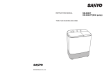
TRANSPORTING YOUR GAME
It is recommended that you move your game with the legs removed. Any time the
game is moved you should remove the back box to avoid damage.
GAME DIMENSIONS AND WEIGHT
Your new pin game weighs 100 pounds while in the box
The game itself weighs 90 pounds complete
18.5"
25
"
24.5"
Page 1
45"
40"
29.75"
19.
48.25"
Box Dimensions
43.75"
PACKING LIST
Your new game comes with many parts. The following is the packing list.
The main box comes with the following in it:
· ScoreGasm pin game
· 4 Wooden legs
· 1 Backbox with DMT sound system
· Goody box
The goody box includes:
· User Manual
· Leg Bolts
· Leg Brackets
· Leg Levelers
· 10 Pinballs
· 3 Fuse bags, 1A, 2A, 4A
· Power Cord
· Red Tilt Ring
· 2 Tilts balls
· SD Card adapter
· Backbox harness
· Backbox dowels
· USB Thumbdrive in large bag
· Keychain
Page 2
GAME CONTROLS
The following 3 pages will help you familiarize yourself with your new game!
Backbox with 2" speakers
and lit marquee
Adjustable Tilt
Ball Plunger
Ball Lifter
Baffle Board Reset Plunger
Page 3
PLAYFIELD LAYOUT
ScoreGasm Hole
Shoot this hole to advance
your progressive scoring
Upper Progressive Scoring Hole
Load a ball into this hole
and then shoot the
ScoreGasm hole to advance
your score
Lower Progressive Scoring Hole
Load a ball into this hole and
then shoot the ScoreGasm
hole to advance your score
Drain Hole
Avoid at all costs
Page 4
THE SERVICE PANEL
The service panel contains the power switch, power plug, main fuse, sound control
buttons, antenna port and the volume control. Here are the details.
Main Power IEC Power
Switch
Plug
Main Fuse
2 Amp
Fast-Blo
Voltage
Selector,
NOT USED
Sound
Controls
Wireless
Remote
Option
Antenna
Port
Music Select - Allows you to pick the song playing. That single song loops.
Mute - No music at all, game sounds still play.
FUN! - Allows you to hear all of the sounds loaded in the game.
All Songs - Plays all songs loaded in the game in a row.
Page 5
Volume
Control
SETTING UP YOUR GAME
Unpacking your game. Please be sure to work safely, it is recommended to have at least
2 people setting up the game.
You will need a box cutter and a 9/16" socket wrench to set the game up. You will also
need the goodie box to setup the game.
Open the box. Lay the box on
the floor on the side that is
labeled "Truck this side only"
Remove the backbox from
the foam blocks.
Remove the foam cushions
and the legs.
Slide the game out of the
box.
Tip the game up onto it's
back. Do not use the
shooter rods to lift the
game!
Install leg levelers. The leg
levelers are found in the
goodie box.
From the goodie box, place
the leg protectors on the
outside of the leg and
install the leg bolts.
Be sure to push the leg up
into the game while
tightening the bolts. This
will help protect the
cabinet art.
Lower the game onto its
front legs.
Page 6
SETTING UP YOUR GAME
From the goodie box, place
Lift the back of the game
and have your helper hold it the leg protectors on the
outside of the leg and
up.
install the leg bolts.
Be sure to push the leg up into
the game while tightening the
bolts. This will help protect the
cabinet art. Do not overtighten
the leg bolts to avoid leg damage.
Open the back door of the
game.
Slide the playfield glass
partially out and install 10
balls.
Install the tilt ring and the
tilt ball. The larger ball is
easier to tilt.
Reset the game using the
baffle plunger.
Reinstall the back door. If
you are installing your
backbox, please go to the
next page. If not, plug the
game in.
Enjoy.
Page 7
INSTALLING THE BACK BOX
Your new game includes a back box. The back box includes some LED lighting for the
marquee as well as speakers for a more immersive experience.
There are two holes located Install the dowels into these
With the game off, locate
the goodie box and find the on the topmost panel at the holes. No glue is needed.
back of the game.
two wooden dowels.
There are two matching
holes located on the bottom
of the backbox. Align these
holes and place the topper
on the dowels.
Locate the backbox harness
from the goodie box.
Open the back door of the
game and feed the harness
through the provided hole in
the cabinet. The side with two
plugs goes into the game.
Push the rubber grommet
flush with the cabinet.
Install the 2 position plug
into the harness provided
near the hole. This is the
connection for the
speakers.
Install the 3 positon plug
into the power port on the
power board.
Connect the harness to the
backbox. Reinstall the back
door. The game is now
ready to play.
Page 8
LEVELING THE GAME
The game is designed so that when all 4 leg levelers are installed all the way up the
game playfield is set at 3.5 degrees. This allows the game to play as designed.
Changing the pitch will cause changes in game play, and can be undesireable.
Use an inclinometer placed directly on the playfield to determine pitch. Keep in mind
that this is not like a modern pinball machine, you want the ball speed to be slower
and more controllable when you nudge. Optimum pitch is between 3 and 4 degrees.
ADJUSTING SOLENOID POWER
Do not attempt to make ANY adjustments to the game unless it is
UNPLUGGED. There is high voltage present in the game and it should be off
and unplugged anytime you service it.
Unplug the game and open
the back door.
Unplug the playfield.
Locate the workboard in the You may need to remove
game.
the plastic saftey guard
from the game.
Page 9
Slide the playfield out of
the cabinet.
ADJUSTING SOLENOID POWER
Do not attempt to make ANY adjustments to the game unless it is
UNPLUGGED. There is high voltage present in the game and it should be off
and unplugged anytime you service it.
Turn this pot to adjust the firing
power of the coils.
Clockwise is more power.
Counter-Clockwise is less power.
LINE VOLTAGE IS ON
THESE THREE SCREW
TERMINALS. IF LEFT
PLUGGED IN TOUCHING THESE SCREW
TERMINALS COULD KILL YOU. DO NOT
TOUCH!
Page 10
SETTING LINE VOLTAGE TO 230 VOLTS
Do not attempt to make ANY adjustments to the game unless it is
UNPLUGGED. There is high voltage present in the game and it should be off
and unplugged anytime you service it.
Unplug the game and open
the back door.
Unplug the playfield.
Slide the playfield out of
the cabinet.
Locate the workboard and
remove the acrylic shield
attached by the power
suppy.
Loosen the one remaining
screw.
Flip the power supply over
and slide the switch to the
230V position.
Reattach the power supply
and the acrylic shield.
Swap out the main fuse
with a 1A amp fast-blo.
Reinstall the playfield and
back door. You may need to
adjust the solenoid power
once this is complete.
Page 11
CUSTOMIZING YOUR MUSIC & SOUNDS
ScoreGasm uses an open source polyphonic sound module called WAV Trigger
provided by Spark Fun and created by Robertsonics. To customize your music, you will
need familiarize yourself with the hook-up guide found at:
http://robertsonics.com/wav-trigger-online-user-guide/
Our game is wired as follows:
Trigger 1: Used as an inverted input to start music on power on. Should not be modified.
Trigger 2: Music Play, plays tracks 1 - 99 sequentially when triggered and loops the track.
Trigger 3: Mute, Stop the music
Trigger 4: Sound Effect, plays a random track 100 - 199
Trigger 5: Music Plays, plays tracks 1 - 99 in order
Keep in mind that all music and sound tracks should be saved as stereo WAV files,
44.1kHz, 16bit sound.
Music files should be named a 3 digit number, from 001 to 099, followed by an
underscore and a unique name. Example: 001_KeepYourEyeOnTheSGM.WAV
Sound files should be named a 3 digit number, from 100 to 199, followed by an
underscore and a unique name. Example: 100_Willhelm.WAV
Page 12
RESETTING YOUR SOFTWARE
Should you like to restore your software to the factory state you can find a restore
utility on the thumb drive provided in the goodie box. You can also download a copy
from our website at www.dayonepinball.com
To reset the software:
1) Turn off and unplug the game.
2) Remove the SD card from the WAV trigger board.
3) Insert the SD card into your Windows based PC.
4) Run the restore executable.
5) Follow the on screen prompts.
6) Software will delete the entire contents of the specified drive.
Choose wisely!
Once done, reinstall the SD card into the WAV trigger board.
Page 13
THIS PAGE INTENTIONALLY UNINFORMATIVE
MECHANICAL
DRAWINGS
Page 15
PLAYFIELD SANDWICH
Page 16
KICKOUT MECHANISM
Page 17
THIS PAGE INTENTIONALLY UNINFORMATIVE
SCHEMATICS
Page 19
SOUND BOARD
10-0001-000-01
For full details
on the sound
board, please
follow this link.
or visit:
http://robertsonics.
com/
Page 20
POWER BOARD
10-0002-000-01
Identifier
Part Type
Part Value
X1
Connector
10 Position .156 Header with locking ramp
Connector
4 Position .156 Header with locking ramp
Fuse
4A AGC Slow-Blo Fuse
U2
Fuse
1A AGC Fast-Blo Fuse
X1
Connector
10 Position .156 Header with locking ramp
Connector
4 Position .156 Header with locking ramp
Resistor
150Ω SMD
R2
Resistor
510Ω SMD
LED1
LED
Green T1 Through Hole LED
LED2
LED
Green T1 Through Hole LED
X2
U1
X2
R1
Page 21
DRIVER BOARD
10-0003-000-01
Identifier
Part Type
Part Value
P1
Connector
5 Position .156 Header with locking ramp
Connector
4 Position .156 Header with locking ramp
Resistor
1kΩ 1/4 watt
R2
Resistor
680Ω 1/2 watt
D1
LED
Green T1 Through Hole LED
Q1
TRANSISTOR
2N4401 NPN Transistor
Q2
TRANSISTOR
TIP102 NPN Darlington Transistor
X2
R1,R3
Page 22
WORKBOARD LAYOUT
Sound Board
Power Supply
Page 23
Power Board
Amplifier
Sounds Controls
Power Entry Module
DAY
ONE
PINBALL
MANUFACTURING,
INCORPORATED
LIMITED
WARRANTY
DAY ONE PINBALL MANUFACTURING, INC., (" SELLER" ) WARRANTS ONLY THE INITIAL PURCHASE OF ITS
PRODUCTS THAT THE ITEMS LISTED BELOW ARE FREE FROM DEFECTS IN MATERIAL AND WORKMANSHIP
UNDER NORMAL USE AND SERVICE FOR THE WARRANTY PERIOD SPECIFIED:
PRINTED CIRCUIT BOARDS: 9 MONTHS
NO OTHER PARTS OF SELLER'S PRODUCT ARE WARRANTED.
WARRANTY PERIODS ARE EFFECTIVE FROM THE INITIAL DATE OF SHIPMENT FROM SELLER TO ITS AUTHORIZED
DISTRIBUTOR, OR WHEN PURCHASED DIRECTLY FROM THE SELLER, FROM THE DATE SHIPPED FROM SELLER TO
ITS CUSTOMER.
SELLER'S SOLE LIABILITY SHALL BE, AT ITS OPTION, TO REPLACE OR REPAIR PRODUCTS WHICH ARE RETURNED
TO SELLER DURING THE WARRANTY PERIODS SPECIFIED, PROVIDED:
1 . SELLER IS NOTIFIED PROMPTLY UPON DISCOVERY BY PURCHASER THAT STATED PRODUCTS ARE DEFECTIVE.
2. SUCH PRODUCTS ARE PROPERLY PACKAGED AND RETURNED FREIGHT PREPAID TO THE SELLER.
THIS WARRANTY DOES NOT APPLY TO ANY PARTS DAMAGED DURING SHIPPING AND/OR DUE TO IMPROPER
HANDELING, OR DUE TO IMPROPER INSTALLATION OR USAGE, OR ALTERATION. IN NO EVENT SHALL THE
SELLER BE LIABLE FOR ANY ANTICIPATED PROFITS, LOSS OF PROFITS, LOSS OF USE, ACCIDENTAL OR
CONSEQUENTIAL DAMAGES OR ANY OTHER LOSES INCURRED BY THE CUSTOMER IN CONNECTION WITH THE
PURCHASE OF THE SELLERS PRODUCT.
WARRANTY DISCLAIMER
EXCEPT AS SPECIFICALLY PROVIDED IN A WRITTEN CONTRACT BETWEEN SELLER AND PURCHASER, THERE ARE
NO OTHER WARRANTIES, EXPRESS OR IMPLIED, INCLUDING ANY IMPLIED WARRANTIES OF MERCHANTABILITY
OR FITNESS FOR A PARTICULAR USE.
CAUTIONS, WARNINGS AND NOTICES
Caution
Always disconnect the line voltage before servicing. Some parts will still hold current when
uplugged.
FOR SAFETY AND RELIABILITY, SUBSTITUE PARTS AND EQUIPMENT MODIFICATIONS
ARE NOT RECOMMENDED (AND MAY VOID ANY WARRANTIES.) USE OF NON-DAY ONE PINBALL MFG,
INC. PARTS OR MODIFICATIONS OF GAME CIRCUITRY, MAY ADVERSELY AFFECT GAME PLAY, OR MAY CAUSE
INJURIES. TRANSPORT PIN GAMES WITH BACK BOX REMOVED! ALWAYS TAKE CARE WHEN SERVICING ANY
GAME. ALWAYS READ THE SERVICE MANUAL BEFORE REPLACING OR SERVICING COMPONENTS.
Warning
THIS EQUIPMENT GENERATES, USES AND CAN RADIATE RADIO FREQUENCY ENERGY, AND IF NOT
INSTALLED AND USED IN ACCORDANCE WITH THE INSTRUCTIONS MANUAL, MAY CAUSE INTERFERENCE
TO RADIO COMMUNICATIONS. OPERATION OF THIS EQUIPMENT IN A RESIDENTIAL AREA IS LIKELY TO CAUSE
INTERFERENCE IN WHICH CASE THE USER AT THEIR OWN EXPENSE WILL BE REQUIRED TO TAKE WHATEVER
MEASURES MAY BE REQUIRED TO CORRECT THE INTERFERENCE.
Notices
THIS DOCUMENT AND THE DATA DISCLOSED HEREIN OR HEREWITH IS NOT TO BE REPRODUCED, USED OR
OTHERWISE DISCLOSED IN WHOLE OR IN PART TO ANYONE WITHOUT WRITTEN CONSENT FROM DAY ONE
PINBALL MANUFACTURING, INC. PRODUCTS IN THIS MANUAL, THE COMPANY NAME, DEVICES AND THE
DESIGN OF THE MANUAL ITSELF ARE PROTECTED BY COPYRIGHTS, TRADEMARKS AND DESIGN
REGISTRATIONS. ACTION WILL BE TAKEN IN THE EVENT OF INFRINGEMENT OR IMITATION.