1
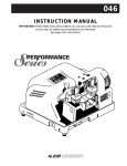
030 and 031
INSTRUCTION MANUAL
IMPORTANT! Read these instructions before you use your new 030 or 031 Key Machine.
Model No. 030
for duplicating
Safe Deposit Keys
Model No. 031
for duplicating
The Half-Time
Key Machines
Detention Keys
USA: 400 Jeffreys Rd., P. O. Box 2627, Rocky Mount, NC 27802-2627 • Tel: (919) 446-3321 • FAX: (919) 446-4702
EXPORT: 7301 Decarie Blvd., Montreal, Que. H49 2G7 • Tel: (514) 735-5411 • FAX: (514) 273-3521
This manual is registered and applies specifically to the
machine which carries this serial number. It properly identifies your model and assures you will receive correct parts,
if and when you require replacement parts. Retain this manual in a safe place. It’s the only one of its kind. If ownership of this machine is transferred, this service manual
should accompany the machine.
When seeking service information about this machine,
refer to the Model No. (which is 030 or 031), your registration number (see below) and the part number desired (see
pages 6 to 8). Note that many parts used on these two key
machines are interchangeable.
CONTENTS
Warranty ........................................................................................................................2
Introduction to the 030 and 031 ....................................................................................3
Operating Parts (Illustrated) ..........................................................................................4
Operating Parts Identification (Names and Part Numbers) ..........................................5
Exploded View ..............................................................................................................6-7
Exploded View Parts List ..............................................................................................8
Optional Kits ..................................................................................................................8
The Cutting Operation ..................................................................................................9
How to Duplicate Keys ..................................................................................................10-11
Replacements and Adjustments ....................................................................................12
ONE YEAR LIMITED WARRANTY
ILCO UNICAN warrants to the original buyer of any new
model 030 or 031 machine that it will repair or replace, at its
option, any part of any machine which proves, to the reasonable satisfaction of ILCO UNICAN, to have defects arising
from the faulty manufacture of the machine or from defective
material or components, during a period of one (1) year from
the date of shipment of the machine by ILCO UNICAN, provided that the machine is returned by prepaid transport to ILCO
UNICAN or to its authorized representative before the expiry
of the warranty period together with a detailed description of
the alleged defect(s). ILCO UNICAN may, at its discretion,
elect to refund the purchase price allowable to the part affected, or to issue a credit if the price therefore remains unpaid.
ILCO UNICAN sells precision-made machines. The buyer
assumes all risks, and ILCO UNICAN shall not be liable for
any reason, if the machine has been subjected to improper installation, improper use, improper or inadequate maintenance,
negligence, if any unauthorized modification or alteration is
made to the machine, or in case of accident. For greater certainty, any machine not operated in accordance with ILCO
UNICAN’s printed instructions or operated beyond its rated
capacity shall not be covered by this or any other warranty.
Registration and Serial number is
2
Any and all warranties made by ILCO UNICAN on any machine, product, or component thereof shall be effective only if
and for so long as the buyer complies with all payment obligations pursuant to the buyer’s accepted and acknowledged order.
Failure to meet such payment obligations shall void all warranties and not extend the period of time for which such machine,
product of component thereof is warranted irrespective of
whether or not payment is eventually made.
These warranties are in lieu of and not in addition to any
other warranty of condition, expressed or implied, including
without limitation merchantability, fitness for a particular purpose or latent defects. The buyer releases ILCO UNICAN from
any liability for any reason other than a breach of its warranties
hereunder.
The liability of ILCO UNICAN shall in no case, including
negligence, exceed the purchase price of the defective machine,
nor shall ILCO UNICAN be liable for any personal injuries,
property damage or consequential damages.
Use only genuine ILCO UNICAN replacement parts on this
machine!
INTRODUCTION
Congratulations!
You’ve purchased a superior key cutting machine.
The Half-Time key machine you've just received will give
you remarkably fast and accurate keys for many years to
come… and a profitable return on your investment. It will
save you time and money.
inch cutting wheel, made out of solid carbide. The cutter is
a slotter type and is intended to make plunge cuts only. It is
NOT a side milling slotter. Standard on the Half-Time
Model 030 is a cutter that is .055" thick, capable of making
a plunge cut which is .055" wide. Since there are safe
Specifically engineered to cut safe deposit keys, the Half- deposit locks on the market with wider key cuts, optional
Time is crafted with uncompromising quality for the profes- cutters are available in thicknesses of .062", .072", and
sional who is serious about speed, accuracy and profitabili- .088".
ty. It will let you duplicate keys faster because it's designed
to cut TWO keys at a time; hence, the name Half-Time. There are two Half-Time models available: the 030 which
This capability of cutting two accurate keys at the same time is designed for safe deposit keys, and the 031, which is
is unique in the industry. No other flat key duplicator designed for cutting large detention (jail) keys. In addition,
accomplishes this feat.
the 030 or the 031 can be modified to cut the large paracentric Mogul key. The parts necessary for these modifications
To cut two keys at the same time, the Half-Time uses a 4 are available in optional kits.
UNPACKING INSTRUCTIONS
Your Half-Time key machine has been shipped to you in a
sturdy, specially cushioned container to prevent the possibility of damage during handling and shipment. Once the
machine is removed from the carton, it should be set up on
a level workbench and wiped free of all rustproofing oil.
The machine is adjusted at the factory and test keys have
been cut on it, but it is recommended that you check the adjustments to make sure they have not slipped or shifted during transit (See Page 12 “ADJUSTMENT FOR CUT
SAFETY
The Half-Time has been engineered to originate and to duplicate flat keys. It is not intended or designed for any other
purpose. The machine operator assumes all liability when
using this machine in a manner inconsistent with its stated
design purpose.
ILCO UNICAN strongly recommends the use of protective
eye glasses or goggles when operating this machine, or
when in the vicinity of the machine while it is being operated. Protective eye wear prevents injuries!
Note that this machine does not turn off automatically when
the carriage is lowered.
When the key machine is operating, be careful not to butt
the vise jaw or carriage against the cutting wheel as this will
cause damage to the cutter, jaw, or carriage.
DEPTH”).
DO NOT DESTROY OR DISCARD THIS VALUABLE SHIPPING CARTON.
CAUTION! STORE IT CAREFULLY IN A SAFE PLACE. IN THE EVENT OF A PROBLEM
WITH YOUR MACHINE, IT MUST BE RETURNED TO OUR SERVICE FACILITY
IN ITS ORIGINAL PROTECTIVE CARTON.
3
OPERATING PARTS
Vise
Handle
Assembly
Key
Stop
Key
Guide
Stop
Nut
Cutter Cutter
Guard
Cap
Screw
Vise
Handle
Assembly
Key
Guide
Spindle
Retainer
Key
Guide
On/Off
Indicator
Light
Key
Guide
Housing
On/Off
Switch
Motor
Bottom Vise
Jaw (left)
Carriage
Guide Bar #2
Guide Bar # 1
(two)
Guide Bar #3
Mounting
Plate
Top
Vise
Jaw
Carriage
Knob
Bottom
Vise Jaw
(right)
4
Base
OPERATING PARTS IDENTIFICATION
Refer to page 4
Part No.
030-1
030-3
030-6
030-7
030-8
030-10
030-14R
030-14L
030-15
030-19
030-20
030-21
030-22
030-23
030-24
030-27
030-28
030-41
030-42
CU30-55
Identification
Base
On/Off switch
Carriage guide bar #1 (two)
Carriage guide bar #2
Carriage guide bar #3
Carriage
Bottom vise jaw (right)
Bottom vise jaw (left)
Top vise jaw (two)
Vise handle assembly (two)
Key stop (two)
Key guide housing
Key guide spindle
Key guide
Key guide stop nut
Key guide spindle retainer
Cutter guard and support
Carriage knob (two)
On/Off indicator light
Carbide cutter, .055" thick
5
EXPLODED VIEW
6
EXPLODED VIEW
7
EXPLODED VIEW PARTS LIST
Refer to pages 6 and 7 for illustrations.
Part No.
Description
Part No.
030-1
030-2
030-3
030-4
030-5
Base
Motor Bracket
On/Off Switch
Foot pad (four)
Mounting plate
030-25
030-26
030-27
030-28
030-29
Key guide spindle spring
Key guide spindle cap
Key guide spindle retainer
Cutter guard and support
Cutter spindle
030-6
030-7
030-8
030-9
030-10
Carriage guide bar #1 (two)
Carriage guide bar #2
Carriage guide bar #3
Lower support (two)
Carriage
030-30
030-31
030-32
030-33
030-34
Spindle washer
Belt guard
Grommet (three)
Power cord and plug
V belt
030-11
030-12
030-13
030-14R
030-14L
Vise table
Dowel sleeve, 1/4" (twelve)
Dowel sleeve, #10 (four)
Bottom vise jaw (right)
Bottom vise jaw (left)
030-35
030-36
030-37
030-38
030-39
Key guide dowel pin
Hood label for 030
Spacer Bearing
Key guide spindle travel pin
Flat head screw (two)
030-15
030-16
030-17
030-18
030-19
Top vise jaw (two)
Shim
Vise jaw springs (four)
Socket head cap screw
Vise handle assembly (two)
030-40
030-41
030-42
030-43
030-44
Socket head set screw (two)
Carriage knob (two)
On/Off indicator light
Plunger (two)
Flat head screw
030-20
030-21
030-22
030-23
030-24
Key Stop (two)
Key guide housing
Key guide spindle
Key guide
Key guide adjusting collar
030-45
030-46
030-47
030-48
030-49
Motor pulley
Flat head screws (twelve)
Socket head set screw (two)
Round head screws (three)
Socket head set screws (four)
Description
Part No.
Description
030-50
030-51
030-52
030-53
030-54
to 58
030-59
Dowel Pin (two)
Socket head set screws (four)
Vise jaw washer (three)
Socket head cap screws (two)
Cutters, see below
030-60
030-61
030-62
030-63
030-64
030-80
030-82
Hex head screw (three)
Flat washer
Hex nut, #8 (four)
Lock washers, #8 (four)
Socket head set screws (five)
Motor
Spacer washer
CU30-M
Cylinder cutter for Mogul
keys
Carbide cutter, .055" thick
Carbide cutter, .062" thick
Carbide cutter, .072" thick
Carbide cutter, .088" thick
CU30-55
CU30-62
CU30-72
CU30-88
Cutter pulley
OPTIONAL KITS
030-CK
This kit is intended for the person who has an 031 (detention) key machine and the person wants to convert it to cut
safe deposit keys. The 030-CK kit includes:
1 only CU30-55 cutter
2 only key stops, Part No. 030-20
2 only screws, Part No. 030-53
031-CKM
This kit is intended for the person who has an 030 (safe deposit) or and 031 (detention) key machine. The person
wants to cut the large paracentric cylinder key (Mogul). The 031-CKM kit includes:
1 only CU30-M cutter
1 only key guide (131480)
2 only key stops (131477)
2 screws (174080)
031-CK
This kit is intended for the person who has an 030 (safe deposit) key machine and the person wants to cut the detention key (lever key with plunge cuts). The 031-CK kit includes:
1 only CU30-88 cutter
2 only key stops (131477)
2 only screws (174080)
8
THE CUTTING OPERATION
SETTING UP YOUR KEY MACHINE
The 030 and 031 key machines are shipped completely
assembled. Each one is ready for use upon unpacking.
When placing either machine on a table or work bench, it is
essential that the surface be level; if not level, the X - Y
action of the carriage may bind during operation. Also, the
machine can be bolted to the work bench for stability. If you
decide to bolt it down, make sure the surface is level and all
four bolts or screws are tightened equally. A torque wrench
is ideal, but not necessary.
is set on a level surface, the sliding action is smooth and
easy; a non-level surface may cause binding in the slide
action.
The X - Y action is the term given to the engineer's description of the carriage movement, X referring to the horizontal
axis and Y to the vertical axis. This means that the carriage
can move horizontally (left to right) as well as vertically (up
and down). In order to accomplish this action, the carriage,
and the guide bars along which the carriage slides, are
machined to extremely close tolerances. When the machine
If you decide not to bolt down the machine, we have provided rubber feet which can be applied to the bottom of the
machine base. This will ensure a non-skid, non-scratch surface for the machine. To install the rubber feet, peel the
backing from each foot and apply the adhesive side to the
bottom of each corner of the machine base. Additional
adhesive is not needed.
In the event the machine is bolted down, and binding occurs
in the slide action, loose the bolt at one corner and check the
slide action until it is smooth. Then, loosen and retighten
the other bolts to a point where the machine is secure while
the X - Y action remains smooth.
GENERAL OPERATING SEQUENCE
Two hands must be used to cut a key on the 030 and 031.
The left hand grasps the left carriage knob and the right
hand grasps the right knob. Both hands then are moved
sideways or up and down to make the cuts in the key blank
(See Figure 1).
Figure 1
mits the operator to pre-position the key guide into a specific cut of the pattern key before the blank touches the cutter.
This is very helpful when making adjacent cuts where the
depths are only one or two apart.
Aligning the key blank to the pattern key is done by placing
the shoulders of both keys (not the tips) against the key
stops. In this position, the sideways travel of the carriage is
far enough to enable cutting of a throat cut, if one is present
in the key.
The 030 machine is capable of cutting TWO key blanks at
the same time. This capability is possible because of the X
- Y action of the carriage and the large diameter of the cutting wheel. The wheel is 4" in diameter and its' arc at the
point of cutting is flat enough to make cuts that are perpendicular and accurate in both keys. Being able to cut two
keys at the same time will reduce your cutting time in half.
In addition, the cutter is made of solid carbide and will last
much longer than cutters made of conventional steel.
The key guide is spring loaded and this provides a pre-positioning action. In its normal position, the key guide protrudes further forward than the cutter. This extra length per-
9
HOW TO DUPLICATE KEYS
SAFE DEPOSIT KEYS
The key cutting procedure for safe deposit keys is as follows:
1. Clamp the pattern key (original) in the right vise jaw. Push
this key into the vise jaw until its shoulder contacts the key
stop (See Figure 2).
2. Tighten the right vise jaw. Note that the vise jaw is
5.
6.
Figure 2
7.
8.
9.
motor is running. The light is needed since the machine
operates quietly and is vibration free.
Grasp the carriage as shown in Figure 1 and move the carriage up to the key guide. Move the carriage to line up the
key guide with the first cut in the pattern key.
Push the carriage upward so the key guide drops into the
first cut. When it does, continue pushing upward; the cutter will make the first cut.
When the cutter completes the cut, lower the carriage and
shift it to the next cut. Repeat the previous steps for all
remaining cuts in the pattern key.
Move the on/off switch to turn off the machine. The indicator light should go off.
Remove the key(s) and brush off any burrs by running the
key under a brush or a small file.
ABOUT CUTTING KEYS
Key
Stop
designed so only light pressure is needed to clamp the key
securely. Do not overtighten. Only a 1/4 turn of the handle is all that should be needed to release the vise jaw.
NOTE! If excessive pressure is used to tighten the vise
jaw, the threads in the bottom vise jaw will be strained and
will eventually strip out, requiring replacement of the bottom jaw. The handle itself is placed on a ratchet type bolt
and can be repositioned easily by lifting and turning to the
most comfortable position.
3. Select the proper key blank for duplication. Then, insert
one or two of these blanks into the left vise, butting the
shoulder(s) against the key stop (See Figure 3). Tighten
the left vise jaw.
4. Activate the on/off toggle switch to turn on the machine.
Figure 3
It makes no difference whether one or two key blanks are
clamped in the left vise jaw; the machine will duplicate one
or two with equal accuracy. When two keys are cut, only the
bottom key will have burrs and require deburring (brushing).
The top key has no burrs.
ABOUT THE CUTTER - KEY GUIDE
The cutter used on the 030-031 is 4" in diameter and is made
out of solid carbide. It is a slotter type cutter, having no
millings or cutting edges on the sides. Therefore, the cutter
makes plunge cuts only, that is, it will cut straight into the
key blank and cannot be moved side to side to widen the
cuts. Do not attempt sideward movement to force the key
against the sides of the cutter, as if to widen the cuts or to
skip to the adjacent cut. The sideward pressure will put
undue strain on the cutter and could cause a tooth to chip or
break off. When the key guide is bottomed into a cut, push
the carriage up only and then back down when the cut is
complete.
Since there are safe deposit locks with varying cut widths,
four cutters are available in thicknesses of .055", .062",
.072", and .088". The cutter provided with the 030 machine
is .055" thick, identified as CU30-55. The cutter on the 031
machine is .088" thick, identified as CU30-88.
Because each cutter requires a matching key guide to the
same thickness, the 030 and 031 are provided with a key
guide that has all four thicknesses on it. The guide just has
to be rotated to the thickness desired. To rotate the key
guide, loosen its retaining screw and pull it off its positioning lug. (See Figure 4).
The yellow light near the switch will go on, indicating the
10
HOW TO DUPLICATE KEYS
Figure 4
right side of each vise. Note the new key stops (131477) are
thick and require longer screws.
Figure 5 shows the large paracentric key (Mogul) installed
in the vise jaws, ready for cutting. For cutting the duplicate
key, the carriage is shifted sideways to the left, with the key
blank passing across the cutter, just as with conventional
duplicating.
CUTTING DETENTION KEYS
The large lever type keys used in detention locks are cut on
the 031 machine. The cuts are made in the bit portion of the
blank and could be from .088" to .104" wide. As a result, the
cutter provided on the 031 is .088" thick, identified as CU3088. It requires the .088" key guide.
CUTTING MOGUL TYPE KEYS
Large paracentric cylinder keys, such as the Mogul or
Adams, can be cut on the 030 and 031 machines if the cutter
and key guide are changed. The cutter and key guide are
packaged in a separate kit, identified as 031-CKM. Also
included are two key stops and screws. Identification of the
parts is as follows: Cutter (CU30-M), Key Guide (131480).
Key Stops (131477), Screws (174080).
Figure 6 shows the detention keys installed in the vise jaws,
ready for duplicating. Note the keys gauge from the bottom
shoulder, using the same key stops required for Mogul keys.
Once the pattern key and the key blank are clamped in the
vise jaws, the actual cutting procedure is the same as that for
the safe deposit keys.
The only differences between the 030 machine and the 031
To install these parts on either machine, first remove the key machine are the cutters and key stops. A person who already
guide. Then, set the Mogul key guide (Part No. 131480) on has an 030 machine (for cutting safe deposit keys) can conthe key guide spindle, with the V-shape tip pointing toward vert to an 031 by installing the kit 031-CK. Identification of
the vise jaw. Next, using a suitable wrench, remove the cut- parts in 031-CK is as follows: Cutter (CU30-88), Key Stops
ter nut, washer and cutter. Install the CU30-M cutter, replac- (131477), Screws (174080).
ing the spacer washer and cutter nut. Note the CU30-M is a
milling cutter and should be installed with the teeth rotating Likewise, a person who already has an 031 machine can
convert to an 030 machine (for cutting safe deposit keys) by
down.
installing the kit 030-CK. Identification of the parts in 030Since these large paracentric keys gauge like conventional CK is as follows: Cutter (CU30-55), Key Stops (030-20),
size cylinder keys, different key stops are required on the Screws (030-53).
Figure 5
Figure 6
11
REPLACEMENTS AND ADJUSTMENTS
When the cutter becomes dull, it should be replaced. There
are three ways to determine if the cutter is dull:
Figure 8
1. By sound - a dull cutter will emit a high shrilly sound.
2. By time - a dull cutter will take longer to make the cuts.
3. By the burrs - if the burrs on the back side of the key blank
are formed into little mounds, the cutter is not chipping
away the metal but actually rolling it over. If there is a lot
of burrs , the cutter is dull.
To remove the cutter, use two open end wrenches, as shown
in Figure 7. Note that the cutter nut is reverse threaded. After
the new cutter is installed, the adjustment of the machine
should be checked and corrected, if needed.
Figure 7
1. For cuts that are too deep, rotate the adjusting collar clockwise.
2. For cuts that are too shallow, rotate the adjusting collar
counterclockwise.
ADJUSTMENTS FOR CUT DEPTH
As with all key duplicating machines, the key guide must be
set in the same plane as the cutter in order to reproduce the
correct depths of the pattern key. The depth of cut is regulated by the key guide adjusting collar which is threaded on
the key guide spindle. Two set screws secure the collar to the
spindle. Also, the collar is notched in increments of .001" so
rotations of the collar can be measured.
To perform the adjustments, insert the same type key blank
into each vise jaw. Slide the carriage up until the right blank
touches the key guide. Note the cutter, it should be touching
the left key blank. Slowly rotate the cutter by hand; the cutter should be barely touching the key blank.
If the cutter will not rotate, the key guide will make cuts that
are too deep. If the cutter rotates but does not contact the key
blank, the key guide will make cuts that are too shallow. For
either adjustment, locate and loosen the two small set screws
securing the adjusting collar to the key guide spindle. Note
the index mark on the key guide housing; then, rotate the collar as follows (See Figure 8):
12
By rotating the collar one increment mark at a time, you'll be
able to make fine adjustments. A test key, cut to each of the
depths in a given lock and then measured by micrometer,
should be used to verify the accuracy of the key guide adjustment. Be sure the collar screws are tightened securely when
the adjustment is correct.
MAINTENANCE
• Keep the machine free of excessive dirt, dust and chips.
• It's a good idea to occasionally lubricate the bearing surfaces with a very light amount of oil and then wipe off the
oil with a clean dry cloth.
• Inspect all screws and keep them snug.
• Note that the motor is a sealed bearing type and requires no
lubrication.
• If the carriage movements are sluggish and bind, check the
guide bars for dirt and chips; wipe these clean. Also check
to see that the machine is level. If it's not level, correct the
machine mounting as explained in the section "Setting Up
Your Key Machine" on page 9.
• If the vise jaws do not open or close smoothly, check under
the top jaw for cleanliness. Apply a very light coat of oil
and wipe it off with a clean dry cloth.