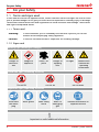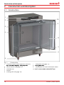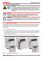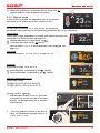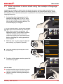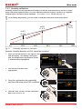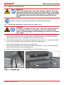
1
ICH ICH L OPERATING INSTRUCTIONS CLIMATE CHAMBER ICH/ICH L 100% ATMOSAFE. MADE IN GERMANY. www.memmert.com | www.atmosafe.net Manufacturer and customer service Memmert GmbH + Co. KG Willi Memmert Straße 90-96 D-91186 Büchenbach Deutschland Phone: +49 (0)9122 925-0 Fax: +49 (0)9122 14585 E-mail: [email protected] Internet: www.memmert.com Customer service: Service hotline: +49 (0)9171 9792 911 Service fax: +49 (0)9171 9792 979 E-mail: [email protected] When contacting customer service, always quote the product serial number on the nameplate (see page 13). Shipping address for repairs: Memmert GmbH + Co. KG Kundenservice Willi-Memmert-Str. 90-96 DE-91186 Büchenbach Germany Please contact our customer service before sending appliances for repair or before returning equipment, otherwise, we have to refuse acceptance of the shipment. © 2014 MEMMERT GmbH + Co. KG Date 10/2014 We reserve the right to make changes About this manual About this manual Purpose and target audience This manual describes the setup, function, transport, operation and maintenance of climate chambers ICH and ICH L. It is intended for use by trained personnel of the owner, who have the task of operating and/or maintaining the respective appliance. If you are asked to work on the appliance, read this manual carefully before starting. Familiarise yourself with the safety regulations. Only perform work that is described in this manual. If there is something you do not understand, or certain information is missing, ask your manager or contact the manufacturer. Do not do anything without authorisation. Versions The appliances are available in different configurations and sizes. If specific equipment features or functions are available only for certain configurations, this is indicated at the relevant points in this manual. The functions described in this manual refer to the latest firmware version. Due to individual configurations and sizes, illustrations in this manual may be slightly different from the actual appearance. Function and operation are identical. Other documents that have to be observed: ► For operation of the appliance with MEMMERT AtmoCONTROL, observe the separate software manual ► For service and repair work (see page 57), observe the separate service manual Storage and resale This instruction manual belongs with the appliance and should always be stored where persons working on the appliance have access to it. It is the responsibility of the owner to ensure that persons who are working or will work on the appliance are informed as to the whereabouts of this instruction manual. We recommend that it is always stored in a protected location close to the appliance. Make sure that the instruction manual is not damaged by heat or humidity. If the appliance is resold or transported and then set up again at a different location, the operating instructions must go with it. For the current version of this operating manual in pdf format, please go to www.memmert.com/de/service/downloads/bedienungsanleitung/. www.memmert.com/de/service/downloads/bedienungsanleitung/ D30381 | Date 10/2014 3 Contents Contents 1. For your Safety 1.1 1.2 1.3 1.4 1.5 1.6 1.7 1.8 1.9 Terms and signs used........................................................................................................... 6 Product safety and dangers ................................................................................................ 7 Safety labels ......................................................................................................................... 7 Requirements of the operating personnel .......................................................................... 8 Responsibility of the owner................................................................................................. 8 Intended use ........................................................................................................................ 8 Changes and conversions.................................................................................................... 8 Behaviour in case of malfunctions and irregularities .......................................................... 9 Switching off the appliance in an emergency .................................................................... 9 6 2. Construction and description 2.1 2.2 2.3 2.4 2.5 2.6 2.7 2.8 2.9 2.10 2.11 2.12 Construction ...................................................................................................................... 10 Construction and function ................................................................................................ 11 Material.............................................................................................................................. 11 Electrical equipment .......................................................................................................... 11 Connections and interfaces ............................................................................................... 11 Designation (nameplate) ................................................................................................... 13 Technical data .................................................................................................................... 14 Applied directives and standards ...................................................................................... 15 Declaration of conformity ................................................................................................. 15 Ambient conditions ........................................................................................................... 16 Scope of delivery ............................................................................................................... 16 Optional accessories .......................................................................................................... 16 10 3. Delivery, transport and setting up 3.1 3.2 3.3 3.4 3.5 3.6 For your Safety................................................................................................................... 17 Delivery .............................................................................................................................. 18 Transport............................................................................................................................ 18 Unpacking ......................................................................................................................... 18 Storage after delivery ........................................................................................................ 18 Setting up .......................................................................................................................... 19 17 4. Putting into operation 4.1 4.2 4.3 Connecting the appliance ................................................................................................. 21 Fill up and connect the water tank ................................................................................... 21 Switching on...................................................................................................................... 22 21 5. Operation and control 5.1 5.2 5.3 5.4 5.5 5.6 5.7 Operating personnel.......................................................................................................... 23 Opening the door .............................................................................................................. 23 Loading the appliance ....................................................................................................... 24 Operating the appliance.................................................................................................... 24 Monitoring function .......................................................................................................... 31 Graph ................................................................................................................................. 36 Ending operation............................................................................................................... 37 4 23 D30381 | Date 10/2014 Contents 6. Malfunctions, warning and error messages 6.1 6.2 6.3 Warning messages of the monitoring function................................................................ 38 Malfunctions, operating problems and appliance errors ................................................ 40 Power failure...................................................................................................................... 41 38 7. Menu mode 7.1 7.2 7.3 7.4 7.5 7.6 7.7 7.8 7.9 Overview ............................................................................................................................ 42 Basic operation in menu mode using the example of language selection....................... 43 Setup.................................................................................................................................. 44 Date and Time ................................................................................................................... 47 Calibration ......................................................................................................................... 49 Program ............................................................................................................................. 53 Sound ................................................................................................................................ 54 Protocol ............................................................................................................................. 55 User-ID ............................................................................................................................... 56 42 8. Maintenance and Servicing 8.1 8.2 Cleaning............................................................................................................................. 57 Repairs and Service ............................................................................................................ 59 57 9. Storage and disposal 9.1 9.2 Storage .............................................................................................................................. 61 Disposal ............................................................................................................................. 61 Index D30381 | Date 10/2014 61 62 5 For your Safety 1. For your Safety 1.1 Terms and signs used In this manual and on the appliance itself, certain common terms and signs are used to warn you of possible dangers or to give you hints that are important in avoiding injury or damage. Observe and follow these hints and regulations to avoid accidents and damage. These terms and signs are explained below. 1.1.1 Terms used "Warning" is used whenever you or somebody else could be injured if you do not observe the accompanying safety regulation. "Caution" is used for information that is important for avoiding damage. 1.1.2 Signs used Warning signs (warning of a danger) Danger of electrocution Danger of explosion Gases / vapours Danger of toppling over UV light Hazard area! Observe the operating instructions Prohibition signs (forbidding an action) Do not lift Do not tilt Do not enter Regulation signs (stipulating an action) Disconnect the mains plug Wear gloves Wear safety boots Wear UV safety goggles Observe information in separate manual Other icons Important or useful additional information 6 D30381 | Date 10/2014 For your Safety 1.2 Product safety and dangers The appliances described in this manual are technically sophisticated, manufactured using high-quality materials and subject to many hours of testing in the factory. They contain the latest technology and comply with recognised technical safety regulations. However, there are still risks involved, even when the appliances are used as intended. These are described below. Warning! After removing covers, live parts may be exposed. You may receive an electric shock if you touch these parts. Disconnect the mains plug before removing any covers. Only electrical technicians may work on the electrical equipment of the appliances. Warning! When loading the appliance with an unsuitable load, poisonous or explosive vapours or gases may be produced. This could cause the appliance to explode, and people could be severely injured or poisoned. The appliance may only be loaded with materials/test objects which do not form any toxic or explosive vapours when heated up (see also chapter Intended use on page 8). Warning! In case of appliances of a certain size, you can get accidentally locked in, which is life-threatening. Do not climb into the appliance! 1.2.1 Additional safety regulation for the model ICH L Warning! UV light is a danger to your eyes. Your eyes could be injured by UV light if you do not wear protection. Always wear UV safety goggles when opening the door of the ICH L. This is indicated by the warning signs on the door (see Fig. 1). 1.3 Safety labels The model ICH L has warning labels attached to its door, warning against dangerous UV radiation in the interior (Fig. 1). They indicate that either the lighting has to be switched off or UVsafety goggles are required when the door is opened. These stickers must not be removed and must always be well visible. If they become unrecognisable or if they peel off, they must be replaced. They can be ordered from Memmert customer service. D30381 | Date 10/2014 Fig. 1 Warning sign on the door 7 For your Safety 1.4 Requirements of the operating personnel The appliance may only be operated and maintained by persons who are of legal age and have been instructed accordingly. Personnel who are to be trained, instructed or who are undergoing general training may only work with the appliance under the continuous supervision of an experienced person. Repairs may only be performed by qualified electricians. The regulations in the separate service manual must be observed. 1.5 Responsibility of the owner The owner of the appliance ► is responsible for the flawless condition of the appliance and for it being operated in accordance with its intended use (see chapter 1.6); ► is responsible for ensuring that persons who are to operate or service the appliance are qualified to do this, have been instructed accordingly and are familiar with the operating instructions at hand; ► must know about the applicable guidelines, requirements and operational safety regulations, and train staff accordingly; ► is responsible for ensuring that unauthorised persons have no access to the appliance; ► is responsible for ensuring that the maintenance plan is adhered to and that maintenance work is carried out properly (see page 57); ► has to ensure that the appliance and its surroundings are kept clean and tidy, for example through corresponding instructions and inspections; ► is responsible for ensuring that personal protective clothing is worn by operating personnel, e.g. work clothes, safety shoes and UV safety goggles. 1.6 Intended use Climate chambers ICH and ICH L are suitable for stability testing of pharmaceuticals, cosmetics, food etc under long-term stable ambient conditions. Any other use could be dangerous. In case of any doubts, please contact the Memmert customer service. The appliance is not explosion-proof (does not comply with the German workplace health & safety regulation VBG 24). The appliance may only be loaded with materials and substances which cannot form any toxic or explosive vapours at the set temperature and which cannot explode, burst or ignite. The appliance may not be used for drying, vaporising and branding paints or similar materials the solvents of which could form an explosive mixture when combined with air. If there is any doubt as to the composition of materials, they must not be loaded into the appliance. Potentially explosive gas-air mixtures must not form, neither in the working chamber nor in the direct vicinity of the appliance. 1.7 Changes and conversions No unauthorised changes or alterations may be made to the appliance. No parts may be added or inserted which have not been approved by the manufacturer. Unauthorised changes or alterations result in the CE declaration of conformity losing its validity, and the appliance may no longer be operated. The manufacturer is not liable for any damage, danger or injuries that result from unauthorised changes or alterations, or from non-observance of the regulations in this manual. 8 D30381 | Date 10/2014 For your Safety 1.8 Behaviour in case of malfunctions and irregularities Hauptschalter The appliance may only be used in a flawless condition. If you as the operator notice irregularities, malfunctions or damage, immediately take the appliance out of service and inform your superior. You can find information on eliminating malfunctions from page 38. TEMP FLAP 344.4 °C 40 % Set 444.4 °C 1.9 Switching off the appliance in an emergency Press the main switch at the ControlCOCKPIT (Fig. 2) and disconnect the power plug. This disconnects the appliance from the power supply at all poles. FAN TIMER 02 10 d h End 29 Sept. 22 24 0% UF 110 PLUS ON O N > Zu der Typenbezeichnung gibt es momentan drei Entwu ich kann Ihnen noch nicht sagen, ob Memmert hierzu sc getroffen hat. Die hier gezeigt Variante, ist die von uns empfohlene Ric Fig. 2 Switch off the appliance by pressing the main switch D30381 | Date 10/2014 9 Construction and description 2. Construction and description 2.1 Construction 1 10 2 9 3 4 8 7 6 5 Fig. 3 Construction 1 ControlCOCKPIT with capacitive function keys and LCD displays (see page 25) 2 On/Off switch (see page 22) 3 Door handle 4 Chamber fan 5 Castors 6 Cooling unit (see page 58) 10 7 8 9 Nameplate (see page 13) Inner glass door Illumination box with fluorescent tubes (only for model ICH L, see page 59) 10 Turn control with confirmation key D30381 | Date 10/2014 Construction and description 2.2 Construction and function The appliance can heat up the interior to up to 60 °C and cool it down to –10 °C (without humidity and without light) or +10 °C (with humidity). A compressor is used for cooling. Humidification of the interior is achieved by evaporating water from a tank at a set rate by means of a hot-air generator on the rear side of the appliance. The sterile hot air is introduced into the interior above the fan and mixed with the air current. Humidity is reduced through condensation, using Peltier cooling modules on the rear side of the appliance. Ice that might build up due to dehumidification is automatically defrosted in cycles. The model ICH L is equipped with an illumination box in the upper interior, which contains fluorescent tubes. The chamber load can be illuminated with UV light and/or daylight. 2.3 Material For the outer housing, MEMMERT uses stainless steel (Mat.No. 1.4016 – ASTM 430) and for the interior, stainless steel (Mat.No. 1.4301 – ASTM 304) is used, which stands out through its high stability, optimal hygienic properties and corrosion resistance to many (but not all!) chemical compounds (caution for example with chlorine compounds). The chamber load for the appliance must be carefully checked for chemical compatibility with the materials mentioned. A material resistance table can be requested from the manufacturer. 2.4 Electrical equipment ► ► ► ► ► ► Operating voltage and current consumption: See nameplate Protection class I, i.e. operating insulation with PE conductor in accordance with EN 61010 Protection type IP 20 acc. to EN 60 529 Interference suppression acc. to EN 55011 class B Appliance fuse: Safety fuse 250 V/15 A, quick-blow The temperature controller is protected with a miniature fuse 100 mA (160 mA at 115 V) 2.5 Connections and interfaces 2.5.1 Electrical connection This appliance is intended for operation on an electrical power system with a system impedance Zmax of a maximum of 0.292 ohm at the point of transfer (service line). The operator must ensure that the appliance is operated only on an electrical power system that meets these requirements. If necessary, you can ask your local energy supply company what the system impedance is. Observe the country-specific regulations when connecting (e.g. in Germany DIN VDE 0100 with residual current circuit breaker). D30381 | Date 10/2014 11 Construction and description 2.5.2 Communication interfaces The communication interfaces are intended for appliances which meet the requirements of IEC 60950-1. USB interface The appliance is fitted by default with a USB interface in accordance with the USB specification. This way, you can ► transfer software stored on a USB storage medium to the appliance (see page 53). ► export protocol logs from the appliance to a USB storage medium (see page 55). ► transfer user ID data stored on a USB storage medium to the appliance (see page Fig. 4 USB interface 56). The USB port is located on the right side of the ControlCOCKPIT (Fig. 4). Ethernet interface Via Ethernet interface, the appliance can be connected to a network, so that you can transfer programmes created with the AtmoCONTROL software to the appliance and read out protocols. The Ethernet interface is located on the rear of the appliance (Fig. 5). For identification purposes, each appliance connected must have its own unique IP address. Setting the IP address is described on page 44. Fig. 5 Ethernet interface You will find a description of how to transfer programmes via Ethernet in the enclosed AtmoCONTROL manual. With an optional USB to Ethernet converter, the appliance can be directly connected to a computer / laptop (see Optional accessories on page 16). 12 D30381 | Date 10/2014 Construction and description 2.6 Designation (nameplate) The nameplate (Fig. 6) provides information about the appliance model, manufacturer and technical data. It is attached to the front of the appliance, on the right behind the door (see page 10). 1 2 3 Typ: ICH 260 F.-Nr.: Y613.0088 230 V ~ 5.9 A 50/60 Hz 1350 W DIN12880-Kl.3.3 Nenntemp.: -10 - +60 °C 10 9 8 4 7 5 6 Fig. 6 Nameplate (example) 1 Type designation 2 Operating voltage 3 Applicable standard 4 Protection type 5 CE conformity D30381 | Date 10/2014 6 7 8 9 10 Address of manufacturer Disposal note Temperature range Connection / power ratings Appliance number 13 Construction and description 2.7 Technical data Appliance size 110 260 750 Appliance width D* [mm] Appliance height E* [mm] Appliance depth F* (without door handle) [mm] Depth of door lock [mm] Chamber width A* [mm] Chamber height B* [mm] Chamber depth C* [mm] Chamber volume [litres] Weight including packaging [kg] ICH Power [W] ICH L 230 V 50/60 Hz 230 V, 50/60 Hz with Current consumption [A] light 115 V 50/60 Hz 115 V, 50/60 Hz with light max. number of sliding shelves max. load per sliding shelf [kg] 745 1233 634 824 1552 734 56 640 800 500 256 209 1350 1224 1950 834 max. load per appliance [kg] 150 Working temperature range (°C) 1450 1530 5.9 6.3 6.7 11.8 12.6 5 13.3 9 30 14 200 +10 to +60 °C without humidity -10 to +60 °C with light 0 to +60 °C -10 to +60 °C Adjustment precision (°C) 0.1 Adjustment range humidity (% rh) Adjustment precision humidity (% rh) Light intensity (Lux) Standard illuminant Spectral range 14 1040 1200 600 749 324 with humidity Setting temperature range (°C) Illumination (only ICH L) 560 480 400 108 127 10 to 80 1 approximately 6000 D65 6,500 K 315 to 400 nm, 5 W/m2 D30381 | Date 10/2014 Construction and description F D 56 E B C A Fig. 7 Dimensions 2.8 Applied directives and standards ► Directive 2004/108/EC amended (Directive of the council for harmonisation of the laws of the member states on electromagnetic compatibility). Standards complied with: DIN EN 61326:2004-05, EN 61326:1997, EN 61326/A1:1998, EN 61326/A2:2001 EN 61326/A2:2003 ► Directive 2006/42/EC (Directive of the European Parliament and Council dated May 17, 2006 on machinery and amending directive 95/16/EC (revised)). Standards complied with: DIN EN ISO 12100-1:2003, DIN EN ISO 12100-2:2003 EN ISO 14121-1:2007, EN ISO 14121-2:2007 2.9 Declaration of conformity You can download the EC declaration of conformity of the appliance online: English: http://www.memmert.com/en/service/downloads/ce-statement/ German: http://www.memmert.com/de/service/downloads/eg-konformitaetserklaerung/ D30381 | Date 10/2014 15 Construction and description 2.10 Ambient conditions ► The appliance may only be used in enclosed areas and under the following ambient conditions: Ambient temperature 15 °C to 28 °C (to 34 °C with limited temperature and humidity range) Humidity rh max. 70 %, non-condensing Overvoltage category II Pollution degree 2 Altitude of installation max. 2,000 m above sea level ► The appliance may not be used in areas where there is a risk of explosion. The ambient air must not contain any explosive dusts, gases, vapours or gas-air mixtures. The appliance is not explosion-proof. ► Heavy dust production or aggressive vapours in the vicinity of the appliance could lead to sedimentation in the interior and, as a consequence, could result in short circuits or damage to electrical parts. For this reason, sufficient measures to prevent large clouds of dust or aggressive vapours from developing should be taken. 2.11 Scope of delivery ► ► ► ► ► ► ► ► Power cable Sliding grid (load capacity 30 kg each) Water tank with connection hose USB storage medium with software and AtmoCONTROL manual The operating instructions at hand Calibration certificate Separately packaged fastening material for wall mounting (see page 20) Tank holder (only for appliances of size 750, see page 22) 2.12 Optional accessories ► USB to Ethernet converter (Fig. 8). Makes it possible to connect the Ethernet connection interface (see page 12) to the USB port of a computer / laptop. ► Reinforced, sliding steel grids with a load capacity of 60 kg each (for appliance size 110 and larger) Fig. 8 16 Converter USB to Ethernet D30381 | Date 10/2014 Delivery, transport and setting up 3. Delivery, transport and setting up 3.1 For your Safety Warning! Because of the heavy weight of the appliance, you could injure yourself if you try to lift it. For carrying appliances of size 110, at least 4 people are needed. Appliances larger than that may not be carried but must be transported with a manual pallet jack or forklift truck. 110 260 750 Warning! You may get your hands or feet squashed when transporting and installing the appliance. Wear protective gloves and safety boots. When grasping the bottom of the appliance, grasp it only on the sides: Warning! The appliance could fall over and seriously injure you. Never tilt the appliance and transport it in upright position and without load only (except for standard accessories such as steel grids or shelves). Appliances with castors always have to be moved by two people. D30381 | Date 10/2014 17 Delivery, transport and setting up 3.2 Delivery The appliance is packed in cardboard and is delivered on a wooden palette. 3.3 Transport The appliance can be transported in three ways: ► With a forklift truck; move the forks of the truck entirely under the pallet. ► On a manual pallet jack ► On its own castors, in case of the corresponding configuration, for which the catch on the (front) castors must be released 3.4 Unpacking To avoid damage, do not unpack the appliance until you reach the installation site. Remove the cardboard packaging by pulling it upwards or carefully cutting along an edge. 3.4.1 Checking for completeness and transport damage ► Check the delivery note to ensure that the delivery is complete. ► Check the appliance for damage. If you notice deviations from the delivery note, damage or irregularities, do not put the appliance into operation but inform the haulage company and the manufacturer. 3.4.2 Disposing of packaging material Dispose of the packaging material (cardboard, wood, foil) in accordance with the applicable disposal regulations for the respective material in your country. 3.5 Storage after delivery If the appliance is first to be stored after delivery: Read the storage conditions from page 61. 18 D30381 | Date 10/2014 Delivery, transport and setting up 3.6 Setting up Warning! Due to its centre of gravity, the appliance can fall over to the front and injure you or other people. Always attach the appliance to a wall with the tilt protection (see page 20). In case there is not enough space, do not put the appliance into operation and do not open the door. Contact the Memmert service (see page 2). The appliance may only be installed on the floor. 3.6.1 Preconditions ≥ 20 cm The installation site must be flat and horizontal and must be able to reliably bear the weight of the appliance (see Technical data on page 14). Do not place the appliance on a flammable surface. Depending on the model (see nameplate), a 230 V or 115 V power connection must be available at the installation site. The distance between the wall and the rear of the appliance must be at least 15 cm. The clearance from the ceiling must not be less than 20 cm and the side clearance from walls or nearby appliances must not be less than 5 cm (Fig. 9). Sufficient air circulation in the vicinity of the appliance must be guaranteed at all times. Do not put anything in front of the fan opening of the cooling unit at the appliance front. For appliances with castors, these need to be positioned in forward direction at all times. ≥ 5 cm Fig. 9 ≥ 5 cm ≥ 15 cm Minimum clearance from walls and ceiling D30381 | Date 10/2014 19 Delivery, transport and setting up 3.6.2 Tilt protection Attach the appliance to a wall with the tilt protection. The tilt protection is included in the delivery. 1. Screw the tilt protection as shown onto the back of the appliance. ≥ 20 cm 2. Bend the tilt protection upwards by 90 ° in the desired distance to the wall (consider the minimum distance to the wall, see Fig. 9). 3. Drill a hole, insert a plug and screw the tilt protection to a suitable wall. cm ≥ 5 cm 20 D30381 | Date 10/2014 Putting into operation 4. Putting into operation Caution: The first time the appliance is operated, it must not be left unattended until it has reached the steady state. 4.1 Connecting the appliance Caution: Observe the country-specific regulations when making connections (e.g. in Germany DIN VDE 0100 with residual current circuit breaker). Observe the connection and power ratings (see nameplate and “Technical Data” on page 14). Make sure to establish a safe PE conductor connection. Fig. 10 Connect the power Plug the provided power cable into the rear of the applicable to the rear of the appliance ance and connect it to the power supply (Fig. 10). Lay the power cable so that ► it is always accessible and within reach so it can be disconnected quickly in the event of failure or emergencies; ► no one can trip over it; ► it does not come into contact with any hot parts. 4.2 Fill up and connect the water tank Water specifications For steam creation, use only demineralised water (aqua dem) in accordance with VDE 0510/DIN EN 50272; regulations must be strictly adhered to (production conductivity ≥ 5 ≤ 10 µS/cm). Battery water in accordance with VDE 0510 is available in larger chemist’s shops, super markets, hardware stores and in the wholesale trade. The standard VDE 0510/ DIN EN 50272 has to be explicitly specified on the label. Otherwise, possible calcification in the steam generators, steam piping and peristaltic pumps could affect the operability of the device. The water used must have a pH value between 5 and 7 and be chlorine-free. D30381 | Date 10/2014 21 Putting into operation Fill the supplied water tank with water and connect it with the enclosed tube to the “H2O” connection on the rear of the chamber (Fig. 11). For appliances of size 750, the tank can be attached to the appliance with the included tank holder (Fig. 12). To do so, hook the tank holder into the slots on the rear of the appliance. For wall mounting, the tank holder also has two drill holes (fastening material not included in the delivery). Hauptschalter Fig. 11 Water connection Fig. 12 Tank holder TEMP 344.4 °C Set 444.4 °C 4.3 Switching on Switch on the appliance by pressing the On/Off switch on the front of the appliance (Fig. 13). The starting process is shown by three animated white dots . If the dots have another colour, an error has occurred (see page 41). After the first start-up, the appliance display is set to English by default. You can change the language as described from page 43. However, to get a basic overview of operating the appliance, you should read the following chapter first. 22 TIMER 02 10 d h End 29 Sept. 22 24 UF 110 PLUS ON O N > Zu der Typenbezeichnung gibt es momenta ich kann Ihnen noch nicht sagen, ob Memme getroffen hat. Die hier gezeigt Variante, ist die von uns emp Fig. 13 pliance Switching on the ap- D30381 | Date 10/2014 Operation and control 5. Operation and control Loading – Warning! UV light is a danger to your eyes. Your eyes could be injured by UV light if you do not wear protection. Always wear UV safety Models 30goggles - 1060 when opening the door of the ICH L climate chamber. This is indicated by the warning signs on the door (see page 7). Caution! When in operation, small amounts of condensed water may leak from the appliance. Always wear shoes with slip-proof soles and wipe up the condensed water immediately. Caution! The surfaces in the appliance‘s interior and the chamber load may be very cold. Always wear gloves when you touch the interior of the appliance. 5.1 Operating personnel The appliance may only be operated by persons who are of legal age and have been instructed accordingly. Personnel who are to be trained, instructed or who are undergoing general training may only work with the appliance under the continuous supervision of an experienced person. 5.2 Opening the door ► To open the door, pull the door handle to the side (to the left or to the right, depending on the door variation, see Fig. Fig. 14, A). The door opens slightly, so that the heat can be Open / close the door vented with the door ajar in case of high temperature inside the chamber. The door can then be opened completely (B). ► To close the appliance, push the door closed and the door handle to the side (C). A C B Fig. 14 Opening and closing the door Memmert GmbH + Co. KG | P.O. Box 1720 | D-91107 Schwabach | Tel. +49 (0) 9122 / 925 - 0 | Fax +49 (0) 9122 / 145 85 | E-Mail: [email protected] www.memmert.com | www.atmosafe.net D30381 | Date 10/2014 23 Operation and control Warning! In case of appliances of a certain size, you can get accidentally locked in, which is life-threatening. Do not climb into the appliance! 5.3 Loading the appliance Warning! When loading the appliance with an unsuitable load, poisonous or explosive vapours or gases may be produced. This could cause the appliance to explode, and people could be severely injured or poisoned. The appliance may only be loaded with materials which do not form any toxic or explosive vapours when heated up and cannot ignite (see also Intended use on page 8). If there is any doubt as to the composition of materials, they must not be loaded into the appliance. Caution: Check the chamber load for chemical compatibility with the materials of the appliance (see page 11). – ModelsThe 30 -maximum 1060 Insert the sliding steel grids or Loading sliding shelves. number or grids / shelves and the load capacity are specified in the technical data overview from page 14. The chamber must not be loaded too tightly, so that proper air circulation in the interior is guaranteed. Do not place any of the chamber load on the floor, touching the side walls or right below the ceiling of the chamber (Fig. 15, see also the "correct loading" sticker on the appliance). In case of improper loading (chamber loaded too tightly), Correct placement of the chamber load the set temperature may be exceeded or it may take Open / close the door longer until it is reached. To achieve the correct heating capacity, the type of drawer used – Grid or Shelf – must be set in the menu under SETUP (see page 54). 5.4 Operating the appliance 5.4.1 ControlCOCKPIT E24899 In manual operation, the desired parameters are entered at the ControlCOCKPIT on the front of the appliance (Fig. 16). You can also make basic settings here (menu mode). Additionally, warning messages are displayed, e.g. if the temperature is exceeded. In programme mode, the parameters defined, the programme description, the programme segment currently active and programme duration remaining are displayed (for a more detailed description, see page 31). 24 D30381 | Date 10/2014 Memmert GmbH + Co. KG | P.O. Box 1720 | D-91107 Schwabach | Tel. +49 (0) 9122 / 925 - 0 | Fax +49 (0) 9122 / 145 85 | E-Mail: [email protected] www.memmert.com | www.atmosafe.net Operation and control Hauptschalter 1 2 3 TEMP TEMP TEMP 344 22.4.4.4°C°C°C TIMER TIMER TIMER dd hh m h End 29 Sept. 22 End 2914: Sept. 22 24 24 End 13:30 End 45 23.11. 5 6 FLAP FLAP FAN 7 8 LIGHTLIGHT 100 %DL 0 %UV 40 %%% 50 Set Set444 444.4.4°C °C Set 37.0 °C 02 10 04 30 44 :44 4 ON 100 %% FAN FAN HUMIDITY ALARM ALARM ALARM of °C max min max min min max max 0 %% 30%rh 444 444 °C 35.4.4.5°C °C 000°C Set 30 %rh 44.Sept Fr 44.Sept 20.10.2010 20:31 off 13:44 12.Sept.2012 Manu Manu Manual Mode Holz trocknen aufheizen 09:12h GRAPH 444 444 .4°C °C 38 .5 °C.4 000°C minauto auto auto 9 auto off ++//-0.0 0.0KK ++ -- 0.0 99KK °C %rh 0 12 PLUS UF 110 PLUS ON O NN ON O >> Zu Zu der der Typenbezeichnung Typenbezeichnung gibt gibt es es momentan momentan drei drei Entwurfsrichtungen, Entwurfsrichtungen, ich ich kann kann Ihnen Ihnen noch noch nicht nicht sagen, sagen, ob ob Memmert Memmert hierzu hierzu schon schon eine eine Entscheidung Entscheidung getroffen getroffen hat. hat. Die hier gezeigt Variante, ist die von uns empfohlene Richtung. 10 11 12 13 14 15 16 17 18 19 20 Fig. 16 ControlCOCKPIT for ICH/ICH L appliances in operating mode (width may differ depending on appliance size) 1 Activation key for temperature setpoint adjustment 2 Setpoint and actual temperature display 3 Fan speed display 4 Activation key for fan speed setting 5 Switch to menu mode (see page 42) 6 Interior lighting activation key (only for model ICH L) 7 Display interior lighting (only for model ICH L) 8 Appliance state and programme display 9 Activation key for the appliance state 10 Activation key digital backwards counter with target time setting, adjustable from 1 minute to 99 days 11 On/Off switch 12 Display digital backwards counter with target time setting, adjustable from 1 minute to 99 days 13 Humidity control display 14 Humidity control activation key 15 Turn control for setpoint adjustment 16 Confirmation key (accepts setting made with the turn control) 17 Activation key setting the temperature and humidity monitoring 18 Display temperature and humidity monitoring 19 Graphic representation 20 Activation key for graphic representation 5.4.2 Basic operation In general, all settings are made according to the following pattern: 1. Activate the desired parameter (e.g. temperature). To do so, press the correspondHauptschalter ing activation key on the left or right of the respective display. The activated display is lined in colour, the other displays are dimmed. The set value is highlighted 344 40 in colour. TEMP TEMP 2237.4 °C Set100 .5°C .0 °C TIMER -- -h FLAP .4 °C 100 % % Set 444.4 °C FAN TIMER 02 10 0% 2. By turning the turn control to the left or right, adjust the set value (e.g. to UF 110 37.0 ºC). d h End 29 Sept. 22 24 PLUS ON O N > Zu der Typenbezeichnung gibt es momentan drei Entwurfsrichtungen, ich kann Ihnen noch nicht sagen, ob Memmert hierzu schon eine Entscheidung getroffen hat. Die hier gezeigt Variante, ist die von uns empfohlene Richtung. D30381 | Date 10/2014 min ALARM 444.4 °C auto m 44.Sept Manu max 444.4 °C +/- 0.0 K TEMP 2237.4 °C ICH 500 Set .0 °C 25 TEMP 344.4 °C FLAP 40 % Set 444.4 °C Operation and control FAN TIMER 02 10 d h End 29 Sept. 22 24 100 % 0% min ALARM 444.4 °C auto 3. Save the set value by pressing the confirUF 110 mation key. The display returns to normal and the appliance> begins adjusting to the defined Zu der Typenbezeichnung gibt es momentan drei Entwurfsrichtungen, set value.ich kann Ihnen noch nicht sagen, ob Memmert hierzu schon eine Entscheidung 44.Sept Manu max 444.4 °C +/- 0.0 K TEMP PLUS 23.2 °C ON O N Set 37.0 °C getroffen hat. Die hier gezeigt Variante, ist die von uns empfohlene Richtung. Additional parameters can be set accordingly. If no new values are entered or confirmed for approx. 30 seconds, the appliance automatically restores the former values. If you want to cancel the setting procedure, press the activation key on the left or right of the display that you 22 .4 °C want to exit. The appliance restores the former values. 10037 Only the settings that you have confirmed by pressing the confirmation key before cancelling the setting procedure are accepted. TEMP Set .0 °C .5°C TIMER 5.4.3 Operating modes The appliance can be operated in different modes: ► Manual mode: The appliance runs in permanent operation at the values set on the Con-ICH 500 trolCOCKPIT. Operation in this mode is described in chapter 5.4.4. ► Operation with digital backwards counter with target time setting, adjustable from 1 minute to 99 days (Timer): The appliance runs at the values set until the timer has elapsed. Operation in this mode is described in chapter . ► Programme mode: The appliance automatically runs programme sequences which have been defined using AtmoCONTROL software at a computer / laptop and then transferred to the appliance from a USB stick or via Ethernet. Operation in this mode is described in chapter 5.5. ► via remote control The status display shows you which operating mode or operating state the appliance is currently in. The current operating state is highlighted in colour and indicated by the text display: Appliance is in programme mode Programme is stopped Appliance is in manual mode The example on the right shows the appliance in manual mode, identified by the coloured hand symbol. ■ ► When the appliance is in timer mode, Timer active is displayed: 12.Sept.2012 13:44 Manual Mode 12.Sept.2012 13:44 Timer active 26 D30381 | Date 10/2014 Operation and control ► When the appliance is in remote control mode, the symbol appears in the temperature display: TEMP 23.2 °C 5.4.4 Manual mode In this operating mode, the appliance runs in permanent operation at the values set on the ControlCOCKPIT. Adjustment options As described in chapter 5.4.2, you can set the following parameters after pressing the corresponding activation key (in any sequence): Temperature Adjustment range: dependent on model and operating mode (see nameplate and technical data on page 14) Heating operation is indicated by the symbol. Cooling is indicated by the symbol. You can select °C or °F as the temperature unit displayed (see page 45). Fan speed Adjustment option: 10 % to 100 % in steps of 10% Set 180.0 °C TEMP 22.4 °C Set 37.0 °C FAN Humidity Adjustment range: 10 to 80 % rh Humidification is indicated by the symbol. Dehumidification is indicated by the symbol. 50 % HUMIDITY 3470% rh Set Interior lighting (only ICH L) Adjustment range: Daylight (DL) on (100 %) or off (0 %) Hauptschalter UV light (UV) on (100 %) or off (0 %) %rh LIGHT 100 %DL 0 %UV Setting interior lighting Hauptschalter 1. Activate light display. To do so, press the 40 % .4°C °C % activation344 key side % of the light 22.4on .4 °C the left50 display. The daylight entry DL is selected automatically. TEMP TEMP TEMP FLAP FLAP LÜFTER LIGHT ON0 100 %% 0 Set Set444 444.4.4°C °C Set 37.0 °C FAN FAN FEUCHTE TIMER TIMER TIMER 0 %% 30%rh 344 02 10 04 30 44 :44 dd hh m h End 29 Sept. 22 End 2914 Sept. 22 24 24 Ende 13:30 End : 45 23.11. TEMP 40 % Set 444.4 °C FAN TIMER 02 10 0% PLUS UFturning 110 PLUS 2. By the turn control to the left or right, set the desired daylight value (0 % UF 110 = off, 100 % = on). d h End 29 Sept. 22 24 PLUS ON O NN ON O ON O N >> > Zu es momentan drei Entwurfsrichtungen, Zu der der Typenbezeichnung Typenbezeichnung gibt gibt momentangibt drei Zu deres Typenbezeichnung es Entwurfsrichtungen, momentan drei Entwurfsrichtungen, ich kann Ihnen noch nicht sagen, ob Memmert eine Entscheidung ich ob hierzu schon eine Entscheidung ich kann kann Ihnen Ihnen noch noch nicht nicht sagen, sagen, ob Memmert Memmert hierzu schonhierzu eineschon Entscheidung getroffen hat. getroffen getroffen hat. hat. Die hier gezeigt Variante, ist die von uns empfohlene Richtung. Die hier gezeigt Variante, ist die von uns empfohlene Richtung. D30381 | Date 10/2014 ALARM ALARM ALARM of °C max min max min min max max FLAP Set .430 °C%rh %DL %UV 100 % min ALARM 444.4 °C auto 444 444 °C 35.4.4.5°C °C 000°C min44.Sept auto auto auto Manu 444 444 .4°C °C 38 .5 °C.4 000°C auto off ++//-0.0 0.0KK ++ -- 0.0 99KK 44.Sept Fr 44.Sept 20.10.2010 20:31 off 13:44 12.Sept.2012 Manu Manu Manual Mode Holz trocknen aufheizen 09:12h GRAPH °C %rh 0 12 max 444.4 °C +/- 0.0 K LIGHT 100 %DL 0 %UV 27 TEMP FLAP 344.4 °C Operation and control 40 % Set 444.4 °C FAN TIMER 02 10 d 0% h End 29 Sept. 22 24 44.Sept 100 % min ALARM 444.4 °C Manu max 444.4 °C auto +/- 0.0 K Hauptschalter 3. Save the setting by pressing the confirUF 110 mation key. The UV entry (UV light) is automatically activated. LIGHT PLUS 100 %DL 0 %UV ON O N TEMP FLAP > Zu der Typenbezeichnung gibt es momentan drei Entwurfsrichtungen, .4 °C % ich kann Ihnen noch nicht sagen, ob Memmert hierzu schon eine Entscheidung Set 444 .4 °C getroffen hat. FAN TIMER Hauptschalter Die hier gezeigt Variante, ist die von uns empfohlene Richtung. 344 40 02 10 0% 4. By turning the turn control to the left or right, set the desired UV light value (0 % UF 110 = off, 100 % = on). d h End 29 Sept. 22 24 ALARM min 444.4 °C auto TEMP FLAP 344.4 °C 40 % Set 444.4 °C > FAN TIMER gibt es momentan Zu der Typenbezeichnung drei Entwurfsrichtungen, ich kann Ihnen noch nicht sagen, ob Memmert hierzu % schon eine Entscheidung d h getroffen hat. End 29 Sept. 22 24 Die hier gezeigt Variante, ist die von uns empfohlene Richtung. 0 02 10 max +/- 0.0 K 100 % min ALARM 444.4 °C Manu 444.4 °C PLUS ON O N 44.Sept 100 % LIGHT 100 %DL 100 %UV 44.Sept Manu max 444.4 °C auto +/- 0.0 K 5. Save the setting by pressing the confirmation key. UF 110 LIGHT PLUS 100 %DL 100 %UV ON O N > Zu der Typenbezeichnung gibt es momentan drei Entwurfsrichtungen, ich kann Ihnen noch nicht sagen, ob Memmert hierzu schon eine Entscheidung getroffen hat. Die hier gezeigt Variante, ist die von uns empfohlene Richtung. As soon as the illumination boxes are active, the refrigeration unit has to compensate the residual heat produced by the illumination boxes. This means operation is only possible at limited temperature and humidity range. We recommend a temperature of 25 °C and a humidity of 50 % RH at most. Depending´on the ambient conditions, there may be some condensation in the chamber. 5.4.5 Operation with digital backwards counter with target time setting, adjustable from 1 minute to 99 days (Timer) In timer operation, you can adjust the time the appliance runs at the set value. The appliance has to be in manual operating mode for this. 100 .5°C 1. Press the activation key to the left of Hauptschalter the timer display. The timer display is activated. TEMP 344.4 °C 02 10 d h End 29 Sept. 22 24 h m Ende 9:00 23.11. 40 % FAN TIMER TIMER -- -- FLAP Set 444.4 °C 0% 2. Turn the turn control until the desired UF 110 – in this example 4 duration is displayed hours 30 minutes. The approximate end time is shown beneath, in a smaller font. > PLUS ON O N Zu der Typenbezeichnung gibt es momentan drei Entwurfsrichtungen, ich kann Ihnen noch nicht sagen, ob Memmert hierzu schon eine Entscheidung getroffen hat. Die hier gezeigt Variante, ist die von uns empfohlene Richtung. Set 180.0 100 % min ALARM 444.4 °C auto 44.Sept Manu max 444.4 °C +/- 0.0 K ICH TIMER 500 04 30 End h m 13:30 23.11. Up to a duration of 23 hours 59 minutes, the time is displayed in hh:mm (hours:minutes) format. For 24 hours and more, the format dd:hh (days:hours) is used. The maximum duration adjustable is 99 days 00 hours. 28 D30381 | Date 10/2014 TEMP 344.4 °C FLAP 40 % Set 444.4 °C FAN TIMER 02 10 d h End 29 Sept. 22 24 100 % 0% min Manu Operation and control ALARM 444.4 °C auto 44.Sept max 444.4 °C +/- 0.0 K 3. Press the confirmation key to confirm. UF 110 PLUS ON O N > Zu der Typenbezeichnung gibt es momentan drei Entwurfsrichtungen, ich kann Ihnen noch nicht sagen, ob Memmert hierzu schon eine Entscheidung getroffen hat. Die hier gezeigt Variante, ist die von uns empfohlene Richtung. The display now shows the remaining time in a large font and the approximate end time in a smaller font beneath. The status display shows „Timer active“. 12.Sept.2012 TIMER 04 30 h 13:44 Timer active m Ende 13:30 23.11. 4. Now, as described under 5.4.4, set the individual values for temperature, air flap position etc. which you want the appliance to operate at. The set values can be changed at any time during the timer. The changes are effective immediately. In Setup, you can choose if the timer should run setpoint-dependent or not. This determines whether the timer should not start until a tolerance band around the set temperature is reached or if it should start right after activation (see page 46). If the timer runs setpoint-dependent, this is indicated by the symbol in the timer display. When the timer has elapsed, the display shows 00h:00m. All funcTIMER tions (heating etc.) are switched off. In addition, an acoustic alarm sounds, which can be turned off by pressing the confirmation key. 00 00 h End To deactivate the timer, open the timer display by pressing the activation key again and then turning the turn control to reduce the timer setting until --:-- is displayed. Confirm with the confirmation key. TIMER -- -h End 5.4.6 Programme mode m 13:30 23.11. m 9:00 23.11. In this operating mode, programmes saved in the appliance can be started with different combinations of individual parameters (temperature, humidity, interior lighting) at staggered intervals, which the appliance then automatically processes in sequence. These programmes are not created directly at the appliance but externally at a computer / laptop and using AtmoCONTROL software. Transfer to the appliance is possible using the provided USB storage medium or via Ethernet. A description of how to create and save programmes can be found in the separate AtmoCONTROL software manual. Starting a programme 1. Press the activation key to the right of LIGHT the status display. The current operating mode is highlighted automatically, in this% example manual mode ( ). 100 ALARM max 400°C min 100°C D30381 | Date 10/2014 auto off +/- 0.0 K Fr 20.10.2010 20:31 13.Sept.2012 17:44 Manual mode manueller Betrieb Activate APH GRAPH 80 40 0 8 16 29 TEMP 344.4 °C Operation and control FLAP 40 % Set 444.4 °C FAN TIMER 02 10 d h End 29 Sept. 22 24 100 % 0% ALARM min 444.4 °C Manu max 444.4 °C auto 2. Turn the turn control until the start UF 110 symbol is highlighted. The current programme is displayed, in this example Hauptschalter Test 012.> 44.Sept +/- 0.0 K 12.Sept.2012 PLUS 10:44 Test 012 ready ON O N Zu der Typenbezeichnung gibt es momentan drei Entwurfsrichtungen, ich kann Ihnen noch nicht sagen, ob Memmert hierzu schon eine Entscheidung getroffen hat. Die hier gezeigt Variante, ist die von uns empfohlene Richtung. TEMP FLAP 44.Sept 344 100 Only the programme currently40 selected in the menu and shown in the display can be used. If you want to process another programme, you need to activate it in the menu 02 page 10 first (description from 53).0 .4 °C % % Manu Set 444.4 °C FAN TIMER d min 444.4 °C % h ALARM max 444.4 °C auto End 29 Sept. 22 24 +/- 0.0 K 3. To start the programme, press the confirUF 110 12.Sept.2012 10:44 mation key. The programme starts. The Test 012 display shows: Ramp 1 > Zu der Typenbezeichnung gibt es momentan Entwurfsrichtungen, ► the programme description (indreithis examich kann Ihnen noch nicht sagen, ob Memmert hierzu schon eine Entscheidung ple Test getroffen 012)hat. Die hier gezeigt Variante, ist die von uns empfohlene Richtung. ► the programme segment description, in this example Ramp 1 ► the current run (in case of loops) You cannot change any parameters (e.g. the temperature) at the appliance while a programme is running. However, the displays ALARM and GRAPH can still be used. PLUS ON O N Cancelling a programme Hauptschalter You can cancel an active programme atLIGHT any time. 1. Press the activation key to the right of the status display. The status display is 344 40 automatically highlighted. ALARM 100 % TEMP % FAN TIMER 02 10 d h 2. Turn the turn control until the UF 110 symbol is highlighted. PLUS TEMP 344 0% min End 29 Sept. 22 24 ON O N Test 012 Betrieb manueller Ramp 3 FLAP .4 °C stop ■100°C 100 % APH GRAPH Set 444.4 °C Hauptschalter Fr 20.10.2010 20:31 12.Sept.2012 10:44 max 400°C auto off +/- 0.0 K 80 min 0 8 16 10:48 Manu 0 min ALARM 444.4 °C auto max 444.4 °C +/- 0.0 K 12.Sept.2012 PLUS A cancelled programme cannot be > Zu der Typenbezeichnung gibt es momentan drei Entwurfsrichtungen, resumedichatkannthe point it was cancelled. It Ihnen noch nicht sagen, ob Memmert hierzu schon eine Entscheidung hat. must be getroffen restarted from the beginning. Die hier gezeigt Variante, ist die von uns empfohlene Richtung. 12.Sept.2012 10:49 End Test 012 ON O N 30 +/- 0.0 K 12.Sept.2012 44.Sept 40 3. Press the confirmation key to confirm. UF 110 The programme is cancelled. is finished. max Cancel program Test% 012 100 FLAP End of programme The display shows End when the programme Manu 444.4 °C auto .4 °C % > Set 444.4 °C Zu der Typenbezeichnung gibt es momentan drei Entwurfsrichtungen, ich kann Ihnen noch nicht sagen, ob Memmert FAN hierzu schon eine Entscheidung TIMER getroffen hat. % d h Die hier gezeigt Variante, ist die von uns empfohlene Richtung. End 29 Sept. 22 24 02 10 ALARM 444.4 °C 40 44.Sept 10:49 End Test 012 D30381 | Date 10/2014 Operation and control You can now ► restart the programme as described ► select another programme for processing in menu mode (see page 53) and run it as described. ► return to manual mode. To do so, reactivate it by pressing the 12.Sept.2012 13:44 activation key next to the status display, then turn the turn Manual Mode control until the hand symbol is highlighted in colour and press the confirmation key. 5.5 Monitoring function 5.5.1 Temperature monitoring The appliance is equipped with a multiple overtemperature protection in accordance with DIN 12 880. This serves to avoid damage to the chamber load and/or appliance in case of a malfunction: ► electronic temperature monitoring (TWW) ► automatic temperature monitor (ASF) ► mechanical temperature limiter (TB) Hauptschalter The monitoring temperature of the electronic ALARM temperature monitoring is measured via a separate Pt100 temmin max perature sensor in the interior. Temperature monitoring settings 36 .5 °C 38 .5 °C are made via the ALARM display. The settings made apply to all auto +- 2.0 K operating modes. Hauptschalter If temperature monitoring has been triggered, this is indicated by the temperature TEMP FLAP TEMP FLAP TEMP TEMP display: the actual temperature is highlighted in red and a warning symbol is .4 .4°C °C .4 .4 °C .9 °C ON100 344 40 100 22 22 38 shown (Fig. 17). The type of temperature Set 444 4 .4°C °C Set 37.0 °C Set 37..0 °C TWW Set Set444 38.5 °C monitoring triggered (TWW in this exam02 10 30 0 04 30 44 :44 ple) is shown beneath the temperature. FAN TIMER FAN TIMER TIMER FEUCHTE If the acoustic alarm has been activated in UF 110 dd hh .0 % m h the menu mode (Sound see page 54, End 29 Sept. 22 24 End 2923.Nov Sept. 22 24 Fig. 17 Set 30.0 Ende 13:30 End 14 :45 indicated by the speaker symbol in the Temperature monitoring triggered alarm display), the alarm is additionally>Zu>Zu der der Typenbezeichnung Typenbezeichnung gibt gibt es es momentan momentan drei drei Entwurfsrichtungen, Entwurfsrichtungen, ich ich kann kann Ihnen Ihnen noch noch nicht nicht sagen, sagen, ob ob Memmert Memmert hierzu hierzu schon schon eine eine Entscheidung Entscheidung signalled by an intermittent acoustic signal, getroffen getroffen hat. hat. Die hier gezeigt Variante, ist die vonkey. uns empfohlene Richtung. which can be turned off by pressing the confirmation Information on what to do in this PLUS PLUS case is provided in the chapter Malfunctions, warning and error messages from page 38. Before reading how to adjust temperature monitoring (from page 33), please read the description of the individual monitoring functions here. TEMP TEMP TEMP FLAP FLAP TEMP .4 .4°C °C .4 °C % % .4 .9 °C Set 444 4 .4°C °C Set 37.0 °C Set 37..0 °C TWW Set Set444 38.5 °C TIMER TIMER TIMER dd hh m h End 29 Sept. 24 End 2923.Nov Sept. 22 24 Ende 13:30 End 14: 45 22 344 22 22 38 FAN FAN FEUCHTE 1 % %% ALARM ALARM ALARM of °C max min max min min max max 444 444 °C 35.4.4.5°C °C 000°C % % .0 %rh minauto auto auto Set 30.0 %rh 02 10 04 30 44 :44 PLUS PLUS 40 LICHT 444 444 .4°C °C 38 .5 °C.4 000°C auto+/ off +/ --0.0 + -- +/ 0.0 K0.0KK 99K 30 0 ON O NN ON O UF 110 ON O NN ON O >> Zu Zu der der Typenbezeichnung Typenbezeichnung gibt gibt es es momentan momentan drei drei Ent En ich ich kann kann Ihnen Ihnen noch noch nicht nicht sagen, sagen, ob ob Memmert Memmert hierzu hierzu getroffen getroffen hat. hat. Die hier gezeigt Variante, ist die von uns empfohlene D30381 | Date 10/2014 31 Operation and control Electronic temperature monitoring ((TWW) TWW) The manually set monitoring temperature min and max of the overtemperature control is monitored by an adjustable over/undertemperature controller (TWW) protection class 3.3 acc. to DIN 12 880. If the manually set monitoring temperature max is exceeded, the TWW takes over temperature control and begins to regulate the monitoring temperature (Fig. 18). °C Emergency operation Setting MAX Set temperature Controller error t Fig. 18 32 Schematic diagram of how TWW temperature monitoring works D30381 | Date 10/2014 Operation and control Automatic temperature monitor ((ASF) ASF) ASF is a monitoring device that automatically follows the set temperature setpoint within an adjustable tolerance band (Fig. 19). The ASF – if switched on – is automatically activated as soon as the actual temperature value reaches 50 % of the set tolerance band of the setpoint (in the example: 50 °C ± 1 K) for the first time (section A). When the temperature violates the set tolerance band around the setpoint (in the example in Fig. 19: 50 °C ± 2 K) – e.g. if the door is opened during operation (section B of illustration) – the alarm is set off. The ASF alarm is automatically triggered as soon as 50 % of the set tolerance band of the setpoint (in the example: 50 °C ± 1 K) are reached again (section C). If the temperature setpoint is altered, the ASF is automatically disabled temporarily (in this example: The setpoint is changed from 50 °C to 25 °C, section D) until the tolerance range of the new temperature setpoint is reached again (section E). A °C B C 52°C 52°C 48°C 48°C 50°C 25°C D E 27°C 23°C t ASF active AUTO ASF active AUTO ASF active AUTO ASF alarm Fig. 19 Schematic diagram of how the ASF temperature monitoring works Mechanical temperature monitoring: Temperature limiter (TB) The appliance is equipped with a mechanical temperature limiter (TB) of protection class 1 in accordance with DIN 12 880 (Fig. 20). ptschalter If the electronic monitoring unit should fail during operation and the factory-set maximum temperature is exceeded by approx. 20 °C, the temperature limiter, as the final protective measure, switches off the heating permanently. TEMP TEMP FLAP Adjusting 344.4 °Ctemperature 40 % monitoring 180.0 °C Set 444.4 °C 999 1. Press theSetactivation key to the left of the FAN TIMER FLAP TIMER ALARM display. The temperature monitoring is 20 automatically activated 0%% 02hd:44 10setting 44 mh (EndEnd2914:45 ).Sept. 22 24 Fig. 20 Resetting the mechanical temperature limiter ON 100 % Fr44.Sept 20.10.2010 20:31 off Manu Holz trocknen aufheizen 09:12h .9 °C ALARM ALARM max min min max max 444 15.4°C .0°C 000°C minauto auto 444 40 .0°C.4°C 000°C auto +/-off0.0 K ++ 99KK -- 0.0 DRAPH °C %rh 0 12 UF 110 PLUS D30381 | Date 10/2014 ON O N 33 TEMP FLAP 344.4 °C 40 % Set 444.4 °C Operation and control02 FAN TIMER Hauptschalter d 10 100 % 0% h End 29 Sept. 22 24 min ALARM 444.4 °C max +/- 0.0 K 2. Save the selection UF 110 by pressing the confirmation key. The min setting (undertemperature protection) is automatically > activated. Zu der Typenbezeichnung344 gibt es momentan drei40 Entwurfsrichtungen, ALARM min max 15 .0 °C ON O N FLAP .4 °C 44.Sept 100auto % Hauptschalter 02 10 d 0% h End 29 Sept. 22 24 3. By turning the turn control, adjust the UF 110 limit value, in the desired lower alarm example on the right 35.5 °C. The lower> alarm limit value cannot be set 344 40Entwurfsrichtungen, Zu der Typenbezeichnung gibt es momentan drei higher than the top no hierzu undertemich kann Ihnen noch nichtone. sagen, obIf Memmert schon eine Entscheidung getroffen hat. perature protection is required, Die hier gezeigt Variante,limit 0 Richtung.set 02ist die 10von uns empfohlene the lowestHauptschalter temperature. 4. Press the confirmation key to confirm. UF 110 The max display (overtemperature protection) is activated. PLUS min ALARM 444.4 °C FLAP .4 °C % Set 444.4 °C FAN TIMER d % h End 29 Sept. 22 24 auto +/- 0.0 K ALARM min 35.5 °C auto 100 % min ALARM 444.4 °C TEMP FLAP > Zu der Typenbezeichnung gibt es momentan drei Entwurfsrichtungen, .4 °C % 444.4 °C ich kann Ihnen noch nicht sagen,Setob Memmert hierzu schon eine Entscheidung getroffen hat. FAN TIMER Hauptschalter Die hier gezeigt Variante, ist die von uns empfohlene Richtung. 344 40 02 10 d 0% h End 29 Sept. 22 24 5. By turning the turn control, adjust the UF 110 limit value, in the desired upper alarm example on the right 38.5 °C. 344 40 be set The monitoring temperature must > der Typenbezeichnung gibt es momentan drei Entwurfsrichtungen, sufficientlyZu high above the maximum set ich kann Ihnen noch nicht sagen, ob Memmert hierzu schon eine Entscheidung 02 10 getroffen hat. temperature. WeVariante, recommend 10toRichtung. 3 K. Die hier gezeigt ist die von uns empfohlene PLUS ON O N TEMP .4 °C % FAN TIMER d Hauptschalter % h End 29 Sept. 22 24 6. Accept the upper UF 110alarm limit value by pressing the confirmation key. The setting of the automatic temperature monitor > (ASF) is automatically activated (auto). Zu der Typenbezeichnung gibt es momentan drei Entwurfsrichtungen, 344 40 ALARM 35.5 °C 100 % auto ALARM min TEMP FLAP .4 °C % 444Memmert .4 °C ich kann Ihnen noch nicht sagen,Setob hierzu schon eine Entscheidung getroffen hat. Hauptschalter FAN TIMER Die hier gezeigt Variante, ist die von uns empfohlene Richtung. 02 10 d 0% h End 29 Sept. 22 24 7. With the turn control, select ON () or UF 110 OFF (). PLUS TEMP ON O N FLAP 344.4 °C 40 % Set 444.4 °C > FAN TIMER Zu der Typenbezeichnung gibt es momentan drei Entwurfsrichtungen, % schon eine Entscheidung ich kann Ihnen noch nichtdsagen,hob Memmert hierzu End 29 Sept. 22 24 getroffen hat. Hauptschalter Die hier gezeigt Variante, ist die von uns empfohlene Richtung. 0 02 10 8. Press the confirmation key to confirm. UF 110 The ASF tolerance band setting is activated. TEMP FLAP > .4 °C % Zu der Typenbezeichnung gibt es momentan drei Entwurfsrichtungen, 444.4 °C ich kann Ihnen noch nicht sagen,Setob Memmert hierzu schon eine Entscheidung getroffen hat. FAN TIMER Die hier gezeigt Variante, ist die von uns empfohlene Richtung. 344 02 10 d 40 h End 29 Sept. 22 24 0% 9. With the turn control, adjust the desired 110 2.0 K. tolerance band,UFe.g. We recommend a tolerance band of 1 to 3 K. > PLUS ON O N Zu der Typenbezeichnung gibt es momentan drei Entwurfsrichtungen, ich kann Ihnen noch nicht sagen, ob Memmert hierzu schon eine Entscheidung getroffen hat. Die hier gezeigt Variante, ist die von uns empfohlene Richtung. 34 40.0 °C +- 0.0 K ALARM 35.5 °C 100 % 44.Sept auto ALARM 444.4 °C Manu max 38.5 °C +- 0.0 K max 444.4 °C auto +/- 0.0 K ALARM min 35.5 °C 100 % auto ALARM min 44.Sept max 38 .5 °C Manu +- 0.0 K max 444.4 °C 444.4 °C auto +/- 0.0 K ALARM min 35 100.5 °C 44.Sept % Manu auto ALARM 444.4 °C +/- 0.0 K ALARM min 35.5 °C 100 % auto ALARM 444.4 °C max 38 .5 °C +- 0.0 K max 444.4 °C auto min max Manu +/- 0.0 K min min +- 0.0 K 444.4 °C auto PLUS ON O N 44.Sept max 444.4 °C PLUS ON O N Manu +/- 0.0 K min min 40.0 °C 44.Sept 444.4 °C auto FLAP Set 444.4 °C max max PLUS ON O N +- 0.0 K max 444.4 °C ON O N TEMP 40.0 °C Manu % Set 444.4 °C ich kann Ihnen noch nicht sagen, ob Memmert hierzu schon eine Entscheidung getroffen hat. FAN TIMER Die hier gezeigt Variante, ist die von uns empfohlene Richtung. Manu 444.4 °C auto PLUS TEMP 44.Sept 44.Sept max 38 .5 °C Manu +- 0.3 K max 444.4 °C auto +/- 0.0 K min ALARM 35.5 °C auto max 38 .5 °C +- 2.0 K D30381 | Date 10/2014 MP TEMP FLAP 344.4 °C 40 % Set 444.4 °C FAN TIMER 02 10 d 100 % 0% h End 29 Sept. 22 24 444.4 °C max 444.4 °C auto 10. Press the confirmation key to confirm. UF 110 Temperature monitoring is now active. Manu Operation and control ALARM min 44.Sept +/- 0.0 K PLUS ALARM min max 36 .5 °C ON O N > Zu der Typenbezeichnung gibt es momentan drei Entwurfsrichtungen, ich kann Ihnen noch nicht sagen, ob Memmert hierzu schon eine Entscheidung getroffen hat. Die hier gezeigt Variante, ist die von uns empfohlene Richtung. 38 .5 °C auto TEMP TEMP TEMP FLAP FLAP TEMP 344 22.4.4.4°C°C°C22.4 °C 40 %% Hauptschalter 5.5.2 Humidity monitoring +- 2.0 K ALARM Set 4 Set 444 .4°C °C If humidity monitoring has been triggered, Set444 37..0 °C Set 37.0 °C min max this is indicated by the humidity display: 444.4 °C 444.4 °C CO2FAN the actual humidity is highlighted in red TIMER FAN TIMER auto TIMER FEUCHTE HUMIDITY +/- 0.0 KLIGHT GAS and a warning symbol is shown (Fig. 344 .4 40 % .4°C °C % 100%%% 22 .4 °C 22 .4 °C ON100 21). If the acoustic alarm has been % dd hh % .0 h m .4 %rh activated in the Sound menu (see page End 29 Sept. 24 End 2914 Sept. 22 22 24 Set Ende Set 30 70.0 .0%rh %rh 13:30 End ALARM 0%rh:45 % 10 % 30 04 30 75.023.Nov .4 44 :44 ALARM 54), which is indicated by the speaker 02 min max min max symbol , the alarm is additionally 444 .4 444 444 .4 °C °C 444.4.4°C °C CO 2 signalled by an intermittent acoustic signal. UF 110 CO2 auto auto Information on what to do in this case are ++/- 0.0 K Fig. 21 GAS PLUS PLUS GAS /- 4.4 K provided in the chapter Malfunctions, Humidity monitoring triggered warning and error messages>> on page Zu Zu der der Typenbezeichnung Typenbezeichnung gibt gibt es es momentan momentan drei drei Entwurfsrichtungen, Entwurfsrichtungen, 38. ich ich kann kann Ihnen Ihnen noch noch nicht nicht sagen, sagen, ob ob Memmert Memmert hierzu hierzu schon schon eine eine Entscheidung Entscheidung ALARM FLAP 44.Sept TEMP TEMP TEMP TEMP 30 75 0 02 10 04 30 44 :44 FLAP FLAP Set 4 Set 444 .4°C °C Set444 37..0 °C Set 37.0 °C TIMER TIMER TIMER dd hh m h End 29 Sept. 24 End 2923.Nov Sept. 22 24 Ende 13:30 End 14: 45 22 FAN FAN FEUCHTE HUMIDITY LICHT 1F ALARM ALARM ALARM of °C max min max min min max max 444 444 °C 35.4.4.5°C °C 000°C 444 444 .4°C °C 38 .5 °C.4 000°C minauto auto auto Set Set 30 70.0 .0%rh %rh ° auto off +//-0.0 0.0KK +/ + -- + 0.0 99KK PLUS PLUS UF 110 ON O NN ON O TEMP humidity monitoring 44180 .4 °CAdjusting 40 % .0 °C min getroffen getroffen hat. hat. Die hier gezeigt Variante, ist die von uns empfohlene Richtung. ON O NN ON O CO2 Set 444.4 °C Set 999.9 °C 1. Press the Hauptschalter activation key to the left of the FAN FLAP ALARM display. The temperature moni>> toring setting is automatically activated. % d h 2 10 20% 4h:44m MER ER 29 14Sept. : 45 22 24 444ON .4 °C GAS auto 100 444 % max .4 °C aufheizen 09:12h +/- 4.4 K ALARM ALARM max max max 0 Fr 20.10.2010 Manu Holz troc min ALARM min 444 15.4.0°C°C 000°C minauto auto 444 40 .0 °C.4 °C 000°C max DRAP °C % Zu Zu der der Typenbezeichnung Typenbezeichnung gibt gibt es es momentan momentan drei drei Entwurfsrichtung Entwurfsrichtung 44.4 %rh CO2 min CO2 344 40 100 ich hierzu En ich kann kann Ihnen Ihnen noch noch nicht nicht sagen, sagen, ob ob Memmert Memmert hierzu schon schon eine eineGAS En GAS 44.4 %rh Hauptschalter getroffen hat. getroffen hat. 0 02 10 Die hier gezeigt Variante, ist die von uns empfohlene Richtung. Turn the turn control until the humidity ALARM TEMP FLAP auto +/off - 0.0 ++ K K 99K -- 0.0 0 12 44.Sept .4 °C % Manu % Set 444.4 °C FAN TIMER d 2. ALARM min % h End 29 Sept. 22 24 444.4 °C max 444.4 °C auto +/- 0.0 K ALARM UF 110 is highlighted. monitoring entry PLUS TEMP ON O N FLAP 344.4 °C 44.Sept 40 % Set 444.4 °C > FAN TIMER Zu der Typenbezeichnung gibt es momentan drei Entwurfsrichtungen, ich kann Ihnen noch nicht sagen, ob %schon eine Entscheidung d h Memmert hierzu End 29 Sept. 22 24 getroffen hat. Hauptschalter Die hier gezeigt Variante, ist die von uns empfohlene Richtung. 0 02 10 gibt es momentan drei Entwurfsrichtungen, agen, ob3. Memmert schon eine Accepthierzu the selection byEntscheidung pressing the con- CO 2 min 100 % min GAS 44 20.4.0%rh %rh Manu min ALARM 444.4 °C auto max 444.4 °C UF 110 PLUS ALARM ON O N 344 02 10 d 44.Sept 40 h End 29 Sept. 22 24 0% 4. By turning the turn control, adjust the UF 110 limit, in the example desired lower alarm on the right 50 % rh. PLUS ON O N > Zu der Typenbezeichnung gibt es momentan drei Entwurfsrichtungen, ich kann Ihnen noch nicht sagen, ob Memmert hierzu schon eine Entscheidung getroffen hat. Die hier gezeigt Variante, ist die von uns empfohlene Richtung. D30381 | Date 10/2014 100min % FLAP > °C % Zu der Typenbezeichnung gibt es .4 momentan drei Entwurfsrichtungen, Set 444.4 °C ich kann Ihnen noch nicht sagen, ob Memmert hierzu schon eine Entscheidung getroffen hat. FAN TIMER Die hier gezeigt Variante, ist die von uns empfohlene Richtung. max 40.0 %rh Manu 20.0 %rh min ALARM 444.4 °C auto CO CO22 GAS GAS +/- 0.0 K firmation key. The lower humidity alarm t die von unslimit empfohlene Richtung. highlighted. is automatically TEMP max max 44 40.4.0%rh %rh GAS max 444.4 °C +/- 0.0 K ALARM min CO2 max 40.0 %rh 50.0 %rh 35 4.4 °C et 444.4 °C max TEMP FLAP 344.4 °C Set 444.4 °C Operation and control02 FAN TIMER Hauptschalter d 10 44.Sept 40 % Manu 0% h End 29 Sept. 22 24 min ALARM 444.4 °C 444.4 °C max CO2 444.4 °C auto +/- 0.0 K GAS 5. Accept the selection UF 110 by pressing the confirmation key. The upper humidity alarm limit is automatically highlighted. PLUS auto ALARM ON O N TEMP CO2 min 100 % GAS 44 50.4.0 %rh %rh FLAP 44.Sept > °C % Zu der Typenbezeichnung gibt es .4 momentan drei Entwurfsrichtungen, Set 444.4 °C ich kann Ihnen noch nicht sagen, ob Memmert hierzu schon eine Entscheidung getroffen hat. FAN TIMER Die hier gezeigt Variante, ist die von uns empfohlene Richtung. Hauptschalter 344 02 10 d 40 ALARM min 444.4 °C 344.4 °C 44 40.4.0 %rh %rh CO22 GAS +/- 0.0 K ALARM ALARM FLAP 44.Sept 40 % min CO 2 min 100 % > Set 444.4 °C Zu der Typenbezeichnung gibt es momentan drei Entwurfsrichtungen, FAN TIMER ich kann Ihnen noch nicht sagen, ob Memmert hierzu schon eine Entscheidung getroffen hat. % d h Die hier gezeigt Variante, die22von End ist 29 Sept. 24 uns empfohlene Richtung. 02 10 +/- 4.4 K max max PLUS TEMP GAS 444.4 °C 444.4 °C auto 6. By turning the turn control, adjust the 110 limit, in the example desired upper UF alarm on the right 70 % rh. ON O N CO2 Manu 0% h End 29 Sept. 22 24 44.4 %rh CO 2 min 100 % ALARM max GAS min 44.4 %rh 0 min Manu max max 70.0.4 %rh 44 %rh CO CO22 GAS GAS 50.4.0 %rh %rh GAS 44 ALARM 444.4 °C auto 7. Accept the selection UF 110 by pressing the confirmation key and leave the Alarm display by pressing the activation key on the side.>ZuHumidity monitoring is now der Typenbezeichnung gibt es momentan drei Entwurfsrichtungen, kann Ihnen noch nicht sagen, ob Memmert hierzu schon eine Entscheidung active. ich getroffen hat. max 444.4 °C +/- 0.0 K ALARM PLUS ON O N min max 70.0 %rh CO2 50.0 %rh GAS Die hier gezeigt Variante, ist die von uns empfohlene Richtung. 5.6 Graph The GRAPH display provides an overview of the chronological sequence of the set values and the actual values as a curve. 5.6.1 Temperature profile 1. Press the activation key to the right of the GRAPH display. The display is enlarged and the temperature profile shown. °C 100 40 Hauptschalter 80 39 60 40 38 TEMP 344.4 °C 20 be displayed: Press the activation key next to the arrow symbols. The time frame 40 %to be displayed can now be changed by turning the turn control. FLAP FLAP 40 % Set 444.4 °C 0 4 14.00 ► To change the time frame to 12.09.2012 Fr 20.10.2010 20:34 8 16.00 12 16TIMER2018.00 24 02 10 d h End 29 Sept. 22 24 Hauptschalter UF 110 PLUS °C 100 40 FAN 100 0% min 444.4 °C max 444. auto +/- 0. 12.09.2012 Fr 20.10.2010 20:34 80 39 60 ON O N 40 38 20 > TEMP FLAP Zu der Typenbezeichnung gibt es momentan drei Entwurfsrichtungen, 4 8 16.00 12 16 20eine 24 .40 °C Memmert % 14.00 18.00 ich kann Ihnen noch nicht sagen, ob hierzu schon Entscheidung Set 444.4 °C getroffen hat. Die hier gezeigt Variante, ist die von uns empfohlene Richtung. FAN TIMER 344 02 10 d ► To extend or reduce the time 40 h End 29 Sept. 22 24 0% 100 min ALARM 444.4 °C auto Fr 20.10.2010 20:34 °C UF 110 frame to be displayed: Press12.09.2012 the activation 100 key next to the 80 magnifying glass symbol. > 60 Zu der Typenbezeichnung gibt es momentan drei Entwurfsrichtungen, With the turn control, select ich kann Ihnen noch nicht sagen, ob Memmert hierzu schon eine Entscheidung 40 getroffen hat. if you want to 20 zoom in or out Die hier gezeigt Variante, ist die von uns empfohlene Richtung. (+/–) and confirm your selec0 4 8 12 16 20 24 14.00 16.00 18.00 tion by pressing the confirmation key. To close the graphical representation, again press the activation key which you have used to activate it. PLUS ON O N 36 ALARM D30381 | Date 10/2014 max 444 +/- 0 40 % 4.4 °C Set 444.4 °C Operation and control 5.6.2 Humidity profile 1.Hauptschalter Activate graphic representation as described above and then press the activation key next to the parameter selection. 344 40 TEMP °C 100 40 80 39 60 40 38 FLAP .4 °C 12.09.2012 Fr 20.10.2010 20:34 100 % 20 % Set 444.4 °C FAN TIMER 02 10 Hauptschalter d h End 29 Sept. 22 24 2. Select humidity 110 turnUFcontrol. PLUS 44.Sept Manu 0 min 4ALARM 8max16.00 12 16 2018.00 24 14.00 0% 444.4 °C auto 444.4 °C +/- 0.0 K with the °C 100 40 80 ON O N TEMP 344 FLAP 40 100 % > .4 °C % Zu der Typenbezeichnung Set gibt 444.es 4 °C momentan drei Entwurfsrichtungen, FLAP ich kann Ihnen noch nicht sagen, ob Memmert hierzu schon eine Entscheidung FAN TIMER getroffen hat. Die hier gezeigt Variante, ist die von uns empfohlene % Richtung. d h 40 % 02 10 End 29 Sept. 22 24 0 min 444.4 °C auto 3. Press the confirmation key to UF 110 confirm. The humidity profile .4 °C is displayed. You can change 444.4 °C > the display range as described Zu der Typenbezeichnung gibt es momentan drei Entwurfsrichtungen, FLAP ich kann Ihnen noch nicht sagen, ob Memmert hierzu schon eine Entscheidung above, as well as extend or getroffen hat. Die hierreduce gezeigt Variante,it. ist die von uns empfohlene Richtung. % 44.Sept 39 60 Manu 40 38 20 max 444.4 °C +/- 0.0 K %rh °C PLUS 4 ALARM 12.09.2012 Fr 20.10.2010 20:34 0 4 14.00 8 16.00 12 16 2018.00 24 12.09.2012 Fr 20.10.2010 20:34 100 80 Hauptschalter 80 ON O N 60 60 40 40 40 20 0 4 14.00 8 16.00 12 16TEMP 2018.00 24 344.4 °C 5.7 Ending operation 40 % FAN TIMER 02 10 1. Switch off active appliance functions (turn back the set values). 2. Remove the chamber load. 3. Check the freshwater tank and fill up if necessary (see page 21). 4. Switch off appliance (Fig. 22). d h End 29 Sept. 22 24 0% UF 110 PLUS ON O N Fig. 22 D30381 | Date 10/2014 FLAP Set 444.4 °C > Zu der Typenbezeichnung gibt es momentan drei Entw ich kann Ihnen noch nicht sagen, ob Memmert hierzu s getroffen hat. Die hier gezeigt Variante, ist die von uns empfohlene Ri Switching off the appliance. 37 Malfunctions, warning and error messages 6. Malfunctions, warning and error messages Warning! After removing covers, live parts may be exposed. You may receive an electric shock if you touch these parts. Malfunctions requiring work inside the appliance may only be rectified by electricians. ObHauptschalter serve the separate service manual for this. Do not try to rectify appliance errors yourself but contact the MEMMERT customer service department (see page 2) or an authorised service point. In case of enquiries, please always 344 40 page 13). specify the model and appliance number on the nameplate (see TEMP FLAP .4 °C 100 % % Set 444.4 °C FAN TIMER 0 02 10 6.1 Warning messages of the monitoring function d h min 444.4 °C % auto End 29 Sept. 22 24 If the acoustic alarm has been activated UF in 110 the menu mode (Sound, see page 54, indicated by the speaker symbol ), the alarm is additionally signalled by an intermittent acoustic signal. If the confirmation key is pressed, the>Zu acoustic alarm can be tempoder Typenbezeichnung gibt es momentan drei Entwurfsrichtungen, ich kannevent Ihnen noch nicht sagen, ob Memmert hierzu schon eine Entscheidung rarily switched off until the next alarm occurs. getroffen hat. PLUS ON O N 6.1.1 Temperature monitoring Die hier gezeigt Variante, ist die von uns empfohlene Richtung. Description Cause Temperature alarm and "ASF" are displayed Automatic tem- Check if the door is closed. perature monitor Close the door. (ASF) triggered Extend the ASF tolerance band page 55 If the alarm continues: Contact customer service page 2 TEMP ASF 40.4 °C TEMP 38 See Set 38.5 °C Temperature alarm and "TWW" are displayed TWW Action 42.4 °C Set 38.5 °C The adjustable temperature controller (TWW) has assumed heating control. ALARM Increase the difference page 56 between the monitoring and setpoint temperature – by either increasing the max value of the temperature monitoring or decreasing the setpoint temperature. If the alarm continues: Contact page 2 customer service D30381 | Date 10/2014 max 444.4 +/- 0.0 Malfunctions, warning and error messages Description Cause Action Appliance does not heat up any more The mechanical temperature limiter (TB) permanently switched off heating. 1. Wait until the appliance cools down. 2. Reset the TB. To do so, press the red button on the right of the appliance rear side until a clicking sound can be heard: See If the alarm continues: Contact page 2 customer service 6.1.2 Humidity monitoring Description Cause Action See Error display symbol Water tank empty Fill the water tank with demineralised/distilled water and press the confirmation key page 21 Upper humidity limit exceeded Open the door for 30 sec. and wait to see if the appliance reliably adjusts to the setpoint. If the error occurs again, contact customer service. page 2 Humidity below lower limit Check if the door is closed. Check the water supply and the filling level of the water tank. If required, refill the water tank. If the error occurs again, contact customer service. HUMIDITY 55.4 %rh Set 55 .0 %rh Alarm display (MaxAl) HUMIDITY 75.4 %rh MaxAl Set 70 .0 %rh Alarm display (MinAl) HUMIDITY 55.4 %rh MinAl Set 60 .0 %rh D30381 | Date 10/2014 page 21 page 2 39 Malfunctions, warning and error messages 6.2 Malfunctions, operating problems and appliance errors Error description Cause of errors Rectifying errors See Displays are dark External power supply was interrupted Check the power supply page 21 Miniature fuse, appliance fuse or power module faulty Contact customer service page 2 Appliance locked by USER ID Unlock with USER ID page 56 The appliance is in programme, timer or remote control mode (mode "Write" or "Write + Alarm") Wait until the end of the programme or timer mode or switch off the remote control Displays suddenly look different Appliance is in "wrong" mode Change to operating or menu mode by pressing the MENU key Display T:E-3 in the temperature display Temperature operating sensor defective. The monitoring sensor takes over the measurement function. ► The appliance can Temperature monitoring sensor defective. The operating sensor takes over the measurement function. ► The appliance can Operating and monitoring sensor defective ► Switch off appli- Displays cannot be activated TEMP 37.4 °C be temporarily operated ► Contact customer service as soon as possible page 2 T:E-3 Set 37.0 °C Error message AI E-3 in the temperature display TEMP 37.4 °C temporarily be kept in service ► Contact customer service as soon as possible page 2 AI E-3 Set 37.0 °C Error message E-3 in the temperature display TEMP E-3 °C Set 45.0 °C 40 ance. ► Remove the chamber load ► Contact customer service page 2 D30381 | Date 10/2014 Malfunctions, warning and error messages Error description Cause of errors Rectifying errors Error message E-6 in the humidity display Humidity sensor defective ► No humidity con- See trol possible ► Contact customer page 2 Contact customer service page 2 Contact customer service page 2 service HUMIDITY E-6 %rh Set 50.0 %rh When switching on the appliance, the start animation is displayed in another colour than white ► Cyan : Not enough storage space on the SD card ► Red : The system files could not be loaded ► Orange : The fonts and images could not be loaded Download the firmware update at memmert.com and install it 6.3 Power failure In case of a power failure, the appliance operates as follows: In manual mode After power supply has been restored, operation is continued with the parameters set. The time and duration of the power failure are documented in the log memory. In timer or programme mode In case of an interruption of the power supply of less than 60 minutes, the current programme is continued from the point at which it was interrupted. For longer interruptions of the power supply, all appliance functions (heating, fan etc.) are switched off. In remote control mode: The previous values are restored. If a programme has been initiated via remote control, it is continued. D30381 | Date 10/2014 41 Menu mode 7. Menu mode In menu mode, you can make basic settings, load programmes and export protocols, as well as adjust appliance parameters. Hauptschalter Caution: Before changing menu settings, read the description of the respective functions on the following pages to avoid possible damage to the appliance and/or chamber load. To enter menu mode, press the MENU key. To exit the menu mode at any time, press the 344 .4 °CMENU key 40 % again. The appliance then returns to manual mode. Only changes accepted by pressing the confirmation key are 0% 02 10 saved. TEMP FLAP Set 444.4 °C FAN TIMER d h End 29 Sept. 22 24 7.1 Overview UF 110 PLUS Press the MENU key to change between the displays in menu mode: ON O N 1 2 3 4 PROGRAM TEMP LANGUAGE 344.4 °C TIME FLAPSIGNALTÖNE SETUP 02 10 d FAN h End 29 Sept. 22 24 12 13 USER ID 40 % Set 444.4 °C TIMER 5 14 > PROTOCOL Zu der Typenbezeichnung gibt es momentan drei Entwurfsrichtungen, ich kann Ihnen noch nicht sagen, ob Memmert hierzu schon eine Entscheidung getroffen hat. Die hier gezeigt Variante, ist die von uns empfohlene Richtung. PROG 100 % CALIB LANGUAGE 0% min .4 °C SETUP PROTOCOL Manu ZEIT UNDSOUND DATUM ALARM max UFP444100 auto 44.Sept 15 USER ID 444.4 °C +/- 0.0 K CALIBRATION UF 110 PLUS ON O N > Zu der Typenbezeichnung gibt es momentan drei Entwurfsrichtungen, ich kann Ihnen noch nicht sagen, ob Memmert hierzu schon eine Entscheidung getroffen hat. 6 Fig. 23 1 2 3 4 5 7 8 9 10 11 17 18 19 ControlCOCKPIT in menu mode Language selection activation key Language selection display Date and time display Date and time setting activation key Exit menu mode and return to operating mode 6 Setup activation key (basic appliance settings) 7 Setup display (basic appliance settings) 8 Adjustment display 9 Adjustment activation key 10 Turn control for adjustment 42 16 11 Confirmation key (accepts setting made with the turn control) 12 Programme setup activation key 13 Programme setup display 14 Protocol display 15 Protocol activation key 16 Acoustic signal adjustment activation key 17 Acoustic signal adjustment display 18 User ID display 19 User ID activation key D30381 | Date 10/2014 m 4 au Menu mode 7.2 Basic operation in menu mode using the example of language selection In general, all settings in menu mode are done just like in manual mode: Activate the respective display, use the turn control for setting and press the confirmation key to accept the change. A more detailed description is provided in the following, using the example of language selection. 1. Activate the desired parameter (in this example the language). To do so, press the corresponding activation key on the left or right of the respective display. The activated display is enlarged. LA ENGLISH DEUTSCH FRANCAIS ESPANOL PROGRAM TEMP 02 10 d d 344.4 °C Set 444.4 °C ALARM min 444.4 °C 44.Sept Manu max 444.4 °C > +/- 0.0 K SPRACHE Zu der Typenbezeichnung gibt es momentan drei Entwurfsrichtungen, ich kann Ihnen noch nicht sagen, ob Memmert hierzu schon eine Entsche getroffen hat. auto ENGLISH DEUTSCH44.Sept FRANCAIS 100 % Manu ESPANOL FLAP 40 % > FAN TIMER Zu der Typenbezeichnung gibt es momentan drei Entwurfsrichtungen, d ich kann Ihnen noch nicht sagen, obh Memmert hierzu% schon eine Entscheidung End 29 Sept. 22 24 getroffen hat. Die hier gezeigt Variante, ist die von uns empfohlene Richtung. 02 10 CALIB 0% ON O N PLUS ON O N USER I UF 110 PLUS 100 % 2. With the turn control, select the desired new setting, e.g. Español (Spanish). UF 110 TEMP FAN h End 29 Sept. 22 24 0% h End 29 Sept. 22 24 SETUP TIMER 02 10 % FAN 40 % Set 444.4 °C Set 444.4 °C TIMER TIME FLAPSIGNALTÖNE TEMP LANGUAGE 344.4 °C FLAP .4 °C PROTOCO UFP 100 If you want to exit or cancel your settings, again press the activation key which you Hauptschalter have used to activate the display. The appliance returns to the menu overview. Only the settings that you have confirmed by pressing the confirmation key 344 40 before cancelling the setting procedure Hauptschalter are accepted. 0 ALARM min 444.4 °C max 444.4 °C auto +/- 0.0 K SPRACHE 3. Save the setting by pressing the confirUF 110 mation key. PLUS ENGLISH DEUTSCH FRANCAIS ESPANOL ON O N > Zu der Typenbezeichnung gibt es momentan drei Entwurfsrichtungen, ich kann Ihnen noch nicht sagen, ob Memmert hierzu schon eine Entscheidung getroffen hat. Die hier gezeigt Variante, ist die von uns empfohlene Richtung. PROGRAM 4. To return to the menu overview, press the activation key again. TEMP LANGUAGE 344.4 °C TIME FLAPSIGNALTÖNE 40 % Set 444.4 °C TIMER Hauptschalter SETUP 02 10 d h End 29 Sept. 22 24 FAN PROT US CALIB 0% UF 110 PLUS You can now ► activate another menu function by press-344.4 °C ing the corresponding activation key or ► return to manual mode by pressing the 02 10 MENU key. TEMP ON O N SETUP FLAP 40 % Set 444.4 °C TIMER d h End 29 Sept. 22 24 FAN 0% IP address Balance Subnet mask IP Adresse Unit Einheit Alarm AlarmTemp Temp Timer Timermode Mode Slide-in unit > 192. 1 0 0 . 100 +30 168. Zu%der Typenbezeichnung gibt es momentan drei Entwurfsrichtungen, 255. 192.255. 168.01. 00 0 . 100 ich kann Ihnen noch nicht sagen, ob Memmert hierzu schon eine Entsch °C F getroffen hat. TWW TWB TWW TWB Grid Shelf UF 110 PLUS ON O N D30381 | Date 10/2014 > Zu der Typenbezeichnung gibt es momentan drei Entwurfsrichtungen, 43 Menu mode All other settings can be made accordingly. The settings possible are described in the following sections. If no new values are entered or confirmed for approx. 30 seconds, the appliance automatically returns to the main menu and restores the former values. 7.3 Setup 7.3.1 Overview In the SETUP display, you can set the following parameters: ► the IP address and Subnet mask of the appliance’s Ethernet interface (for connection to a network) ► the Unit of the temperature display (°C or °F, see page 45) ► how the digital backwards counter with target time setting works (Timer mode, see page 46 ► the type of the slide-in unit (grid or shelf, see page 46) ► the defrosting system (Defrost, see page 46) ► Remote control (see page 40) ► Gateway (see page 40) If the Setup menu contains more entries than can be Setup displayed, this is indicated by the display “1/2”. This means that there is a second “page” of entries. 1/2 To display the hidden entries, use the turn control to scroll IP adress 255. 145. 1 3 6 . 225 beyond the lowest entry. The page display changes to “2/2”. Subnet mask 7.3.2 IP address and subnet mask Unit Alarm Temp 255. 255. 0 . 0 °C F TWW TWB If you want to operate one ore more appliances in a netTimer mode By default, each work, each appliance must have its own unique IP address for identification. appliance is delivered with the IP address 192.168.100.100. AtmoCONTROL INP 250 Gerät Programm Protokoll Drucken Einstellungen Hilfe Test 01 Programmname 180.0°C i 5 Editor Simulation Protokoll STAND BY HPP 250 Labor i 192.168.1.216 Fig. 24 44 LAN 3: 192.168.1.241 LAN 1: 192.168.1.233 - + LAN 2: 192.168.1.215 37.0°C 44.4 %rh Operation of several appliances in a network (schematic example) D30381 | Date 10/2014 Menu mode 1. Activate Hauptschalter the SETUP display. The entry IP address is automatically highlighted. TEMP 344.4 °C FLAP 40 % Set 444.4 °C FAN TIMER 02 10 d 0% h End 29 Sept. 22 24 Hauptschalter SETUP IP address Balance Subnet mask IP Adresse 2. Accept the selection UF 110 by pressing the confirmation key. The first three digits of the IP address are automatically selected. Unit Einheit Alarm AlarmTemp Temp °C TWW F TWB 44.Sept Timer Timermode Mode Manu Slide-in % unit Grid Shelf 100 ALARM min 192. +30 168. % 1 0 0 . 100 255. 192.255. 168.01. 00 0 . 100 444.4 °C max 444.4 °C auto +/- 0.0 K SETUP PLUS ON O N TEMP FLAP > °C % Zu der Typenbezeichnung gibt es.4momentan drei Entwurfsrichtungen, Set 444.4 °C ich kann Ihnen noch nicht sagen, ob Memmert hierzu schon eine Entscheidung Hauptschalter getroffen hat. FAN TIMER Die hier gezeigt Variante, ist die von uns empfohlene Richtung. 344 02 10 d 40 0% h End 29 Sept. 22 24 3. With the turn control, set the new number, e.g. 255. UF 110 PLUS TEMP 344.4 °C ON O N FLAP 40 % Set 444.4 °C > FAN TIMER Zu der Typenbezeichnung gibt es momentan drei Entwurfsrichtungen, Hauptschalter 0 %schon eine Entscheidung d 10 02sagen, ich kann Ihnen noch nicht obh Memmert hierzu End 29 Sept. 22 24 getroffen hat. Die hier gezeigt Variante, ist die von uns empfohlene Richtung. 4. Accept the selection UF 110 by pressing the confirmation key. The next three digits of the IP address are automatically selected. 344 40 > Setting these is done according to the Zu der Typenbezeichnung gibt es momentan drei Entwurfsrichtungen, ich kannabove. Ihnen noch nicht sagen, ob Memmert hierzu schon eine Entscheidung description getroffen hat. IP address 192. 168. 1 0 0 . 100 Subnet mask 255. 255. 0 . 0 Unit 100 % Alarm temp °C TWW F TWB Timer mode 444 Slide-in unit Grid Shelf SETUP 44.Sept Manu ALARM min 444.4 °C max .4 °C auto +/- 0.0 K IP address 255. 168. 1 0 0 . 100 Subnet mask Unit100 % Alarm temp min ALARM 444.4 °C 44.Sept Manu max °C TWW F TWB Grid Shelf SETUP 444.4 °C Timer mode Slide-in unit auto 255. 255. 0 . 0 +/- 0.0 K PLUS ON O N TEMP FLAP .4 °C % Set 444.4 °C FAN TIMER 02 10 d h 0% Sept.von 22 24uns empfohlene Richtung. Die hier gezeigt Variante,End ist29die 5. After setting the last three digits, accept UF 110 the new IP address by pressing the confirmation key. The selection returns to the overview.>Zu der Typenbezeichnung gibt es momentan drei Entwurfsrichtungen, ich kannmask Ihnen nochis nicht sagen,accordingly. ob Memmert hierzu schon eine Entscheidung The subnet set getroffen hat. IP address 255. 168. 1 0 0 . 100 Subnet mask Unit100 % Alarm temp min ALARM 444.4 °C 44.Sept Manu max °C TWW F TWB Grid Shelf SETUP 444.4 °C Timer mode Slide-in unit auto 255. 255. 0 . 0 +/- 0.0 K PLUS ON O N Die hier gezeigt Variante, ist die von uns empfohlene Richtung. IP address 255. 145. 1 3 6 . 225 Subnet mask 255. 255. 0 . 0 Unit Alarm temp °C TWW F TWB Timer mode Slide-in unit Grid Shelf 7.3.3 Unit Here, you can choose whether the temperature is displayed in °C or °F. SETUP IP address 255. 145. 1 3 6 . 225 Subnet mask 255. 255. 0 . 0 Unit Alarm temp Timer mode Slide-in unit D30381 | Date 10/2014 °C °F TWW TWB Grid Shelf 45 Menu mode 7.3.4 Timer mode SETUP IP address 255. 145. 1 3 6 . 225 Subnet mask 255. 255. 0 . 0 Unit Alarm temp Timer mode Slide-in unit °C F TWW TWB Grid Shelf tTimer A B tTimer 6K °C/°F Here, you can choose whether the digital backwards counter with target time setting (see page 28) should run setpoint-dependent or not. This determines whether the timer should not start until a tolerance band of ±3 K around the set temperature is reached (Fig. 25, B) or if it should start right after activation (A). t Fig. 25 Timer Mode A Timer independent of setpoint: Timer starts right after activation B Timer setpoint-dependent: Timer does not start until tolerance band is reached 7.3.5 Type of the slide-in unit (Grid or Shelf) Here, you have to set the type of the slide-in unit (grid or shelf) used. The selection Shelf enables you to adjust the control function to the different air flow characteristics in the interior when using optional sliding shelves instead of the grids that are part of the standard delivery. SETUP IP adress 255. 145. 1 3 6 . 225 Subnet mask 255. 255. 0 . 0 Unit Alarm temp °C TWW °F TWB Timer mode Slide-in unit Grid Shelf 7.3.6 Automatic defrosting system (Defrost) SETUP The integrated automatic defrosting system for the cooling unit 2/2 ensures perfect operation of the appliance at low temperatures Defrost 18h and in permanent operation. The defrosting interval can be set in steps of 6 hours, between 6 and 48 hours. The setting Off deactivates automatic defrosting. Due to long-term operation with a working temperature below +15 °C or due to a damp chamber load and/or the door opening frequently, ice can form in the interior over time. Heavy icing may impair the function of the appliance and could damage the cooling system. In this case, the working chamber should be defrosted. This can be achieved by short heating of the appliance (to 30-40 °C) or by switching it off for a longer period of time, e.g. over night. The resulting melting water can best be collected with a cloth at the front edge of the working chamber. Afterwards, the smooth surface of the interior can easily be cleaned. Due to this automatic defrosting, there is a minor brief increase in the chamber temperature at regular intervals. If you would like to further reduce this impairment in performance, you can shorten the defrosting frequency, e.g. to every 24 hours. In this case, please observe if there is a permanent drop in the cooling performance or a strong fluctuation of the actual value, which may be an indication that the cooling unit is icing over. If this is the case, please set the automatic defrosting system one level higher. 46 D30381 | Date 10/2014 Menu mode If humidity/room temperature are particularly high, it is possible that the factory setting for defrosting, 12 hours, is not sufficient. If this is the case, you should set a more frequent defrosting interval, e.g. every 6 hours. Automatic defrosting is disabled with the setting Off. When operating at low temperatures, this over time causes the cooling unit to ice over. Regular defrosting needs to be carried out in order to prevent damage to the cooling system. Setup 7.3.7 Remote control In the setup entry Remote control, you can set whether the appliance should be controlled via remote control and if so, in which mode. These settings are available: ► ► ► ► Off Read Only Write Write+Alarm 2/2 Balance Remote Control Off Gateway 192.168.5 .1 When the appliance is in remote control mode, the symbol appears in the temperature display. In the settings Write and Write+Alarm, the appliance cannot be controlled at the ControlCOCKPIT until the remote control has been switched off (setting Off) or set to Read Only. In order to use the remote control function, programming skills and special libraries are required. 7.3.8 Gateway The setup entry Gateway is used to connect two networks with different protocols. The gateway is set the same way as the IP address (see page 44). +30 % TEMP 23.2 °C 2/2 Balance Setup Set 180 .0 °C +30 % Remote Control Off Gateway 192.168.5 .1 7.4 Date and Time In the Time display, you can set date and time, time zone and daylight saving time. Always set the time zone (and summer time yes/no) before you set the date and time. Avoid changing the set time after that since this can lead to gaps or overlapping when recording measured values. If you still need to change the time, you should not run a programme immediately before or after doing so. 1. Activate the time setting. To do so, press the activation key on the right side of the Time display. The display is enlarged and the first adjustment option (Date) automatically highlighted. D30381 | Date 10/2014 Date and time 12 . 05 . 2012 Date 12 : 00 Time GMT +1 Time zone Daylight savings 47 TEMP Menu modeHauptschalter FLAP 344.4 °C 40 % Set 444.4 °C FAN TIMER 02 10 d 0% h 2. Turn the turn control until Time zone is highlighted. UF 110 End 29 Sept. 22 24 PLUS TEMP ON O N 344.4 °C FLAP 40 % Set 444.4 °C > FAN TIMER Zu der Typenbezeichnung gibt es momentan drei Entwurfsrichtungen, % d h ich kann Ihnen noch nicht sagen, ob Memmert hierzu schon eine Entscheidung End 29 Sept. 22 24 getroffen hat. Hauptschalter Die hier gezeigt Variante, ist die von uns empfohlene Richtung. 0 02 10 3. Accept the selection UF 110 by pressing the confirmation key. 44.Sept 100 % min ALARM 444.4 °C Manu max 444.4 °C auto TIME +/- 0.0 K Date 12 . 05 . 2012 Time 12 : 00 100 % GMT +1 Time zone Daylight savings 444 444 44.Sept Manu ALARM min max .4 °C .4 °C auto +/- 0.0 K TIME PLUS ON O N TEMP FLAP > Zu der Typenbezeichnung gibt es.4momentan drei Entwurfsrichtungen, °C % ich kann Ihnen noch nicht sagen, ob Set 444 .4 °CMemmert hierzu schon eine Entscheidung getroffen hat. FAN Die hier gezeigt Variante, istTIMER die von uns empfohlene Richtung. 344 Hauptschalter 02 10 d 40 0% h 4. Set the time zone of the installation site with the turn control, e.g. 0 for France, UF 110 Spain or Great Britain, +1 for Germany. Accept the selection by pressing the 344 40 > confirmation key. Zu der Typenbezeichnung gibt es momentan drei Entwurfsrichtungen, Hauptschalter End 29 Sept. 22 24 PLUS ON O N TEMP FLAP .4 °C % Set 444.4 °C FAN hierzu schon eine Entscheidung ich kann Ihnen noch nichtTIMER sagen, ob Memmert getroffen hat. % d h Die hier gezeigt Variante,End ist29die Sept.von 22 24uns empfohlene Richtung. 0 02 10 5. With the turn control, select the Daylight savings entryUF 110 PLUS TEMP ON O N 344.4 °C FLAP 40 % Set 444.4 °C > FAN TIMER Zu der Typenbezeichnung gibt es momentan drei Entwurfsrichtungen, % d h ich kann Ihnen noch nicht sagen, ob Memmert hierzu schon eine Entscheidung End 29 Sept. 22 24 getroffen hat. Hauptschalter Die hier gezeigt Variante, ist die von uns empfohlene Richtung. 0 02 10 6. Accept the selection UF 110 by pressing the confirmation key. The adjustment options are highlighted. Date 12 . 05 . 2012 Time 12 : 00 GMT +1 Time zone 100 % Daylight savings 44.Sept Manu min ALARM 444.4 °C max 444.4 °C auto TIME +/- 0.0 K Date 12 . 05 . 2012 Time 12 : 00 GMT 0 Time zone 100 % Daylight savings 44.Sept Manu min ALARM 444.4 °C max 444.4 °C auto TIME +/- 0.0 K Date 12 . 05 . 2012 Time 12 : 00 100 % GMT 0 Time zone Daylight savings 444 444 44.Sept Manu ALARM min max .4 °C .4 °C auto +/- 0.0 K TIME PLUS ON O N TEMP FLAP > Zu der Typenbezeichnung gibt es.4momentan drei Entwurfsrichtungen, °C % ich kann Ihnen noch nicht sagen, ob Set 444 .4 °CMemmert hierzu schon eine Entscheidung getroffen hat. FAN Die hier gezeigt Variante, istTIMER die von uns empfohlene Richtung. 344 02 10 d 40 0% h 7. Set daylight savings to off () or on () with the turn UF 110control – in this case Hauptschalter on (). Save the setting by pressing the confirmation key. End 29 Sept. 22 24 PLUS ON O N > Zu der Typenbezeichnung gibt es momentan drei Entwurfsrichtungen, ich kann Ihnen noch nicht sagen, ob Memmert hierzu schon eine Entscheidung getroffen hat. TEMP FLAP Die hier gezeigt Variante, ist die von uns empfohlene Richtung. Date 12 . 05 . 2012 Time 12 : 00 GMT 0 Time zone 100 % Daylight savings 44.Sept Manu min ALARM 444.4 °C max 444.4 °C auto TIME +/- 0.0 K Date 12 . 05 . 2012 Time 12 : 00 GMT 0 Time zone Daylight savings 44.Sept 40 time are not changed automatically. 100 For this reason, Daylight saving time344 and standard please keep in mind to adjust them at the beginning of each period. .4 °C % % Manu Set 444.4 °C FAN TIMER 02 10 d h 0% 8. Now, set date (day, month year) and time (hours, minutes) in the same way. Accept UF 110 the selection by pressing the confirmation key. End 29 Sept. 22 24 PLUS ON O N > Zu der Typenbezeichnung gibt es momentan drei Entwurfsrichtungen, ich kann Ihnen noch nicht sagen, ob Memmert hierzu schon eine Entscheidung getroffen hat. Die hier gezeigt Variante, ist die von uns empfohlene Richtung. 48 min ALARM 444.4 °C auto max 444.4 °C +/- 0.0 K TIME Date 27 . 05 . 2012 12 : 00 Time GMT 0 Time zone Daylight savings D30381 | Date 10/2014 Menu mode 7.5 Calibration To guarantee perfect control, we recommend to calibrate the appliance once a year. 7.5.1 Temperature adjustment The appliances are temperature calibrated and adjusted at the factory. In case readjustment should be necessary later on – for example due to influence of the chamber load – the appliance can be calibrated customer-specifically using three calibration temperatures of your choice: ► Cal1 Temperature calibration at low temperature ► Cal2 Temperature calibration at medium temperature ► Cal3 Temperature calibration at high temperature For temperature adjustment, you will need a calibrated reference measuring device. CAL 3 +1,6°C CAL 1 +0,5°C 0°C Fig. 26 to Fac CAL 2 -0,4°C 10°C 20°C ion brat ali ry c 30°C 40°C Schematic example of temperature adjustment Example: Temperature deviation at 30 °C should be corrected. 1. Press theHauptschalter activation key to the right of the CALIB display. The display is enlarged and the temperature adjustment option is automatically highlighted. TEMP 344.4 °C 02 10 40 % FAN d h End 29 Sept. 22 24 Cal1 40.0 Temperatur Temperature Cal1 - 0,2KK 5.0 C °C -0,2 Cal2 100.0 +0,1KK 20.0 C °C +0,1 Cal2 Humidity Cal3 180.0 - 0,2KK 37.0 C °C -0,2 Cal3 FLAP Set 444.4 °C TIMER JUSTIEREN Calibration 0% 2. Press the confirmation key repeatedly, UF 110 UFP 100 until the calibration temperature Cal2 is selected. 100 % Last updated 12.10.2012 12:00:00 letzte Justierung 12.10.2012 12:00 min ALARM 444.4 °C auto 44.Sept Manu max 444.4 °C +/- 0.0 K JUSTIEREN PLUS ON O N > Zu der Typenbezeichnung gibt es momentan drei Entwurfsrichtungen, ich kann Ihnen noch nicht sagen, ob Memmert hierzu schon eine Entscheidung getroffen hat. Die hier gezeigt Variante, ist die von uns empfohlene Richtung. D30381 | Date 10/2014 Temperatur Cal1 Cal2 Cal3 5.0 C 20.0 C 37.0 C - 0,2 K +0,1 K - 0,2 K letzte Kalibrierung 12.10.2012 12:00 49 TEMP Menu modeHauptschalter 344.4 °C FLAP 40 % Set 444.4 °C FAN TIMER 02 10 d 0% h End 29 Sept. 22 24 3. With the turn control, set the calibration temperature Cal2 UF 110to 30 °C. PLUS TEMP ON O N 344.4 °C 100 % FLAP min ALARM 444.4 °C - 0,2 K +0,1 K - 0,2 K 5.0 C Cal1 44.Sept 100 % 30.0 C Cal2 Manu 0 4. Save the setting by pressing the confirUF 110 mation key. The corresponding calibration value is automatically highlighted. JUSTIEREN max +/- 0.0 K Temperatur > FAN TIMER Zu der Typenbezeichnung gibt es momentan drei Entwurfsrichtungen, d ich kann Ihnen noch nicht sagen, obh Memmert hierzu% schon eine Entscheidung End 29 Sept. 22 24 getroffen hat. Hauptschalter Die hier gezeigt Variante, ist die von uns empfohlene Richtung. 02 10 Manu 444.4 °C auto 40 % Set 444.4 °C 44.Sept Cal3 444 ALARM min 444.4 °C auto max .4 °C 37.0 C JUSTIEREN +/- 0.0 K PLUS ON O N TEMP FLAP > °C % Zu der Typenbezeichnung gibt es.4momentan drei Entwurfsrichtungen, Set 444.4 °C ich kann Ihnen noch nicht sagen, ob Memmert hierzu schon eine Entscheidung getroffen hat. FAN TIMER Die hier gezeigt Variante, ist die von uns empfohlene Richtung. 344 02 10 d 40 Temperatur Cal1 5.0 C - 0,2 K letzte Kalibrierung 12.10.2012 12:00 Cal2 30.0 C +0,1 K 100 % Cal3 0% h End 29 Sept. 22 24 5. Set the calibration value to 0.0 K and accept the setting UF by 110 pressing the confirmation key. PLUS ON O N min ALARM 444.4 °C Manu - 0,2 K 37.0 C JUSTIEREN max 444.4 °C auto +/- 0.0 K Temperatur Cal1 5.0 C - 0,2 K letzte Kalibrierung 12.10.2012 12:00 Cal2 30.0 C 0,0 K > Zu der Typenbezeichnung gibt es momentan drei Entwurfsrichtungen, ich kann Ihnen noch nicht sagen, ob Memmert hierzu schon eine Entscheidung getroffen hat. Die hier gezeigt Variante, ist die von uns empfohlene Richtung. 6. Position the sensor of a calibrated reference instrument centrally in the appliance's working chamber. 7. Close the door and, in manual mode, adjust the set temperature to 30 °C. 44.Sept Cal3 - 0,2 K 37.0 C TEMP 2130.4 °C letzte Kalibrierung 12.10.2012 12:00 Set .0 °C Hauptschalter 8. Wait until the appliance reaches the set temperature and displays 30 °C. The reference instrument should display 31.6 °C. TEMP 344.4 °C FLAP 40 % Set 444.4 °C FAN TIMER 02 10 d h End 29 Sept. 22 24 0% 9. In the SETUP, adjust the calibration value Cal2 to +1.6 KUF(actual value measured 110 minus setpoint temperature) and save the setting by pressing the confirmation key. PLUS TEMP 30.0°C 100 % Set 30.0 °C min ALARM 444.4 °C auto Temperatur 444.4 °C > Zu der Typenbezeichnung gibt es momentan drei Entwurfsrichtungen, ich kann Ihnen noch nicht sagen, ob Memmert hierzu schon eine Entscheidung getroffen hat. Die hier gezeigt Variante, ist die von uns empfohlene Richtung. 31.6 °C Manu JUSTIEREN +/- 0.0 K Cal1 Cal2 ON O N 10. After the calibration procedure, the temperature measured by the reference instrument should now also be 30 °C. max 44.Sept Cal3 5.0 C 30.0 C 37.0 C - 0,2 K +1,6 K - 0,2 K TEMP letzte Kalibrierung 12.10.2012 12:00 30.0°C Set 30.0 °C 30,0 °C With Cal1, a calibration temperature below Cal2 can be programmed accordingly, and with Cal3, a temperature above. The minimum difference between the Cal values is 10 K. If all calibration values are set to 0.0 K, the factory calibration settings are restored. 50 D30381 | Date 10/2014 Menu mode 7.5.2 Humidity calibration Humidity control can be adjusted according to customer requirements by means of three freely selectable balance points. For each selected calibration point, a positive or negative compensation correction value between –10 % and +10 % can be set (Fig. 27). For humidity adjustment, you will need a calibrated reference measuring device. rh 90 -1,5 % rh 50 +1,5 % rh 20 +3,0 % r to Fac 20% 0% Fig. 27 n ratio lib y ca 40% 80% 60% 100% Humidity adjustment (example) Example: Humidity deviation at 60 % should be corrected. 1. Press the activation key to the right of the Hauptschalter CALIB display. The display is enlarged and the temperature adjustment option is automatically highlighted. TEMP 344.4 °C FLAP 40 % Set 444.4 °C Hauptschalter FAN TIMER 02 10 d 2. Turn the turn control until Humidity is UFP highlighted. UF 110 PLUS TEMP 344.4 °C Set 444.4 °C min ALARM 444.4 °C 100 40 % > FAN TIMER Zu der Typenbezeichnung gibt es momentan drei Entwurfsrichtungen, d ich kann Ihnen noch nicht sagen, obh Memmert hierzu% schon eine Entscheidung End 29 Sept. 22 24 getroffen hat. Hauptschalter Die hier gezeigt Variante, ist die von uns empfohlene Richtung. 0 3. Press the confirmation key repeatedly, UF 110 until the calibration point Cal2 is selected. 44.Sept Manu max 444.4 °C auto FLAP 02 10 100 % Last updated 12.10.2012 12:00:00 letzte Justierung 12.10.2012 12:00 0% h End 29 Sept. 22 24 ON O N JUSTIEREN Calibration Cal1 40.0 Temperatur Temperature Cal1 - 0,2KK 5.0 C °C -0,2 Cal2 100.0 +0,1KK 20.0 C °C +0,1 Cal2 Humidity Cal3 180.0 - 0,2KK 37.0 C °C -0,2 Cal3 JUSTIEREN +/- 0.0 K Temperature Cal1 10.0 %rh - 0,5 % Humidity Cal2 50.0 %rh +1,0 % 100 % ALARM min 444.4 °C auto 44.Sept Manu Cal3 80.0 %rh +1,0 % max 444.4 °C +/- 0.0 K JUSTIEREN letzte Kalibrierung 12.10.2012 12:00 PLUS ON O N TEMP > °C % Zu der Typenbezeichnung gibt es.4momentan drei Entwurfsrichtungen, Set 444.4 °C ich kann Ihnen noch nicht sagen, ob Memmert hierzu schon eine Entscheidung getroffen hat. FAN TIMER Die hier gezeigt Variante, ist die von uns empfohlene Richtung. 344 02 10 d Temperature Cal1 10.0 %rh - 0,5 % Humidity Cal2 50.0 %rh +1,0 % FLAP 40 h End 29 Sept. 22 24 0% 4. With the turn control, set the calibration point Cal2 to 60 % rh. UF 110 PLUS 100 % min ALARM 444.4 °C 44.Sept Manu Cal3 max 444.4 °C +/- 0.0 JUSTIEREN letzte Kalibrierung 12.10.2012 12:00 auto K Temperature Cal1 10.0 %rh - 0,5 % Humidity Cal2 60.0 %rh +1,0 % ON O N Cal3 > Zu der Typenbezeichnung gibt es momentan drei Entwurfsrichtungen, ich kann Ihnen noch nicht sagen, ob Memmert hierzu schon eine Entscheidung getroffen hat. Die hier gezeigt Variante, ist die von uns empfohlene Richtung. D30381 | Date 10/2014 80.0 %rh +1,0 % 80.0 %rh +1,0 % letzte Kalibrierung 12.10.2012 12:00 51 TEMP 344.4 °C FLAP 40 % Set 444.4 °C Menu mode FAN TIMER 02 10 d Hauptschalter 100 % 0% h End 29 Sept. 22 24 ALARM min 444.4 °C 44.Sept Manu max 444.4 °C auto +/- 0.0 K JUSTIEREN 5. Save the setting by pressing the confirUF 110 mation key. The corresponding calibration value is automatically highlighted. PLUS Temperature Cal1 10.0 %rh - 0,5 % Humidity Cal2 60.0 %rh +1,0 % ON O N TEMP FLAP > °C % Zu der Typenbezeichnung gibt es.4momentan drei Entwurfsrichtungen, Set 444.4 °C ich kann Ihnen noch nicht sagen, ob Memmert hierzu schon eine Entscheidung getroffen hat. FAN TIMER Die hier gezeigt Variante, ist die von uns empfohlene Richtung. 344 02 10 d 40 100 % 0% h End 29 Sept. 22 24 min ALARM 444.4 °C 44.Sept Manu Cal3 80.0 %rh +1,0 % max 444.4 °C JUSTIEREN +/- 0.0 letzte Kalibrierung 12.10.2012 12:00 auto 6. Set the calibration value to 0.0 K and accept the setting UF by 110 pressing the confirmation key. K Temperature Cal1 10.0 %rh - 0,5 % Humidity 0,0 % Cal2 60.0 %rh PLUS ON O N Cal3 > Zu der Typenbezeichnung gibt es momentan drei Entwurfsrichtungen, ich kann Ihnen noch nicht sagen, ob Memmert hierzu schon eine Entscheidung getroffen hat. Die hier gezeigt Variante, ist die von uns empfohlene Richtung. 80.0 %rh +1,0 % letzte Kalibrierung 12.10.2012 12:00 7. Position the sensor of the calibrated reference instrument centrally in the appliance's working chamber. 8. Close the door and, in manual mode, adjust the set humidity to 60 % rh. HUMIDITY 29.5 %rh Set 60.0 %rh Hauptschalter 9. Wait until the appliance reaches the set humidity and displays 60 % rh. The reference instrument should display 58.5 % rh. 344 40 TEMP FLAP .4 °C % Set 444.4 °C FAN TIMER 02 10 d h End 29 Sept. 22 24 0% HUMIDITY 60.0 %rh 100 % Set 60.0 %rh min ALARM 444.4 °C auto 10. In the SETUP, adjust the calibration value Cal2 to -1.5 %UF(actual value measured 110 minus setpoint humidity) and save the setting by pressing the confirmation key. 44.Sept 58.5 %rh Manu max 444.4 °C JUSTIEREN +/- 0.0 K Temperature Cal1 10.0 %rh - 0,5 % Humidity Cal2 60.0 %rh -1.5 % PLUS ON O N Cal3 > Zu der Typenbezeichnung gibt es momentan drei Entwurfsrichtungen, ich kann Ihnen noch nicht sagen, ob Memmert hierzu schon eine Entscheidung getroffen hat. Die hier gezeigt Variante, ist die von uns empfohlene Richtung. 11. After the calibration procedure, the humidity measured by the reference instrument should now also be 60 % rh. letzte Kalibrierung 12.10.2012 12:00 HUMIDITY 60.0 %rh Set 60.0 %rh 52 80.0 %rh +1,0 % 60.0 %rh D30381 | Date 10/2014 Menu mode 7.6 Program In the PROG display, programmes created using the AtmoCONTROL software can be transferred to the appliance and saved on a USB storage medium. Here, programme to be used in manual mode can also be selected (see page 31) and programmes can be deleted. To load a programme from a USB storage medium: Connect the USB storage medium with the saved programme(s) to the interface on the right side of the control panel. LANGUAGE SETUP 1. Activate the programme display. To do so, SOUND press theHauptschalter activation key on the left side of the PROG display. The display is enlarged and the entry Select automatically CALIBRATION highlighted. The programmes available for activation are shown on the right. The 344 40 programme currently available for use – in this example Test 012 – is highlighted 0 02 10 in orange. Hauptschalter 2. Call the Select by pressing UFfunction 110 the confirmation key. All programmes available are displayed, including the > ones saved on the USB storage medium Zu der Typenbezeichnung gibt es momentan drei Entwurfsrichtungen, ich kann Ihnen noch nicht sagen, ob Memmert hierzu schon eine Entscheidung (identified by the USB getroffen hat. 344symbol).40The Die hier gezeigt Variante, ist die von uns empfohlene Richtung. programme currently available for use is Hauptschalter highlighted in orange. 0 02 10 3. With the turn control, select the programme you want UF 110 to make available for use. TEMP Program Select Delete FLAP .4 °C 100 % % Set 444.4 °C FAN TIMER d ALARM min 444.4 °C % h Manu max 444.4 °C auto End 29 Sept. 22 24 44.Sept Test 012 Test 013 Test 014 Test 015 Test 016 Test 017 +/- 0.0 K PROGRAMM PLUS Select Delete ON O N TEMP FLAP .4 °C 100 % % Set 444.4 °C FAN TIMER d min 344.4 °C ON O N Set 444.4 °C 40 % 0 min PROGRAMM +/- 0.0 K 100 % > FAN TIMER Zu der Typenbezeichnung gibt es momentan drei Entwurfsrichtungen, d ich kann Ihnen noch nicht sagen, obh Memmert hierzu% schon eine Entscheidung End 29 Sept. 22 24 getroffen hat. Die hier gezeigt Variante, ist die von uns empfohlene Richtung. 02 10 max Select Delete FLAP Manu 444.4 °C auto PLUS TEMP ALARM 444.4 °C % h End 29 Sept. 22 24 44.Sept ALARM 444.4 °C auto Test 012 Test 022 Test 013 Test 014 Test 022 Test 015 44.Sept max 444.4 °C +/- 0.0 K Manu Test 012 Test 022 Test 013 Test 014 Test 023 Test 015 PROGRAMM 4. Accept the selection UF 110 by pressing the confirmation key. The programme is now loaded, which is indicated byHauptschalter the transfer symbol. >Zu der Typenbezeichnung gibt es momentan drei Entwurfsrichtungen, PLUS Select Delete ON O N ich kann Ihnen noch nicht sagen, ob Memmert hierzu schon eine Entscheidung getroffen hat. Die hier gezeigt Variante, ist die von uns empfohlene Richtung. 5. As soon as the programme is ready, the selection returns to Select. To start the programme: As described on page 31, return to manual mode by pressing the MENU key. PROGRAMM Select TEMP 344 .4 °C Delete FLAP 02 10 FAN d h End 29 Sept. 22 24 Test 012 40 Test%022 Set 444.4 °C TIMER Test 012 Test 022 Test 013 Test 014 Test 023 Test 015 Test 013 Test 014 Test%023 Test 015 0 You can now remove the USB storage medium. UF 110 To delete a programme, select Delete with the turn control and select the programme to be deleted the same way you can select a programme for activation. PLUS ON O N D30381 | Date 10/2014 > Zu der Typenbezeichnung gibt es momentan drei Entwurfsrichtungen, ich kann Ihnen noch nicht sagen, ob Memmert hierzu schon eine Entscheidung getroffen hat. Die hier gezeigt Variante, ist die von uns empfohlene Richtung. 53 Menu mode 7.7 Sound In the Sound display, it can be define whether or not the appliance should emit acoustic signals and, if yes, on which events: ► on the press of a key ► at the end of a programme ► on alarm ► if the door is open 1. Activate the acoustic signal adjustment. To do so, press the activation key on the left side of the SOUND display. The Hauptschalter display is enlarged. The first category (in this case Key sound) is automatically highlighted. On the right, the current settings are shown on. TEMP 344.4 °C 40 % FAN TIMER 02 10 d Keysound At the end On alarm If door open FLAP Set 444.4 °C Hauptschalter Sound 0% h End 29 Sept. 22 24 100 % min ALARM 444.4 °C 44.Sept Manu % Set 444.4 °C > FAN TIMER Zu der Typenbezeichnung gibt es momentan drei Entwurfsrichtungen, d ich kann Ihnen noch nicht sagen, obh Memmert hierzu% schon eine Entscheidung End 29 Sept. 22 24 getroffen hat. Hauptschalter Die hier gezeigt Variante, ist die von uns empfohlene Richtung. 0 02 10 Sound Keysound At the end On alarm 100 % If door open FLAP .4 °C max +/- 0.0 K PLUS ON O N Manu 444.4 °C auto If you want to edit another list entry: Turn the turn control until the respective entry UF 110 – e.g. If door open (Special accessories) – 344 40 is highlighted in colour. TEMP 44.Sept ALARM min 444.4 °C max 444.4 °C auto +/- 0.0 K Sound 2. Save the selection UF 110by pressing the confirmation key. The adjustment options are automatically highlighted. PLUS Keysound At the end On alarm 100 % open If door ON O N TEMP FLAP > °C % Zu der Typenbezeichnung gibt es.4momentan drei Entwurfsrichtungen, Set 444.4 °C ich kann Ihnen noch nicht sagen, ob Memmert hierzu schon eine Entscheidung Hauptschalter getroffen hat. FAN TIMER Die hier gezeigt Variante, ist die von uns empfohlene Richtung. 344 02 10 d 44.Sept 40 0% h End 29 Sept. 22 24 Manu min 344.4 °C Set 444.4 °C FLAP 02 10 44.Sept 40 % > FAN TIMER Zu der Typenbezeichnung gibt es momentan drei Entwurfsrichtungen, d ich kann Ihnen noch nicht sagen, obh Memmert hierzu% schon eine Entscheidung End 29 Sept. 22 24 getroffen hat. Die hier gezeigt Variante, ist die von uns empfohlene Richtung. 0 4. Save the setting by pressing the confirUF 110 mation key. Sound +/- 0.0 K Keysound At the end 100 % On alarm If door open PLUS ON O N max 444.4 °C auto 3. With the turn control, select the desired setting – in this OFF () . UFexample 110 TEMP ALARM 444.4 °C Manu min ALARM 444.4 °C auto max 444.4 °C +/- 0.0 K Sound PLUS ON O N If an acoustic alarm sounds, it can be > Zu der Typenbezeichnung gibt es momentan drei Entwurfsrichtungen, turned off by pressing the confirmation ich kann Ihnen noch nicht sagen, ob Memmert hierzu schon eine Entscheidung getroffen hat. key. Die hier gezeigt Variante, ist die von uns empfohlene Richtung. 54 Keysound At the end On alarm If door open D30381 | Date 10/2014 SOUND ATION Menu mode 7.8 Protocol The appliance continually logs all relevant measured values, settings and error messages at 1-minute intervals. The internal log memory is of the continuous memory type. The logging function cannot be switched off and is always active. The measured data are stored in the appliance, safe from manipulation. If the power supply is interrupted, the time of the power failure and voltage recovery are stored in the appliance. You can export the protocol data for different periods to a USB storage medium via the USB interface or, via Ethernet, import them to the AtmoCONTROL software for graphical representation, print-out or storage. The log memory of the appliance is not modified or deleted by reading it out. 1. Connect the USB storage medium to the interface on the right side of the control panel. 2. Activate Hauptschalter the protocol. To do so, press the activation key on the right side of the PROTOCOL display. The display is1 week 1 month enlarged and the period This Month auComplete control range tomatically highlighted. 344 To select 40 another logging period, use the turn control. Protocol TEMP FLAP .4 °C 100 % % Set 444.4 °C 44.Sept Manu Last download 12.10.2012 12:00 FAN TIMER 02 10 d h End 29 Sept. 22 24 0% min auto 3. Save your selection by pressing the confirUF 110 mation key. The transfer starts and a status symbol indicates the progress. PLUS 4. As soon as the transfer is complete, a check mark appears in front of the period selected. The USB storage medium can now be removed. max 444.4 °C +/- 0.0 K Protocol This Month This Year Complete control range ON O N > Zu der Typenbezeichnung gibt es momentan drei Entwurfsrichtungen, ich kann Ihnen noch nicht sagen, ob Memmert hierzu schon eine Entscheidung getroffen hat. Die hier gezeigt Variante, ist die von uns empfohlene Richtung. ALARM 444.4 °C Protocol letzter Download 12.10.2012 12:00 This Month This Year Complete control range letzter Download 25.10.2012 13:20 For a description of how to import and process protocol data in AtmoCONTROL or read them out via Ethernet, please observe the separate AtmoCONTROL manual. D30381 | Date 10/2014 55 E P Menu mode 7.9 User-ID 7.9.1 Description With the User-ID function, you can lock the settings of individual (e.g. temperature) or all parameters, so that they cannot be changed at the appliance by accident or unauthorised persons. You can also lock setting options in menu mode (e.g. adjustment or date and time settings) this way. If adjustment options are locked, this is indicated by TEMP the lock symbol in the respective display (Fig. 28). User ID data are entered in the AtmoCONTROL software and saved on the USB storage medium. The USB storage medium is thus acting as a key: Parameters can Set 40.4 °C only be locked or unlocked if it is connected. Fig. 28 Temperature adjustment A description of how to create a user ID in at appliance locked (example) AtmoCONTROL is provided in the separate AtmoCONTROL manual. 22.4 °C 7.9.2 User ID activation and deactivation 1. Connect the USB storage medium with the user ID data to the interface on the right side of the control panel. 2. Activate Hauptschalter the user ID. To do so, press the activation key on the right side of the User-ID display. The display is enlarged and the entry Activate automatically highlighted. SOUND USER-ID Activate Deactivate CALIBRATION TEMP 344.4 °C FLAP 40 % Set 444.4 °C FAN TIMER 02 10 d h End 29 Sept. 22 24 0% 100 % min ALARM 444.4 °C auto 44.Sept Manu max 444.4 °C +/- 0.0 K 3. Confirm the activation by pressing the USER-ID UF 110 confirmation key. The new user ID data Activate are transferred from the USB storage Deactivate medium >and activated. As soon as activaZu der Typenbezeichnung gibt es momentan drei Entwurfsrichtungen, tion is complete, anicht check appears in ich kann Ihnen noch sagen, ob mark Memmert hierzu schon eine Entscheidung getroffen hat. front of the entry.Richtung. Die hiercorresponding gezeigt Variante, ist die von uns empfohlene 4. Remove the USB storage medium. Locked parameters are indicated by the lock symbol in the respective display (Fig. 28). To unlock the appliance, connect the USB storage medium, activate the User-ID entry and select Deactivate. PLUS ON O N 56 D30381 | Date 10/2014 Maintenance and Servicing 8. Maintenance and Servicing Warning! Danger due to electric shock. Before doing any maintenance work, pull out the mains plug. Warning! In case of appliances of a certain size, you can get accidentally locked in, which is life-threatening. Do not climb into the appliance! Caution! Danger of cuts due to sharp edges. Always wear gloves when working in the chamber interior. To guarantee perfect control, we recommend to calibrate the appliance once a year (see page 49). 8.1 Cleaning 8.1.1 Interior and metal surfaces Regular cleaning of the easy-to-clean interior prevents build up of material remains that could impair the appearance and functionality of the stainless steel chamber over time. The metal surfaces of the appliance can be cleaned with normal stainless steel cleaning agents. Make sure that no rusty objects come into contact with the interior or with the stainless steel housing. Rust deposits can lead to an infection of the stainless steel. If rust spots should appear on the surface of the interior due to impurities, the affected area must be immediately cleaned and polished. 8.1.2 Plastic parts Do not clean the ControlCOCKPIT and other plastic parts of the appliance with caustic or solvent-based cleaning agents. 8.1.3 Glass surfaces Glass surfaces can be cleaned with a commercially available glass cleaner. D30381 | Date 10/2014 57 Maintenance and Servicing 8.1.4 Cooling unit In order to guarantee perfect function and a long lifetime of the refrigeration unit, it is absolutely essential to remove dust deposits from the condenser (with a vacuum cleaner, paintbrush or bottle brush, depending on the amount of dust). To do so, open the screws at the lower front cover (number varies depending on the appliance size) and remove the front cover (Fig. 29). Fig. 29 Unscrew and remove the front cover 8.1.5 Peltier dehumidification modules In order to guarantee perfect function and a long lifetime of the Peltier dehumidification modules, it is absolutely essential to remove dust deposits from the heat sink on the rear side of the appliance (with a vacuum cleaner, paintbrush or bottle brush, depending on the amount of dust) (Fig. 30). Fig. 30 Peltier cooling modules at the rear side of the appliance 58 D30381 | Date 10/2014 Maintenance and Servicing 8.2 Repairs and Service Warning! After removing covers, live parts may be exposed. You may receive an electric shock if you touch these parts. Disconnect the mains plug before removing any covers. Any work inside the appliance may only be performed by qualified electricians. Repairs and service work are described in a separate service manual. 8.2.1 Replacing fluorescent tubes (only for model ICH L) Warning! UV light is a danger to your eyes. Your eyes could be injured by UV light if you do not wear protection. Please always wear UV safety goggles when testing the function of fluorescent tubes. ► Replace the fluorescent tubes only with fluorescent tubes of the same power and type; e.g. UV light tubes only with UV light tubes, not daylight tubes. For information on the specifications, please refer to chapter Technical data from page 14. ► Do not replace single tubes, but always the entire tube set (e.g. all UV light tubes instead of just one). Replacing single tubes can influence the light output. 1. Switch off the appliance and remove the mains plug. 2. Loosen the connection of the illumination box in the interior. To do so, turn the bayonet catch to the left and pull off the plug (Fig. 31). 3. Pull the illumination box out of the appliance on both handles (Fig. 32). Fig. 31 Open the bayonet catch and pull off the plug D30381 | Date 10/2014 Fig. 32 Pull out the illumination box 59 Maintenance and Servicing 4. Turn the illumination box around and place it carefully on a smooth surface, so that the fluorescent tubes are on top (Fig. 33). Undo the four screws on the side. Fig. 33 5. Put the illumination box on its rear side and undo the screws of the side panel. Remove the side panel and carefully push out the glass plate (Fig. 34). Fig. 34 Remove the side panel and push out the glass plate 6. Undo the screw connections on the sockets of the fluorescent tubes to be exchanged (Fig. 35). 7. Carefully pull the fluorescent tubes out of the sockets and remove them. 8. Insert the new fluorescent tubes and screw them tight. Push the glass plate back on and screw the side panel tight. 9. Put the illumination box back into the appliance. Put in the plug and lock the bayonet catch by turning it right (Fig. 31). 10. Check the function of the lighting. 60 Fig. 35 Undo the screw connections D30381 | Date 10/2014 Storage and disposal 9. Storage and disposal 9.1 Storage The appliance may only be stored under the following conditions: ► in a dry and enclosed, dust-free room ► frost-free ► disconnected from the power supply Before storage, remove water tube and empty the water tank (see page 22). 9.2 Disposal This product is subject to the Directive 2002/96/EC on Waste Electrical and Electronic Equipment (WEEE) of the European Parliament and of the Council. This appliance has been brought to market after August 13th, 2005 in countries which have already integrated this directive into their national laws. It may not be disposed of in normal household waste. For disposal, please contact your dealer or the manufacturer. Any appliances that are infected, infectious or contaminated with materials hazardous to health are excluded from return. Please also observe all other regulations applicable in this context. Before disposing of the appliance, please render the door locking mechanism unusable, for example, to prevent playing children from being locked inside the appliance. Note for Germany: The appliance may not be left at public or communal recycling or collection points. D30381 | Date 10/2014 61 Index Index A Accessories 16 Activation key 25, 27 Alarm 31, 33, 35, 38 Ambient conditions 16 Ambient temperature 16 Appliance error 40 ASF 31, 33 AtmoCONTROL 3, 12, 16, 26, 29, 53, 55, 56 B Balance 46 Basic device settings 42 Basic settings 42 C Carrying 17 Cause of errors 40 Chamber load 24 Changes 8 Cleaning 57 Clock time 47 Communication interfaces 12 Compensation correction values 50 Connections 11 ControlCOCKPIT 24, 25 Cooling unit 46, 58 Customer service 2 D Daylight 27 Declaration of conformity 15 Defrost 46 Delete programme 53 Delivery 17, 18, 21 Digital backwards counter 28 Dimensions 15 Directives 15 Disposal 61 Door 23 E Electrical connection 11 Electrical equipment 11 62 Electronic temperature monitoring 32 Emergency 9 Ending operation 37 End of programme 30 Error description 40 Error messages 38 Ethernet 12 Explosion protection 8 F Fan speed 27 Fluorescent tubes 59, 60 Forklift truck 18 Fresh water container 21 G Graph 36 Grid 46 H Hazards 7 Hot-air generator 11 Humidity 27 Humidity adjustment 51 Humidity monitoring 35, 36, 40 Humidity profile 36 I Illumination box 11, 59, 60 Installation site 19 Intended use 8 Interfaces 11 Interior lighting 27 IP address 44 L Language selection 43 Light 27 Light display 27 Lighting 27 Loading the appliance 24 Log memory 41, 55 M Maintenance 57 Malfunctions 9, 38, 40 Manufacturer 2 Material 11 Mechanical temperature monitoring 33 Menu 47 Minimum clearances 19 Monitoring function 31 Monitoring temperature 31 N Nameplate 13 Network 12, 44 O Operating 23 Operating modes 26 Operating personnel 8, 23 Operating problems 40 Operation 23 P Packaging material 18 Parameter adjustment 25 Power failure 41 Power supply 55 Press of a key 54 Product safety 7 Programme 53 Programme mode 26, 29, 31 Protocol 55 Pt100 temperature sensor 31 Putting into operation 21 R Rectifying errors 40 Replacing fluorescent tubes 59 S Safety goggles 7, 23, 59 Safety labels 7 Safety regulations 6, 10 Service 59 Servicing 59 Setting parameters 43 Setting up 17, 19 Setup 44 Shelf 46 Slide-in unit 46 D30381 | Date 10/2014 Index Speaker symbol 31, 35, 38 Standards 15 Storage after delivery 18 Switching off 37 Switching on 22 T Tank holder 22 TB 33 Technical data 14 Temperature 27 Temperature adjustment 49 Temperature comparison 49 Temperature deviation 49 Temperature limiter 33 Temperature monitor 31, 33 Temperature monitoring 31 Temperature profile 36 Temperature sensor 31 Tilt protection 20 Time 46 Timer 28 Timer mode 46 Transport 17, 18 Transport damage 18 Turn control 25, 27, 28 D30381 | Date 10/2014 TWW 32 TWW temperature monitoring 32 U Unit 45 Unpacking 18 USB interface 12, 55 User ID 56 UV light 7, 23, 28, 59 UV safety goggles 7, 23, 59 W Warning messages 12, 38 Water specifications 21 Water tank 21 Weight 14 What to do in case of accidents 9 63 Climate chamber ICH D30381 | Date 10/2014 englisch Memmert GmbH + Co. KG Willi-Memmert-Straße 90-96 | D-91186 Büchenbach Tel. +49 9122 925-0 | Fax +49 9122 14585 E-Mail: [email protected] facebook.com/memmert.family Die Experten-Plattform: www.atmosafe.net