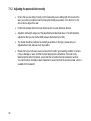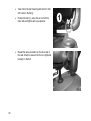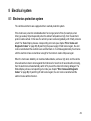
1
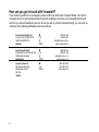
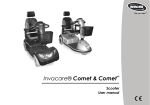
Yes, You Can.® Invacare® Pegasus Scooter Operating manual How can you get in touch with Invacare®? If you have any questions or need support, please contact your authorised Invacare® Dealer, who has the necessary know-how and equipment plus the special knowledge concerning your Invacare® product, and can offer you all-round satisfactory service. Should you wish to contact Invacare® directly, you can reach us in Europe at the following addresses and phone numbers. 2 Invacare Au stralia Pt y Ltd 1 Lenton Place (PO Box 5002) North Roc ks NSW 2151 Australia : Fax: @: WWW: 1800 460 460 02 8839 5353 sales@invac are.c om.au www.invac are.com.au Invacare New Z ealand 4 Westfiel d Plac e (PO Box 62-124) Mt Wellington Auc kl and New Zealand : Fax: @: WWW: 0508 468 222 0508 807 788 sales@invac are.c o.nz www.invac are.co.nz Invacare Canad a L.P. 570 Matheson Bl vd Eas t Mississauga, Ontario L4Z 4G4 Canada : Fax: WWW: 1-800- 668- 5324 1-800- 950- 3176 www.invac are.ca Table of Contents Chapter 1 Introduction 1.1 1.2 1.3 1.4 1.5 2 5 6 20 21 Getting in and out.......................................................................................................... 21 Before driv ing for the first time...................................................................................... 22 Taking Obstacles........................................................................................................... 23 Driv ing up and dow n gradients ..................................................................................... 24 Parking and stationary .................................................................................................. 24 Pushing the scooter by hand 5.1 12 General safety notes...................................................................................................... 12 Safety information w ith regard to care and maintenance.............................................. 15 Safety information on electromagnetic interference...................................................... 16 Safety information on driv ing and freewheel mode....................................................... 17 Key features Driving 4.1 4.2 4.3 4.4 4.5 6 Guarantee........................................................................................................................ 7 Important symbols in this manual ................................................................................... 8 Important symbols found on the v ehicle ....................................................................... 10 Type classification and permissible use........................................................................ 11 Life expectancy ............................................................................................................. 11 Safety notes 2.1 2.2 2.3 2.4 3 4 Page 25 Disengaging Motors ...................................................................................................... 25 Operating Console 26 3 6.1 6.2 6.3 6.4 6.5 6.6 7 Adjustment facilities 7.1 7.2 7.3 7.4 7.5 7.6 7.1 8 8.2 39 Mov ing the seat position forw ards or backwards.......................................................... 39 Adj usting the armrest w idth.......................................................................................... 40 Adj usting the armrest height......................................................................................... 41 Adj usting backrest angle............................................................................................... 42 Disengaging the seat to rotate it or remove it................................................................ 43 Adj usting the seat height manually............................................................................... 44 Postural belts ................................................................................................................ 45 7.1.1 Types of postural belts......................................................................................... 45 7.1.2 Adjusting the postural belt correctly....................................................................... 46 7.1.3 Fixing the containment belt to the scooter.............................................................. 47 Electrical system 8.1 4 Operating Console Arrangement................................................................................... 26 6.1.1 Status Display ..................................................................................................... 27 6.1.2 Battery Charge Display ........................................................................................ 27 Driv ing the Scooter........................................................................................................ 28 Activ ating and Deactivating Acoustic Signals............................................................... 29 Activ ating and Deactivating Speed Reduction During Bend Trav el............................... 33 Diagnosis and fault repair ............................................................................................ 34 6.5.1 Error diagnosis .................................................................................................... 35 Error Codes and Diagnostic Codes............................................................................... 36 49 Electronics protection system....................................................................................... 49 8.1.1 The main fuse...................................................................................................... 50 Batteries........................................................................................................................ 50 8.2.1 What you need to know about batteries................................................................. 50 8.2.2 Charging the batteries.......................................................................................... 52 8.2.3 Removing and fitting batteries............................................................................... 54 8.2.3.1 Removing the batteries.................................................................................... 55 8.2.3.2 How to handle damaged batteries correctly....................................................... 57 9 Care and maintenance 10 Repair Instructions 10.1 58 60 Repairing a flat tire ....................................................................................................... 60 10.1.1 Mending punctures (pneumatic tires of type 4.10 / 3.50 - 5)................................... 61 10.1.1.1 Repairing punctured tires................................................................................ 62 11 Disposal 12 Technical specifications 13 Inspections Performed 64 65 68 5 1 Introduction Dear user, First we would like to thank you for purchasing our product! We hope you will enjoy your new Scooter. This manual contains important hints and information on: Safety Operation Care and maintenance. Please take care to read the operating manual thoroughly before starting out on your first j ourney. This product has been designed to fit the needs of different types of users with different requirements. The decision whether the model is suitable for the user may only be taken by medical specialists with appropriate aptitude. Invacare® or their statutory representatives can accept no liability in cases in which the mobility product has not been adapted to suit the user's handicaps. Some maintenance and settings can be carried out by the user. Certain adjustments do however require technical training and may only be carried out by your Invacare® specialist dealer. Damages and errors caused by nonobservance of the operating manual or as a result of incorrect maintenance are excluded from all guarantees. 6 This manual contains copyrighted information. It may not be reproduced or copied in whole or in part without the prior written consent of Invacare® or its authorised representative. It may also contain information that pertains to models sold only in certain countries. In this case the information will be clearly marked as pertaining to a particular country-specific version. We reserve the right to make any alterations on the grounds of technical improvements. 1.1 Guarantee The terms and conditions of the guarantee are part of the general terms and conditions particular to the individual countries in which this product is sold. 7 1.2 Important symbols in this manual General risks This symbol warns you of general hazards! Always follow the instructions to avoid injury to the user or damage to the product. EXPLOSION HAZARD! This symbol warns you of an explosion hazard, w hich can be caused by excessive tire pressure in a pneumatic tire. Always follow the instructions to avoid injury to the user or damage to the product. BURN HAZARD! This symbol warns you of the danger of chemical burns, for example due to the discharge of battery acids! Always follow the instructions to avoid injury to the user or damage to the product. BURN Risk! This symbol warns of the risk of burns, for example, as a result of hot motor surfaces. Follow the instructions in order to avoid injury or damage to the product. RISK OF CRUSHING! This symbol warns of a risk of crushing caused by being careless w ith heav y components. Always follow the instructions to avoid injury to the user or damage to the product. 8 Wear eye protection This symbol refers to the requirement for w earing eye protection, for example w hen w orking w ith batteries. You must wear safety goggles when this symbol is displayed. Wear protective gloves This symbol indicates the requirement to wear protective gloves, for example w hen w orking w ith batteries. You must wear protective gloves when this symbol is displayed. NOTE: This symbol identifies general information which is intended to simplify working with your product and which refers to special functions. Requirements: This symbol identifies a list of various tools, components and items which you will need in order to carry out certain work. Please do not attempt to carry out the work if you do not have the listed tools available. READ WELL BEFORE OPERATION! This symbol advises you to read information carefully. 9 1.3 Important symbols found on the vehicle This product has been supplied from an env ironmentally aware manufacturer. This product may contain substances that could be harmful to the environment if disposed of in places (landfills) that are not appropriate according to legislation. The 'crossed out wheelie bin' symbol is placed on this product to encourage you to recycle wherever possible. Please be environmentally responsible and recycle this product through your recycling facility at its end of life. 10 1.4 Type classification and permissible use This vehicle was designed for persons whose ability to walk is impaired, but who are still in terms of their eyesight and physically and mentally able to operate an electric vehicle. It has been classified according to EN 12184 as a class B mobility product (for indoor and outdoor areas). It is therefore compact and agile enough for indoor areas, but also able to overcome many obstacles in outdoor areas. You can find exact information on speed, turning radius, range, safe climbing ability, maximum obstacle height and permissible operating conditions in chapter "Technical Specifications" starting from page 46. Please also pay attention to all safety information in chapter "Safety Notes" starting from page 12. The vehicle was successfully tested according to German and international standards as to its safety. It satisfies the requirements according to DIN EN 12184 including EN 1021-1/-2. It was also tested successfully according to EN60529 IPX4 as to its resistance to spray water, and is therefore well suited for typical middle European weather conditions. When equipped with an appropriate lighting system, the vehicle is suitable for use on public roads. 1.5 Life expectancy We estimate a life expectancy of five years for this product, provided it is used in strict accordance with the intended use as set out in this document and all maintenance and service requirements are met. The estimated life expectancy can be exceeded if the product is carefully used and properly maintained, and provided technical and scientific advances do not result in technical limitations. The life expectancy can also be considerably reduced by extreme or incorrect usage. The fact that we estimate a life expectancy for this product does not constitute an additional warranty. 11 2 Safety notes READ WELL BEFORE OPERATION! 2.1 General safety notes Danger of inj ury if this scooter is used in any other w ay than the purpose described in this manual! Adhere strictly to the instructions in this user manual! Danger of inj ury if the scooter is driven w hen your ability to driv e is impaired by medication or alcohol! Never drive any vehicle under the influence of medication or alcohol! Danger of damage or inj ury if the scooter is accidentally set into motion! Switch the power system off before you get in, get out or handle awkward objects! Be aware that the motor brakes are automatically deactivated when the motors are disengaged. For this reason, freewheel operation is only recommended on flat surfaces, never on gradients. Never leave your vehicle on a gradient with its motors disengaged. Always reengage the motors immediately after pushing the vehicle. 12 Danger of inj ury if the On/Off Button is pressed w hile the vehicle is in motion, due to it coming to an abrupt, sharp stop! If you have to brake in an emergency, simply pull the handbrake until the scooter comes to a halt! Only switch the vehicle off while in motion as a last resort! Danger of inj ury if the scooter is transported in another vehicle w ith the occupant seated in it! Never transport the scooter with the occupant seated in it! Danger of inj ury if maximum permissible load is exceeded! Do not exceed the maximum permissible load (see "Technical Specifications" on page 65)! Danger of inj ury w hen lifting heav y components! When maintaining, servicing or lifting any part of your scooter, take into account the weight of the individual components, especially the batteries! Be sure at all times to adopt the correct lifting posture and ask for assistance if necessary! Danger of inj ury if you fall off the scooter! If restraining systems are installed (such as seat belts), use them each time you drive the scooter. 13 Danger of inj ury by mov ing parts! Make sure that no injury is incurred by moving parts of the scooter, like wheels or a Seat Lifter, especially when children are around! Danger of fire or breaking dow n due to electric dev ices being connected! Do not connect any electric devices to your vehicle that are not expressly certified by Invacare® for this purpose! Have all electrical installations done by your authorised Invacare® Dealer! Danger of technical failure and inj ury if unauthorised spare parts and components are used! Only use original Invacare® spare parts, which have been approved for use with this vehicle! 14 2.2 Safety information with regard to care and maintenance Danger of accident and loss of guarantee if maintenance is insufficient! For reasons of safety and in order to avoid accidents which result from unnoticed wear, it is important that this electric mobility product undergoes an inspection once every year under normal operating conditions (see inspection plan contained in service instructions). Under difficult operating conditions such as daily travel on steep slopes, or in the case of use in medical care cases with frequently changing wheelchair users, it would be expedient to carry out intermediate checks on the brakes, accessories and running gear. If the mobility product is to be operated on public roads, the vehicle driver is responsible for ensuring that it is in an operationally reliable condition. Inadequate or neglected care and maintenance of the mobility product will result in a limitation of the manufacturer's liability. 15 2.3 Safety information on electromagnetic interference This electric vehicle was successfully tested in accordance with International standards as to its compliance with Electromagnetic Interference (EMI) Regulations. However, electromagnetic fields, such as those generated by radio and television transmitters, and cellular phones, can influence the functions of electric vehicles. Also, the electronics used in our vehicles can generate a low level of electromagnetic interference, which however will remain within the tolerance permitted by law. For these reasons we ask you to please observe the following precautions: WARNING: Danger of malfunction due to electromagnetic interference! Do not switch on or operate portable transceivers or communication devices (such as radio transceivers or cellular phones) when the vehicle is switched on. Avoid getting near strong radio and television transmitters. In case the vehicle should be set in motion unintentionally or the brakes are released, switch it off immediately. Adding electrical accessories and other components or modifying the vehicle in any way can make it susceptible to electromagnetic interference. Keep in mind that there is no sure way to determine the effect such modifications will have on the overall immunity of the electronic system. Report all occurrences of unintentional movement of the vehicle, or release of the electric brakes to the manufacturer. 16 2.4 Safety information on driving and freewheel mode Danger of inj ury if the vehicle tips ov er! Only ever negotiate gradients up to the maximum tilt-resistant gradient and only with the backrest in an upright position, and the seat lifter in the lowest position (if installed)! Only ever drive downhill at a maximu m of 2/3rds of the top speed! Avoid abrupt braking or accelerating on gradients! If at all possible, avoid driving on slippery surfaces (such as snow, gravel, ice etc.) where there is a danger of you losing control over the vehicle, especially on a gradient! If driving on such a surface is inevitable, then always drive slowly and with the utmost caution! Never attempt to overcome an obstacle when on an uphill or downhill gradient! Never attempt to drive up or down a flight of steps! Always approach obstacles straight on! Ensure that the front wheels and rear wheels move over the obstacle in one stroke, do not stop halfway! Do not exceed the maximu m obstacle height (see "Technical Specifications" on page 65)! Avoid shifting your centre of gravity as well as abrupt changes of direction when the vehicle is in motion! 17 Danger of inj ury if the vehicle tips ov er! (Continued) Never use the vehicle to transport more than one person! Do not exceed the maximum permissible load! When loading the vehicle, always distribute the weight evenly! Always try to keep the centre of gravity of the vehicle in the middle, and as close to the ground as possible! Note that the vehicle will brake or accelerate if you change the Driving Speed while it is in motion! Danger of inj ury if you collide w ith an obstacle w hen driving through narrow passages such as doorw ays and entrances! Drive through narrow passages in the lowest Driving Speed and with due caution! CAUTION: The centre of gravity for the scooter is higher than that of an electric w heelchair! There is an increased tipping hazard w hen negotiating bends! Reduce speed before negotiating bends! Only accelerate when you have come out of the bend! CAUTION: Danger of tipping! Anti tip w heels (stabilisers) are only effective on firm ground! They sink in on soft ground such as grass, snow or mud if the electrical vehicle rests itself on them. They lose their effect and the electrical vehicle can tip over. Only drive with extreme care on soft ground, especially during uphill and downhill journeys. In the process pay increased attention to the tip stability of the electric vehicle. 18 CAUTION: it may be difficult to turn in front of a lift or building entrance because the scooter turning circle may not necessarily comply w ith building standards! Always be aware of the limitations of your scooter, particularly the turning circle capabilities when entering a building or a lift. Avoid driving situations in which you would no longer be able to come out because you cannot turn your scooter around! 19 3 Key features 20 1) Disengaging lever 2) Unlocking lever for sliding seat rails (front right below seat) 3) Unlocking lever for swivelling and removing seat (left under the seat, not visible in picture) 4) Operating console 5) Brake lever (right-hand lever) 6) Lever for adjusting steering column inclination (left-hand lever, not visible in picture). 7) Keyswitch (ON/OFF) 4 Driving 4.1 Getting in and out The armrests can be swivelled upwards to assist getting in and out. The seat can also be rotated to assist getting in and out. Lift the detent lever (1) up. Turn the seat to the side. Information on turning the seat The detent automatically engages again after 45°. 21 4.2 Before driving for the first time... Before you take your first trip, you should familiarise yourself well with the operation of the vehi cle and with all operating elements. Take your time to test all functions and driving modes. NOTE: If installed, make sure to properly adjust and use the postural belt each time you use the wheelchair. Sitting Comfortably = Driving Safely Before each trip, make sure that: 22 You are w ithin easy reach of all operating controls. The battery charge is sufficient for the distance intended to be covered. The postural belt (if installed) is in perfect order. The rear mirror (if installed) is adj usted so you can look behind at all times without hav ing to bend forw ard or shift your seating position. 4.3 Taking Obstacles Your Scooter can climb obstacles and kerbs of up to 6 cm in height. CAUTION: Danger of Tipping Ov er! Never approach obstacles at an angle but at 90 degrees as shown below. Put your backrest into an upright position before climbing an obstacle. Driv ing up over an obstacle Approach the kerb or obstacle slowly head-on. Shortly before the front wheels touch the obstacle, increase the speed and reduce only after the rear wheels have also climbed the obstacle. Driv ing dow n off of an obstacle Approach the kerb or obstacle slowly head-on. Before the front wheels touch the obstacle, reduce speed and keep it until also the rear wheels have come down off of the obstacle. Correct Incorrect 23 4.4 Driving up and down gradients For information concerning the maximum safe slope, please see chapter "Technical Specifications" starting on page 65. WARNING: Danger of tipping ov er! Only ever drive downhill at a maximu m of 2/3rds of the top speed! Always return the backrest of your seat to an upright position before ascending slopes! We recommend that you lean the backrest slightly to the rear before descending slopes! Never attempt to ascend or descend a slope on slippery surfaces or where there is a danger of skidding (such as wet pavement, ice etc)! Avoid trying to get out of the vehicle on an incline or a gradient! Always drive in a straight direction along the road or path you are travelling on, rather than attempting to zigzag! Never attempt to turn around on an incline or a slope! 4.5 Parking and stationary If you park your v ehicle, or leave it at a standstill for a longer period: switch off the power supply (keyswitch). 24 5 Pushing the scooter by hand The motors of the scooter are equipped with automatic brakes, preventing the scooter from rolling away out of control when the power supply is switched off. When pushing the scooter, the magnetic brakes must be disengaged. 5.1 Disengaging Motors Danger of the vehicle running aw ay! When the motors are disengaged (for push operation whilst freewheeling), the electromagnetic motor brakes are deactivated! When the vehicle is parked, the levers for engaging and disengaging the motors must without fail be locked firmly into the "DRIVE" position (electromagnetic motor brakes activated)! The lev er for engaging and disengaging the motor is located on the right-hand side at the rear. Disengaging the drive Switch off the Scooter (keyswitch). Press the unlocking knob on the disengaging lever (1). Push the disengaging lever forwards. The drive is now disengaged. Engaging the drive Pull the lever to the rear. 25 6 Operating Console 6.1 Operating Console Arrangement 1) Status display 2) Speed controller 3) Switching speed reduction during bend travel on and off 4) Horn 5) Left-hand direction indicator (switches itself off automatically after 30 seconds) 6) Battery charge display 7) Speed reduction 8) Warning blinker 9) Right-hand direction indicator (switches itself off automatically after 30 seconds) 10) Lighting 11) Driv e lev er 26 6.1.1 Status Displa y NOTE: The ON/OFF diode is used as a fault display (status display). Chapter "Error Codes and Diagnostic Codes" on page 26 contains an explanation of the error codes. 6.1.2 Battery Charge Display All diodes illuminate: maximum driving range Only red and yellow diodes illuminate: reduced driving range. Recharge the batteries at the end of your journey. Only red LEDs illuminate/blink, electronics beeps 3x: battery reserve = severely restricted driving range. Recharge batteries immediately! NOTE: Overdischarge protection: after a certain drive time on reserve battery power the electronics system switches the drive off automatically and brings the Scooter to a standstill. If you do not drive your Scooter for a while the batteries will "recuperate" and allow a further, but short, journey. However, after a very brief journey the red diodes will illuminate again and the electronic system will beep three times. This procedure leads to battery damage and should be avoided if possible! 27 6.2 Driving the Scooter WARNING: Danger from the unintended rolling of the vehicle! When stopping the v ehicle, the drive lever needs to return entirely to the middle position to activ ate the electromagnetic brakes. If there is any obstruction stopping the lev er from returning to the middle position, the electromagnetic brakes cannot be activated. This can lead to the vehicle rolling unintentionally. Please make sure that the drive lever is in the middle position, if the vehicle is to remain stationary. Switch the power supply on (keyswitch) The operating console display illuminates. The Scooter is ready to drive. NOTE: If the Scooter is not ready to drive after switching on, check the status display (see Chapter "Status Display" on page 27 and Chapter "Diagnosis and fault repair" on page 34. Set the required speed with the speed controller. Pull the right-hand drive lever carefully to travel forwards. Pull the left-hand drive lever carefully to travel in reverse. NOTE: The control system is programmed with standard values in the works. Your Invacare®dealer can carry out programming tailored to fit your requirements. 28 CAUTION: any changes to the drive program can affect the driving characteristics and the tipping stability of the v ehicle! Changes to the drive program may only be carried out by trained Invacare® specialist dealers! Invacare® supplies all mobility products with a standard drive program ex-works. Invacare® can only give a warranty for safe vehicle driving behaviour - especially the tipping stability for this standard drive program! NOTE: To brake quickly, simply let go of the driving lever. It will automatically return to the middle position. The scooter will brake. To brake in an emergency, follow the above and pull the handbrake lever until the scooter comes to a halt. 6.3 Activating and Deactivating Acoustic Signals The Scooter electronic system can be programmed to emit an acoustic signal in the following situations: battery capacity low (activated in delivery status) direction indicators actuated (activated in delivery status) hazard lamps actuated (activated in delivery status) Reverse gear activated (both reverse gear and the acoustic signal are activated in delivery status) 29 The electronic system must be switched off in order to activate or deactivate an acoustic signal for particular functions, and a particular keystroke combination needs to be entered when switching on again. After a signal for a particular function has been successfully activated/deactivated, a combination of LEDs on the battery charge display will blink as a confirmation. The LEDs are numbered as shown on the right: 30 The keystroke combinations and LED codes for various options are as follows: Function: Keystroke combination Acoustic signal at "Lighting" + "direction low battery capacity indicator left" Acoustic signal when direction indicators actuated "Lighting" + "direction indicator right" LED(s) Condition D1 deactivated D1+D2 activated D3 deactivated D3+D4 activated Acoustic signal "Lighting" + "hazard lamps" D5 when hazard lamps actuated D5+D6 deactivated Acoustic signal when reverse gear actuated D1+D2+D3 deactivated D4+D5+D6 activated 'Lighting' + 'Button 3' (see "Operating Console Arrangement" on page 26) activated 31 Activ ating or deactivating an acoustic signal Please proceed as follows to activate or deactivate an acoustic signal for a particular function: 1) Switch off the electronic system. 2) Enter the keystroke combination and hold. 3) Switch on the electronic system 4) Wait two seconds until the appropriate blink code is displayed on the battery charge display, then release the keys. Do not hold the keystroke combination down for more than five seconds. 5) If LED D7 blinks five times subsequently the acoustic signal has been successfully activated. 6) The electronic system will return to normal operating status automatically. 32 6.4 Activating and Deactivating Speed Reduction During Bend Travel Your Scooter is fitted with automatic speed reduction which is activated as standard when the Scooter is switched on. This function lowers the Scooter's speed as soon as you start driving round a bend. It is primarily designed for inexperienced users who may feel unsure of the Scooter's dynamic driving behaviour in a bend. If, however, you are an experienced user, you may wish to deactivate this function. Deactivating speed reduction Press key (1) for more than two seconds. The LED (2) illuminates. Speed reduction is deactivated. Activ ating speed reduction Press key (1) for more than two seconds. The LED (2) goes out. Speed reduction is activated again. 33 6.5 Diagnosis and fault repair The electronic system offers diagnostic information to support the technician during the recognition and rectification of faults on the Scooter. If there is a fault, the status display blinks several times, pauses, then blinks again. The type of fault is displayed by the number of blinks in each group, which are also known as the "blink code". The electronic system reacts differently depending on the seriousness of the fault and its effect on user safety. It can, for example: simply show the blink code as a warning and allow both driving and normal operation to continue; display the blink code, stop the Scooter and prevent further travel until the electronic system has been switched off and switched on again; display the blink code, stop the Scooter and not permit further travel until the fault has been rectified. You can find detailed descriptions of individual blink codes, including possible causes and fault repair, in the section entitled "Error Codes and Diagnostic Codes" on page 36. 34 6.5.1 Error diagnosis If the Scooter shows a failure, please use the following guide to locate the fault. NOTE: Before making any diagnosis, ensure that the Scooter has been switched on at the keyswitch. If the status display is OFF: check w hether the keysw itch is SWITCHED ON. Check w hether all cables are correctly connected. If the status bar indicator is BLINKING: count the number of blinks and then proceed to the next section. 35 6.6 Error Codes and Diagnostic Codes Blink code 1 2 3 Fault Consequence for the Scooter Battery must be Continues to charged drive Battery voltage too Stops driving low Battery voltage too Stops driving high 36 Comments The batteries are discharged. Charge the battery as soon as possible. The batteries are depleted. Charge batteries. If you switch the Scooter off for a few minutes, the battery can often recuperate to such a stage that a short journey is still possible. The battery voltage is too high. If the battery charger is connected, disconnect it from the Scooter. The electronic system charges the batteries when running downhill and when braking. This fault is caused when the battery voltage becomes too high during this process. Switch the Scooter off and on again. Blink code 4 Fault Power time exceeded Consequence for the Scooter Stops driving 5 Brake failure Stops driving 6 No neutral position Stops driving when switching Scooter on. Comments The maximum current was exceeded over too long a period, probably because the motor was overloaded or has been working against an immovable resistance. Switch the scooter off, wait a few minutes and then switch on again. The electronic system has determined a motor short-circuit. Check the wiring harness for short-circuit and check the motor. Contact your Invacare® dealer. Ensure that the disconnection lever is pressed in. There is a defect in the braking coil or in the cabling. Check the magnetic brake and cabling for open or short-circuited circuitry. Contact your Invacare® dealer. Drive lever is not in neutral when the keyswitch was turned. Put the drive lever in neutral, turn the power off and then turn on again. It may be necessary to recalibrate the drive lever. Contact your Invacare® dealer. 37 Blink code 7 Fault Fault in speed potentiometer Consequence for the Scooter Stops driving 8 Motor voltage error Stops driving 9 Miscellaneous internal fault Push/freewheel mode error Stops driving Stops driving 10 38 Comments The drive lever electronics could be faulty or incorrectly connected. Check the cabling for open or short-circuited circuitry. Potentiometer is not correctly adjusted. Put the potentiometer into the centre position. The motor or its cabling is defective Check the cabling for open or shortcircuited circuitry. Contact your Invacare® dealer. The Scooter has exceeded the permissible maximum speed during pushing or freewheeling. Switch the electronics system off and on again. 7 Adjustment facilities 7.1 Moving the seat position forwards or backwards The disengaging lever for adjusting the seat is located front right below the seat Pull the lever (1) to disengage the seat. Slide the seat forwards or backwards into the required position. Let go the lever again to lock the seat into its required position. 39 7.2 Adjusting the armrest width The hand wheels for releasing the armrests are located under the seat (1). 40 Turn the hand wheels to loosen the fixing for the armrest. Adjust the armrests to the required width. Retighten the handwheels 7.3 Adjusting the armrest height Requirements: Phillips screwdriver Use the screwdriver to loosen and remove the armrest fixing screw. Adjust the armrests to the required height. Reposition the screw and tighten again. 41 7.4 Adjusting backrest angle The lever (1) for adjusting the backrest angle is located on the right of the seat. 42 Pull the lever and adjust the backrest to the required angle by leaning forwards or backwards. 7.5 Disengaging the seat to rotate it or remove it The seat can be turned to one side to make getting in and out of the scooter easier. The seat is also easier to remove from this position. The lever for disengaging the seat is located under the seat (1) on the left. Pull the lever forwards to disengage the seat. Turn the seat to one side. If you want to remove the seat, hold it firmly by the backrest and front edge and remove it upwards. 43 7.6 Adjusting the seat height manually Requirements: 2x open-ended spanners 17 mm 44 Remove the seat Remove the battery and motor compartment cover. Remove the seat pillar locking bolt using both open-ended spanners. Adjust the seat height. Reinsert the bolt and tighten. 7.1 Postural belts A postural belt is an option which can either be fixed to the wheelchair ex-works or can be retrofitted by your specialist dealer. If your wheelchair is fitted with a postural belt, your specialist dealer will have informed you about fitting and usage. The postural belt is used to help the wheelchair user keep an optimum sitting position. Correct use of the belt assist s the user in sitting securely, comfortably and well-positioned in the wheelchair, especially for such users who do not have such a good sense of balance while sitting. NOTE: We recommend using the postural belt whenever the wheelchair is used. The belt should be tight enough to ensure that you are sitting comfortably and that your body is in the correct sitting position. 7.1.1 Types of postural belts Your wheelchair can be fitted with the following postural belt types ex-works. If your wheelchair has been fitted with a different belt to those listed below, please ensure that you have received the manufacturer's documentation with regard to correct fitting and use. Belt w ith metal buckle adj ustable on one side The belt can only be adjusted on one side, which can result in the buckle not being in the middle of the waist (across pelvic area) after adjustment has taken place. 45 7.1.2 Adjusting the postural belt correctly 46 Ensure that you are sitting correctly, which means that you are sitting right at the back of the seat, your pelvis is positioned erect and as symmetrically as possible, not to the front, to the side or at one edge of the seat. Position the postural belt so that your hipbones can be easily felt above the belt. Adjust the belt length using one of the adjustment aids described above. The belt should be adjusted so that you can fit a flat hand between the belt and your body. The buckle should be positioned as centrally as possible. In doing so, please carry out adjustments on both sides as much as possible. Please check your belt every week to ensure that it is still in good working condition; to ensure it has no damage or wear, and that it is fixed properly to the wheelchair. If the belt is only fastened with a bolted connection, ensure that the connection has not loosened or undone. You can find more information about maintenance work on belts in the service manual, which is available from Invacare®. 7.1.3 Fixing the containment belt to the scooter Requirements: jaw spanner 12 mm jaw spanner 13 mm The fixing points (1) for attaching the belt are located under the seat (the figure shows only the left hand side). 47 48 Take hold of the belt mounting and hold it in front of the hole in the fixing. Position the bolt (1), screw the nut on from the other side and tighten with a jaw spanner. Repeat the same procedure on the other side of the seat. Check to ensure that the nut is tightened properly on the bolt. 8 Electrical system 8.1 Electronics protection system The vehicle's electronics are equipped with an overload-protection system. If the motors are put under considerable strain for a longer period of time (for example, when driving up a steep hill) and especially when the ambient temperature is high, then the electronic system could overheat. In this case the vehicle's power is reduced gradually until it finally comes to a halt. The Status Display shows a corresponding error code (see chapter "Error Codes and Diagnostic Codes" on page 36). By switching the power supply off and back on again, the error code is cancelled and the electronics are switched back on. It will take approximately five minutes until the electronics have cooled down enough for the motors to restore full power again. When the motors are stalled by an insurmountable obstacle, such as a high kerb, and the vehicle driver allows the motors to strain against this hindrance for more than 20 seconds without moving, then the electronics will automatically switch off to prevent the motors from being damaged. The Status Display shows a corresponding error code (see chapter "Error Codes and Diagnostic Codes" on page 36). By switching off and back on again, the error code is cancelled and the electronics are switched back on. 49 8.1.1 The main fuse The entire electric system is protected against overload by two master fuses. The master fuses are mounted on the positive battery cables. NOTE A defective main fuse may be replaced only after checking the entire electric system. An Invacare® specialised dealer must perform the replacement. You can find information on the fuse type in chapter "Technical Specifications" starting on page 65. 8.2 Batteries 8.2.1 What you need to know about batteries Power is supplied by two 12 V batteries. The batteries are maintenance-free and only need regular charging. New batteries should always be fully charged once before their first use. New batteries will be at their full capacity after having run through approx. 10 - 20 charging cycles. How fast the batteries discharge depends on many circumstances, such as ambient temperature, condition of the surface of the road, tire pressure, weight of the driver, way of driving and utilisation of lighting. 50 NOTE The batteries supplied with your electric vehicle are not hazardous goods. This classification is based on the German GGVS Hazardous Goods Road Transport Ordinances, and the IATA/DGR Hazardous Goods Rail Transport / Air Transport Ordinances. Batteries may be transported without restrictions, whether by road, rail or by air. Individual transport companies have, however, guidelines which can possibly restrict or forbid certain transport procedures. Please ask the transport company regarding each individual case. Pay attention to the Battery Charge Indicator! Make sure to charge the batteries when the Battery Charge Indicator shows that battery charge is low. We recommend charging the batteries after each trip, as well as each night over night. Depending on the level of discharge, it can take up to 12 hours until the batteries are fully charged again. Protect your charger from sources of heat such as heaters and direct sunlight. If the battery charger overheats, charging current will be reduced and the charging process delayed. To avoid damaging the batteries, never allow them to be fully discharged. Do not drive on heavily discharged batteries if it is not absolutely necessary, as this will strain the batteries unduly and shorten their life expectancy. In case your vehicle is not used for a longer period of time, then the batteries must be charged at least once a month to maintain a full charge. Alternatively, the vehicle can stay connected to the charger. The batteries cannot be overcharged with the specified charger. Please use only charging devices in Class 2. This class of chargers may be left unattended during charging. All charging devices which are supplied by Invacare® comply with these requirements. 51 8.2.2 Charging the batteries Make sure you read and understand the battery charger's User' s Manual, if supplied, as well as the safety notes on the front and rear panels of the charger! WARNING: Danger of explosion and destruction of batteries if the w rong battery charger is used! Only ever use the battery charger supplied with your vehicle, or a charger that has been approved by Invacare®. Danger of electric shock and damage to the battery charger if it is allowed to get wet! Protect the battery charger from water. Always charge in a dry environment. Danger of short circuit and electric shock if the battery charger has been damaged! Do not use the battery charger if it has been dropped or damaged. Danger of fire and electric shock if a damaged extension cable is used! Only ever use an extension cable if it is absolutely necessary. In case you must use one, make sure it is in good condition. 52 The charging socket is located on the left of the steering column Connecting the battery charger Switch off the Scooter. Push the protective cap on the side of the charging socket to the side. Connect the battery charger to the Scooter. Connect the battery charger to the mains. Disconnecting the battery charger from the Scooter First unplug the battery charger from the mains. Then unplug the battery charger from the Scooter. 53 8.2.3 Removing and fitting batteries WARNING: Danger of inj ury if the batteries are not handled correctly during assembly and maintenance w ork! New batteries should be installed by authorised technicians! Observe the warnings on the batteries! Take into account the heavy weight of the batteries! Only ever use the battery type defined in the technical specifications (see "Technical Specifications" on page 65)! Danger of fire and burns if battery terminals are short-circuited! DO NOT short-circuit battery terminals with a tool! WARNING: Corrosion and burns from acid leakage if batteries are damaged! Remove clothes that have been soiled by acid immediately. After contact w ith skin: Immediately wash affected area with lots of water. After contact w ith eyes: Immediately rinse eyes under running water for several minutes; consult a physician. 54 8.2.3.1 Remov ing the batteries Requirements: Open spanner, 11 mm. Remove the seat. Remove the battery and motor compartment cover. Open the battery retaining strap (1). Unplug the battery connecting plug (2). Remove the batteries. 55 Loosen the blue cable on the negative battery terminal with the open-ended spanner, and remove the cable. Loosen the red cable battery clamp on the positive battery terminal with the open-ended spanner, and remove the cable. Repeat the procedure for the other battery NOTE: Replacing new batteries takes place in reverse order. 56 8.2.3.2 How to handle damaged batteries correctly WARNING: Corrosion and burns from acid leakage if batteries are damaged! Remove clothes that have been soiled by acid immediately. After contact w ith skin: Immediately wash affected area with lots of water. After contact w ith eyes: Immediately rinse eyes under running water for several minutes; consult a physician. Always wear safety goggles and appropriate safety clothing when handling damaged batteries. Place damaged batteries in an acid-resistant receptacle immediately after removing them. Only ever transport damaged batteries in an appropriate acid-resistant receptacle. Wash all objects that have come into contact with acid with lots of water. Disposing of dead or damaged batteries correctly Dead or damaged batteries can be given back to your dealer or directly to Invacare®. 57 9 Care and maintenance NOTE: Have your vehicle checked once a year by an authorised Invacare® dealer in order to maintain it's driving safety and roadworthiness. Cleaning the vehicle When cleaning the vehicle, pay attention to the following points: Only use a damp cloth and gentle detergent. Do not use any abrasive or scouring liquids. Do not subject the electronic components to any direct contact with water. Do not use high-pressure cleaning devices. Disinfection Spray or wipe disinfection using a tested and recognised product is permitted. A list of the current permitted disinfectants is available from the Robert Koch Institute at http://www.rki.de. 58 Seat and backrest padding: Check for perfect condition. Tires: Have tires checked for specified air pressure (2,5 bar). Front w heels Front wheels must spin smoothly. If wheels wobble or do not spin easily, adjust steering pivot pin or front wheel bearing. Rear w heels: Test wheel for firm seat on the axle drive shaft. Rear wheels must spin without wobbling Electronics / Electrical System: Check all plug connections for condition and firm connection. Have batteries been fully charged before the daily operation? Are all holders, screws firmly fixed, tight and safe? Are all electric bulbs of the lighting system (if applicable) in working order? Cleaning: Clean all parts carefully. Monthly Weekly When Delivered Maintenance Jobs Before every trip Before each trip When necessary Once a year you should have your vehicle inspected and serv iced by your authorised dealer. A complete checklist of necessary maintenance w ork can be found in the Service Manual, w hich can be obtained from Invacare®. 59 10 Repair Instructions The following are instructions on repairs that can be performed by the user. For the specifications of spare parts please see "Technical Specifications" on page 65, or consult the Service Manual, available from Invacare® (in this connection please see the addresse s and phone numbers in section "How can you get in touch w ith Invacare®?" on page 2). In case you require assistance, please contact your Invacare® Dealer. 10.1 Repairing a flat tire WARNING: Danger of damage or inj ury if the v ehicle is accidentally set into motion during repairs! Switch the power off (ON/OFF Button)! Engage the motors! Secure the vehicle against rolling away by placing wedges under the wheels! 60 10.1.1 Mending punctures (pneumatic tires of type 4.10 / 3.50 - 5) Requirements: Open spanner, 17 mm. Rubber hammer Raise the vehicle and place wooden blocks underneath to support it. Remove the wheel locknut (1) with a 17 mm open-ended spanner. Remove the wheel by tapping it gently with the rubber hammer on the rear face to carefully loosen it from the axle. Problems w hen removing w heel? It may be necessary to use a special tool Please ask your Invacare® dealer to help you. 61 10.1.1.1 Repairing punctured tires Requirements inner tube repair set or a new inner tube talcum powder open-ended spanner, 12 mm 62 Remove valve cap. De-inflate the tire by pressing in the centre valve pin. Loosen the 4 bolts (1) with the socket spanner and remove them. Remove both wheel rim halves out of the tire and remove the inner tube. Repair the inner tube and refit in the wheel, or replace it with a new inner tube. Did the old inner tube get w et during the repair? If you repaired the old inner tube and reused it, and it became wet during repair, it is much easier to refit it into the wheel if you powder it lightly with talcum powder. Refit the wheel rim parts from outside into the tire. Pump up the tire lightly. Reinsert the nuts and bolts which hold the wheel rim together and tighten fully. Make sure that the tire is properly located on the wheel rim. Inflate the tire up to the recommended tire pressure (40 psi). Check to make sure that the tire is still located properly on the wheel rim. Screw the valve cap back on. Locate the wheel on the drive shaft again. Apply the handbrake and hold it there to centre the brake. Tighten the wheel locknut with the handbrake applied. 63 11 Disposal 64 The equipment wrapping is potentially recyclable. The metal parts are used for scrap metal recycling. The plastic parts are used for plastic recycling. Electric components and printed circuit boards are disposed of as electronic scrap. Exhausted or damaged batteries can be returned to your medical equipment supplier or Invacare®. Disposal must be carried out in accordance with the respective national legal provisions. Ask your city or district council for details of the local waste management companies. 12 Technical specifications Permissible operating and storage conditions Temperature range for operation -25° … +50 °C according to ISO 7176-9: Temperature range for storage -40° … +65 °C according to ISO 7176-9: Electrical system Motor Batteries Main fuse Charging dev ice Output current Output voltage Input voltage Operating temperature (surroundings) Storage temperature Tires Tire type Tire pressure 6 km/h: S1: 240 W, Maxpeak 500 W 10 km/h: S1: 240 W, Maxpeak 600 W 12 km/h: S1: 250 W, Maxpeak 1200 W 2 x 12V / 40 Ah (C20) Gel 2 x 12V / 50 Ah (C20) AGM 70 A 8A 24V nominal (12 cells) 200 – 250V nominal -25° ... +50°C -40° ... +65°C 4.10 / 3.50 - 5 pneumatic 2.8 bar 65 Driv ing characteristics Speed Max. safe slope Max. climbable obstacle height Turning radius Drive range in accordance with ISO 7176 *** Dimensions Overall length Drive unit width Overall width (armrest adjustment range) Total height Seat width Seat depth Seat height Backrest angle Armrest height Weight Empty weight 66 6 km/h 10 km/h 12 km/h 3-wheel: 8° 4-wheel: 12° 8 cm 3-wheel: 112.5 cm 4-wheel: 140 cm 42 km 3-wheel: 127 cm 4-wheel: 129 cm 62.5 cm 63 ... 72.5 cm 120 cm 20 inch 18.5 inch 42 / 44.5 / 47 / 49.5 cm 95° ... 140° 21 ... 25.5 cm 3-wheel: 103 kg 4-wheel: 110 kg Loading Max. load Axle loads Max. front axle load Max. rear axle load 136 kg 3-wheel: 67 kg 4-wheel: 75 kg 3-wheel: 171 kg 4-wheel: 170 kg *** Note: T he drive range of an electric wheelchair is strongly influenced by external factors, such as the charging state of the batteries, surrounding temperature, local topography, road surface characteristics, tire pressure, weight of driver, drive style and use of batteries for lighting, servos etc. **** Measured without seat cushion 67 13 Inspections Performed It is confirmed by stamp and signature that all jobs listed in the inspection schedule of the Service and Repair Instructions have been properly performed. The list of the inspection jobs to be performed can be found in the Service Manual which is available through Invacare®. 68 Delivery Inspection 1 st Annual Inspection Stamp of authorised Dealer / Date / Signature Stamp of authorised Dealer / Date / Signature 2 nd Annual Inspection 3 rd Annual Inspection Stamp of authorised Dealer / Date / Signature Stamp of authorised Dealer / Date / Signature 4 th Annual Inspection 5 th Annual Inspection Stamp of authorised Dealer / Date / Signature Stamp of authorised Dealer / Date / Signature Manufacturer: CHIEN TI ENTERPRISE CO. LTD. No. 13, Lane 227, Fu Ying Road Hsin Chuang, Taipei, Taiwan R.O.C. Distribution: Canada Inv acare Canada L.P. 570 Matheson Blvd East Mississauga Ontario L4Z 4G4 Canada Phone: 1-800-668-5324, Fax: 1-800-950-3176 69 LIMITED WARRANTY PLEASE NOTE: THE WARRANTY BELOW HAS BEEN DRAFTED TO COMPLY WITH FEDERAL LAW APPLICABLE TO PRODUCTS MANUFACTURED AFTER JULY 4, 1975. This warranty is extended only to the original purchaser/user of our products. This warranty gives you specific legal rights and you may also have other legal rights which vary from state to state. Invacare warrants all electronics and electrical components (excluding batteries), transaxle and frame to be free from defects in materials and workmanship for a period of twenty four (24) months from the date of purchase from Invacare or a dealer. Invacare warrants all batteries for a period of six (6) months from the date of purchase from Invacare or a dealer. If within such warranty period any such product shall be proven to be defective, such product shall be repaired or replaced at Invacare's option. This warranty does not include any labor or shipping charges incurred in replacement part installation or repair of any such product. Invacare’s sole obligation and your exclusive remedy under this warranty shall be limited to such repair and/or replacement. For warranty service, please contact the dealer from whom you purchased your Invacare product. In the event you do not receive satisfactory warranty service, please write directly to Invacare at the address on the bottom of the back cover. Provide dealer's name address, date of purchase, indicate nature of the defect and, if the product is serialized, indicate the serial number. Do not return products to our factory without our prior consent. 70 LIMITED WARRANTY CONTINUED LIMITATIONS AND EXCLUSIONS: THE FOREGOING WARRANTY SHALL NOT APPLY TO SERIAL NUMBERED PRODUCTS IF THE SERIAL NUMBER HAS BEEN REMOVED OR DEFACED, PRODUCTS SUBJECT TO NEGLIGENCE, ACCIDENT, IMPROPER OPERATION, MAINTENANCE OR STORAGE, COMMERCIAL OR INSTITUTIONAL USE, PRODUCTS MODIFIED WITHOUT INVACARE'S EXPRESS WRITTEN CONSENT INCLUDING, BUT NOT LIMITED TO, MODIFICATION THROUGH THE USE OF UNAUTHORIZED PARTS OR ATTACHMENTS; PRODUCTS DAMAGED BY REASON OF REPAIRS MADE TO ANY COMPONENT WITHOUT THE SPECIFIC CONSENT OF INVACARE, OR TO A PRODUCT DAMAGED BY CIRCUMSTANCES BEYOND INVACARE'S CONTROL, AND SUCH EVALUATION WILL BE SOLELY DETERMINED BY INVACARE. THE WARRANTY SHALL NOT APPLY TO PROBLEMS ARISING FROM NORMAL WEAR OR FAILURE TO ADHERE TO THESE INSTRUCTIONS. A CHANGE IN OPERATING NOISE, PARTICULARLY RELATIVE TO MOTORS AND GEARBOXES DOES NOT CONSTITUTE A FAILURE. ALL SUCH DEVICES WILL EXHIBIT A CHANGE IN OPERATING NOISE DUE TO AGING. THE FOREGOING EXPRESS WARRANTY IS EXCLUSIVE AND IN LIEU OF ANY OTHER WARRANTIES WHATSOEVER, WHETHER EXPRESS OR IMPLIED, INCLUDING THE IMPLIED WARRANTIES OF MERCHANTABILITY AND FITNESS FOR A PARTICULAR PURPOSE, AND THE SOLE REMEDY FOR VIOLATIONS OF ANY WARRANTY WHATSOEVER, SHALL BE LIMITED TO REPAIR OR REPLACEMENT OF THE DEFECTIVE PRODUCT PURSUANT TO THE TERMS CONTAINED HEREIN, THE APPLICATION OF ANY IMPLIED WARRANTY WHATSOEVER SHALL NOT EXTEND BEYOND THE DURATION OF THE EXPRESS WARRANTY PROVIDED HEREIN. INVACARE SHALL NOT BE LIABLE FOR ANY CONSEQUENTIAL OR INCIDENTAL DAMAGES WHATSOEVER. THIS WARRANTY SHALL BE EXTENDED TO COMPLY WITH STATE/PROVINCIAL LAWS AND REQUIREMENTS. 71 English Order No. of this Manual: 10-797C_PEGASUS_ENGLISH.DOC Release Date: 2011-08-15