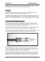
1
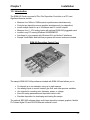
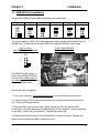
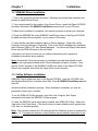
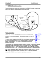
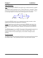
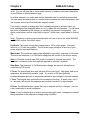
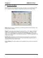
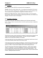
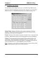
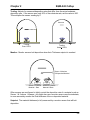
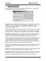
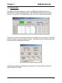
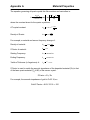
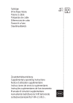
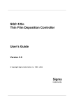
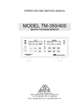
SQM-242
Quartz Crystal Card
SAM-242
Analog Input Card
SQM-242 CoDep
Co-Deposition Control Software
User’s Guide
Version 2.03
© Copyright Sigma Instruments, Inc. 1999 - 2004
Σ
Sigma
instruments
Safety Information
Read this manual before installing, operating, or servicing equipment. Do not install
substitute parts, or perform any unauthorized modification of the product. Return the
product to Sigma Instruments for service and repair to ensure that safety features are
maintained.
Safety Symbols
WARNING: Calls attention to a procedure, practice, or condition that could
possibly cause bodily injury or death.
CAUTION: Calls attention to a procedure, practice, or condition that could
possibly cause damage to equipment or permanent loss of data.
Refer to all manual Warning or Caution information before using this product
to avoid personal injury or equipment damage.
Hazardous voltages may be present.
Earth ground symbol.
Chassis ground symbol.
Equipotential ground symbol.
Warranty Information
Hardware Warranty: This Sigma Instruments product is warranted against defects in
material and workmanship for a period of 2 years from the date of shipment, when used
in accordance with the instructions in this manual. During the warranty period, Sigma
will, at its option, either repair or replace products that prove to be defective.
Software Warranty: Sigma Instruments warrants that the media on which this software
is supplied will be free from defects for a period of 90 days from the date of shipment.
Sigma Instruments does not warrant that 1) the software and any updates will be free
from defects, 2) the software will satisfy all of your requirements, 3) the use of the
software will be uninterrupted or error free.
Limitation of Warranty
Defects from, or repairs necessitated by, misuse or alteration of the product, or any
cause other than defective materials or workmanship are not covered by this warranty.
NO OTHER WARRANTIES ARE EXPRESSED OR IMPLIED, INCLUDING BUT NOT
LIMITED TO THE IMPLIED WARRANTIES OF MERCHANTABILITY AND FITNESS
FOR A PARTICULAR PURPOSE. UNDER NO CIRCUMSTANCES SHALL SIGMA
INSTRUMENTS BE LIABLE FOR CONSEQUENTIAL OR OTHER DAMAGES
RESULTING FROM A BREACH OF THIS LIMITED WARRANTY, OR OTHERWISE.
Return Policy
The purchaser may return this product in new condition within 30 days after shipment
for any reason. In case of return, purchaser is liable and responsible for all freight
charges in both directions.
Sigma Instruments
120 Commerce Drive, Unit 1
Fort Collins, CO 80524 USA
970-416-9660
970-416-9330 (fax)
Software License Agreement
Sigma Instruments grants to you, the Licensee, a non-exclusive license to use this
software on any computer, as long as only one copy is used at a time. Sigma
Instruments retains ownership of the software. Licensee may transfer the software to
another party, so long as the party agrees to accept the terms of this agreement.
Licensee may terminate this license by destroying all copies of the software.
Table of Contents
Chapter 1: Installation
Chapter 3: Monitor Program
1.0 Introduction................................1-1
3.0 Introduction................................3-1
1.1 SQM-242 Card Installation ........1-2
1.2 SQM-242 Driver Installation.......1-3
Chapter 4: Multi Program
1.3 CoDep Software Installation ......1-3
4.0 Introduction................................4-1
1.4 SQM-242 Card Connections......1-4
4.1 Operation...................................4-1
1.5 SAM-242 Card Connections ......1-6
1.6 Digital I/O...................................1-6
Chapter 5: LabView Demo
Chapter 2: CoDep Program
5.0 Introduction.................................5-1
2.0 Introduction................................2-1
2.1 Main Screen ..............................2-1
Chapter 6: Interfacing to the Card
2.2 Edit: Auto/Manual Mode ............2-3
6.0 Introduction.................................6-1
2.3 Edit: Recorder Mode..................2-5
6.1 DLL Functions ............................6-2
2.4 File Menu...................................2-6
2.5 View Menu: Readings................2-6
Appendix
2.6 View Menu: Input Setup ............2-7
A. Material Parameters
2.7 View Menu: Card Setup.............2-8
B. Specifications
C. Troubleshooting
Chapter 1
Installation
1.0 Introduction
The SQM-242 Card is a powerful Thin Film Deposition Controller on a PCI card.
Significant features include:
•
•
•
•
•
•
•
Measure four 1MHz to 10MHz quartz crystal sensors simultaneously.
Controls two deposition source supplies simultaneously (co-deposition).
Install multiple cards for up to 24 sensors and 12 control outputs!
Measure four +/- 10V analog inputs with optional (SAM-242) piggyback card.
Installs in any PC running Windows 98/2000/ME/XP.
Interfaces to your program with Windows DLL and Active X interfaces.
Sample Visual Basic and LabView programs with source code are included.
˝˝SQM-242 Deposition Control Card
The sample SQM-242 CoDep software included with SQM-242 card allows you to:
•
•
•
•
•
Co-deposit up to six materials, using up to eight sensors.
Use analog inputs to control heaters, gas flow, and other process variables.
Use outputs for recording rate, thickness, power, or voltage.
Save film setup parameters and deposition data to disk.
Simulate deposition for developing and testing film setups.
The optional SQS-242 software allows multi-layer deposition recipes, graphics, flexible
PLC-based digital I/O and RS-232/Ethernet external control.
1-1
Chapter 1
Installation
1.1 SQM-242 Card Installation
Jumper each SQM-242 card before installation as shown below:
Card 1
JP5
Card 2
JP5
Card 3
JP5
Card 4
JP5
Card 5
JP5
Card 6
JP5
If you are installing a SAM-242 Analog piggyback card, it must be connected to Card 1.
Set the Card 1 jumper as shown below when the optional SAM-242 card is used.
Card 1 Jumper
with SAM-242 card installed.
Card 1 with SAM-242
Ribbon Cable installed.
JP5
The SAM-242 card can go on
either side of SQM-242 Card 1,
as long as the ribbon cable is
not twisted (red stripe on the top
or bottom of both cards).
Once each card is jumpered:
1. Turn off the computer, unplug the power cord, and remove the computer cover.
2. Locate an empty PCI slot and remove the screw holding the blank bracket for the
slot. Remove the blank bracket.
3. With the card’s gold contacts down, place it above the PCI slot with the BNC
connectors on the card extending through the back of the computer. Press down firmly
on the card to seat it into the connector. Repeat with each card.
4. Replace the screw at the top of the card bracket to secure the card. Replace the
cover on the computer and plug in the power cord.
1-2
Chapter 1
Installation
1.2 SQM-242 Driver Installation
1. Turn on the computer and start Windows. Windows should find New Hardware and
prompt to Install Device Drivers.
2. If you are prompted for the location of the Device Drivers, insert the Sigma CD-ROM
and direct Windows to D:\SQM242 Card\Drivers (assuming D is your CD drive).
3. When driver installation is complete, you may be prompted to restart your computer.
4. Check the README file in the \SQM242 Card\Drivers folder of the Sigma CD-ROM
for additional steps that are specific to your version of Windows.
5. Verify that the card was installed properly in Device Manager. Right-click on My
Computer, then left-clicking on Properties. Click on the Device Manager tab (Hardware
tab in Windows 2000 or XP, then Device Manager). You should see Sigma Instruments
listed, with the SQM-242 cards in the sub folder.
If the card is not listed (or has a red x or yellow exclamation point), repeat the
installation procedures above carefully.
Note: Occasionally it may be necessary to completely uninstall and reinstall a card.
Highlight the improperly installed card in Device Manager and press <Delete>. Next,
run the “Clean” program in the \SQM242 Card\Drivers folder of the Sigma CD-ROM.
Reboot the computer, then follow the steps in this section carefully.
1.3 CoDep Software Installation
SQM-242 Card programs are also on the Sigma CD-ROM. Insert the CD-ROM, click
the Windows Start button, and then select Run. Enter D:\SQM242 Card\Setup.exe and
click OK.
Accept the default installation prompts. When installation completes, you may be
prompted to restart your computer.
To run the SQM-242 CoDep program, click Start, then Program, then Sigma
Instruments and select the SQM-242 CoDep program.
To verify the SQM-242 cards are properly installed, start SQM-242 CoDep. Select the
View menu, then Card Setup. If the card revision for each installed card is greater than
0.00, then it is installed properly.
Note: If the version is shown as 0.00, then reinstall the Windows drivers as explained in
section 1.2. Pay particular attention to any Windows version specific instructions in the
README file.
1-3
Chapter 1
Installation
1.4 SQM-242 Card Connections
The control output and sensor input connectors to the SQM-242 card are shown below.
Refer to this drawing in the subsequent hookup instructions.
S e n so r
9 3 2-0 0 0
C o m p u ter
In -V a c C a b le
9 02 -0 14
F ee d th ro u g h
9 3 0 -0 0 0
U se r S u p p lie d
C o n tro l C a b le
C on trol Inp u t
E va p o ra tio n
P o w er S u p ply
O u tp u t
C h a ssis G ro u n d
S ou rce
S hu tte r
10 ' B N C C a b le
9 0 2 -0 1 2
6 " B N C C a b le
9 0 2 -0 1 1
O scilla to r
9 0 0-0 1 0
Sensor Connections
A BNC cable connects the SQM-242 sensor input to the "instrument"
connector on the remote oscillator. The maximum length is 50 feet (15
meters).
Power Supply
Control Outputs
Sensor 1
Sensor 2
Sensor 3
To ensure proper operation of the SQM-242, use oscillators manufactured
by Sigma Instruments [PN 900-010]. Oscillators made by Sycon and
Maxtek should also work. The SQM-242 will not work with Inficon
ModeLock oscillators.
Sensor 4
The connection from the remote oscillator "feedthru" connector to the vacuum chamber
feedthrough is made using a short 6 inch (15 cm) cable with BNC male to female
connectors [PN 902-011]. Inside the vacuum chamber, your in-vac cable must be no
longer than 30 inches (75 cm). It connects from the feed-through to the crystal sensor.
Note: Sigma Instruments offers a Sensor Kit [PN 934-003 (single sensor) or 934-004
(dual sensor)] that includes crystals, oscillators, and all of the cables needed to
complete the SQM242 sensor inputs to crystal head connections.
1-4
Chapter 1
Installation
Output Connections
Note: If you are using the SQM-242 as a monitor only, no output connection is needed.
The SQM-242 output connection is via a ¼” Stereo Phone Jack. A standard ¼” Stereo
Phone Plug is shown below (with outer collar removed to show the contacts). Output 1
is on the ring, Output 2 is on the tip, and a common ground is on the sleeve.
Chan. 1 (Ring)
SLEEVE
Ground
(Sleeve)
Chan. 2 (Tip)
Connect the SQM-242 output to your evaporation power supply, recorder, or other
equipment as described in the equipment’s User Manual.
CAUTION: Special care must be taken in connecting the SQM-242 card output to the
input connector of your equipment. Failure to understand and follow the equipment
manufacturer’s instructions can result in damage to the equipment and/or SQM-242
card.
The SQM-242 output is 0 to ±10 VDC. See section 3 of this manual for instructions on
setting the SQM-242 output Full Scale level to match your power supply. If your
equipment needs a 4-20 mA control signal, you must obtain a voltage-to-current
converter.
Ground Connection
The chassis of all control components should be tied to a common earth ground using a
low resistance cable. This is particularly important in high noise Ebeam systems.
1-5
Chapter 1
Installation
1.5 SAM-242 Card Connections
The input and output and connectors on the SAM-242 card are identical to those on the
SQM-242 card.
Input Connections
BNC cables connect the SAM-242 input to the signals to be measured. The SAM-242
accepts input voltages within +/- 10VDC.
CAUTION: The BNC connector shield of each SAM-242 input is connected to a common
analog ground. Input signals to the SAM-242 must be within +/-10V DC and share a
common ground. Failure to observe this constraint can result in damage to your
equipment and/or the SAM-242 card,
Output Connection
The SAM-242 outputs are identical to the SQM-242. See the previous section for
hookup instructions.
1.6 Digital I/O
The SQM-242 card and SQM-242 CoDep software do not support the digital I/O
required to automatically open and close shutters, rotate source pockets, etc.
Sigma's optional SQS-242 CoDeposition software adds this capability to the SQM-242
card. Using an inexpensive PLC, the SQS-242 software provides virtually unlimited
digital I/O capabilities.
Contact Sigma Instruments for more information on interfacing the SQM-242 card to
your system's digital I/O.
1-6
Chapter 2
SQM-242 CoDep
2.0 Introduction
The SQM-242 CoDep program illustrates most of the capabilities of the SQM-242 card.
It is intended as a learning tool for new users, and a programming example for
interfacing to user applications. However, it is also a deceptively powerful, deposition
monitor and controller.
2.1 Main Screen
With no cards installed (or with two SQM-242 cards and an SAM-242 card installed) you
will see the display below. The number of “output frames” shown on the display will
change depending on the number of cards installed in your system. For example, with
only one SQM-242 card installed, the main display shows only two output frames.
Each output frame corresponds to a physical output on an SQM-242 card. On the
screen above, the first three outputs are each configured to use quartz sensors to
measure rate and thickness.
The frame labeled “Gas Flow” is a little different. This output uses an analog input on
the SAM-242 card to control backfill gas. The SAM-242 card can use any analog
voltage for control. More about this feature later.
Output A1 above is turned off, while Output A2 is used as a recorder output.
The output labels are easily edited to provide descriptive names. Displays within in
each output frame will change, depending on the function of that output.
2-1
Chapter 2
SQM-242 CoDep
Outputs configured for quartz sensor inputs, like the first three in the sample screen,
display rate and thickness information. The first display is the Thickness Measurement
for the material (in kA). Immediately below the Thickness Measurement display is the
Thickness Setpoint setting. You can edit the Thickness Setpoint at any time. When the
Thickness Reading reaches the Thickness Setpoint deposition will stop.
Note: To adjust a Setpoint, click on the setting and type a new setting. Press <Enter>
to send the setting without moving to another field. To move to another field, use the
<Tab> key or your mouse. Each time you move to another field, the setting is updated.
Below the thickness displays are the Rate Reading and Rate Setpoint displays (in
A/sec). In Auto mode, the SQM-242 control loop continuously adjusts the output power
to maintain the deposition Rate Reading at the desired Rate Setpoint.
Below the rate displays are the output Power Reading and manual Power Setpoint. The
Power Reading displays the current output power (in % Full Scale). In Manual mode,
the Power Setpoint can be edited to manually adjust output power.
The option buttons control the function of each output. As mentioned previously, Auto
mode uses a PID control loop to control rate. Manual mode, allows you to manually
adjust the output power. That can be useful for material preconditioning or error
conditions.
The Record button configures the output as an analog recorder. A recorder output
provides a signal that is proportional to thickness, rate, power, or analog voltage.
Finally, the Off button sets the output to 0 volts and hides the displays.
Start/Stop
When Start is displayed, starts SQM-242 readings and PID output
control. When Stop is displayed, stops readings and sets the
power outputs to zero. When Stop is displayed, a Hold button is
also visible.
Hold/Resume
Clicking Hold sets all output power levels to zero, and changes
the button legend to Resume. Clicking Resume continues
deposition without zeroing thickness.
Zero All
Sets all material (i.e. output) thickness readings to zero.
Zero
Sets the selected material thickness reading to zero.
Edit
Displays a dialog box with additional settings for an output.
2-2
Chapter 2
SQM-242 CoDep
2.2 Edit: Auto/Manual Mode
When Edit is clicked while Auto or Manual mode is selected, a dialog box is displayed
which contains additional output control settings.
Note: The type of dialog displayed depends on whether the output is configured as a
control output (Auto/Manual/Off), or as a Recorder output. See the next section for
information on recorder outputs.
These controls are common to most dialog boxes in the program:
OK
Saves the settings in the dialog box, sends them to the SQM-242
card, and closes the dialog box.
Cancel
Closes the dialog box without saving the settings or sending them
to the SQM-242 card.
Update
Saves the settings in the dialog box, sends them to the SQM-242
card, but does not and close the dialog box.
Input: Selects the sensor(s) or analog input used as an input to the output’s PID control
loop.
Click Sensors to configure the loop for quartz sensor inputs. If more than one sensor is
selected, their averaged rate and thickness readings are used by the PID control loop
and displayed on the main screen.
If an analog input is selected, quartz sensors are disabled. Only a single analog input
can be selected. Analog inputs extend deposition control to non-quartz sensor inputs.
Perhaps you want to control a backfill gas during deposition. You can use an analog
input to measure pressure from a manometer, and the control output to drive a gas flow
2-3
Chapter 2
SQM-242 CoDep
valve. You can still use one or more quartz sensors to measure and control deposition
of your EBeam or thermal power supply.
In another example, you might want control deposition rate by controlling temperature.
You can assign an analog input to a control output measure and control temperate, then
use a quartz sensor as a final thickness setpoint monitor.
If you select a sensor or analog input that is already assigned to another output, an
error message will be displayed when you try to update the configuration. You will have
the choice of abandoning the change, or overriding the previous configuration. Your
choice could leave a control output with no inputs. In that case, output power is fixed at
0%.
Note: The sensor or analog input selected does not have to be on the same SQM-242
or SAM-242 card as the control output.
Full Scale: The output voltage that corresponds to 100% output power. Full scale
values to +/-10 volts are possible. The full scale output voltage is a function of your
power supply’s input specifications.
Max Power: The maximum output power allowed for an output, in percent of full power.
This limits the maximum % of Full Scale voltage that will be sent to the source supply.
Note: In Simulate mode at least 55% power is required to simulate deposition. This
simulates a minimum power that might be required to vaporize a material.
Slew Rate: The maximum % Full Scale power change, per second, allowed on an
output during PID control.
P Term: The proportional term sets the gain of the control loop. High gains yield more
responsive, but potentially unstable, loops. Try a value of 25, then gradually
increase/decrease the value to respond as desired to step changes in the rate setpoint.
I Term: The integral term controls the time constant of the loop. A small I term, say .5
to 1 seconds, will smooth the response and minimize overshoot to step changes.
D Term: The differential term causes the loop to respond quickly to changes. Use 0 or
a very small value to avoid oscillations.
Name: It may be helpful give an output a more meaningful name - perhaps the material
being deposited or the evaporation supply being controlled.
2-4
Chapter 2
SQM-242 CoDep
2.3 Edit: Recorder Mode
When Recorder mode is selected for an output, the output is not controlled by the PID
loop. Instead, the output supplies a voltage that is proportional to an input value.
Input: Selects the sensor, analog input, or control output that is being measured. Only
one input can be selected.
Output: The recorder output voltage can vary from 0V to +/-10V. Output (Full Scale)
establishes the measured value on the Input that will generate a Full Scale (+/-10V)
output. In the sample above, a measured rate of 10A/s will generate a 10V recorder
output. If you select 1000KA, then a measured thickness of 1000kA will generate a 10V
output to the recorder.
Input Reading: Displays the measured value of the selected input. The units of the
input reading are determined by the type of measurement (rate, thickness, power, or
voltage) selected for the recorder output.
Output Reading: The output voltage currently supplied to the recorder by the recorder
output.
2-5
Chapter 2
SQM-242 CoDep
2.4 File Menu
Open: Selects a setup (.DAT) file to be used for thin film deposition.
Save As: Saves the current setup to disk. It can replace the information in the current
file or be saved under a different name. Multiple setups can be saved as different files.
This is convenient for storing different configurations, materials, rates, etc.
Exit: Exits the SQM-242 program. Before closing the program, you are prompted to
save changes. Select Yes to overwrite the current setup (.DAT) file, no to abandon any
changes, or Cancel to return to the program.
2.5 View Menu: Readings
Selecting the View menu, then Readings, displays a grid of all sensor and analog
inputs. It also provides a convenient place to view the overall input/output configuration
of your system.
Unlike the main screen, which may show the average of several sensors assigned to an
output, this screen displays raw input readings. The size of the grid is adjusted to
display only the components installed in your system.
In the sensor grid, the Life column displays the % life remaining for each sensor, based
on the sensor Min/Max values entered in the Setup screen.
In the analog input grid, two readings are displayed. Volts shows the measured voltage
on the analog input, while Units displays the reading in the units displayed on the main
screen (i.e. CFM). The next section explains how to define analog input units.
The last column shows the function assigned to each input – output control, setpoint
monitor, or unassigned. If an input is assigned to a control loop, that output is listed.
An input assigned as a setpoint monitor (see the next section) shows Monitor. If an
input is assigned as both a control input and a setpoint monitor, only the control function
is listed. Unassigned inputs show None.
2-6
Chapter 2
SQM-242 CoDep
2.6 View Menu: Input Setup
The Input Setup screen configures each input on the SQM-242 and SAM-242 cards.
Inputs are numbered consecutively, starting with Card 1 (Sensors 1 to 4), then Card 2
(Sensors 5 to 8), etc. The SAM-242 analog input card is shown as Analog 1 to 4.
Sensors Frame: Settings in this frame control a sensor’s calculation of rate and
thickness. They also allow a sensor to be assigned as a Final Thickness monitor,
independent of any output control assignment.
Density: The density of the material measured by this quartz sensor, in grams per cubic
centimeter. Material density can be found in the appendix and numerous handbooks.
Z Factor: ZFactor compensates for the mechanical stress a material causes to the
quartz crystal. Z-Factor has an effect only during the last 70% of crystal life. If you
cannot find the ZFactor of a material, set the value to 1 and change crystals when the
Crystal Life approaches 70%. See the appendix for more information.
Note: The appendix contains additional technical information on these settings and the
equation governing quartz crystal monitor (QCM) calculations.
2-7
Chapter 2
SQM-242 CoDep
Tooling: Adjusts for measured deposition rates that differ from the actual substrate
deposition rate. If the sensor sees only 50% of the substrate rate, set the value to 200.
This multiplies the sensor reading by 2.
Substrate
Substrate
Tooling
Over 100%
Tooling
Under 100%
Monitor: Monitor sensors halt deposition when their Thickness setpoint is reached.
Sensor 3 Monitors
CoDeposited Material
Sensor 1 Controls
Material 1 Rate
Sensor 2 Controls
Material 2 Rate
Often sensors are configured to tightly control the deposition rate of a material, such as
Sensor 1 & 2 above. However, you might also use a monitor sensor near the substrate,
to more accurately monitor the final thickness of the co-deposited material.
Setpoint: The material thickness (in kA) measured by a monitor sensor that will halt
deposition.
2-8
Chapter 2
SQM-242 CoDep
Analog: The SAM-242 analog input card measures DC voltages in the +/-10 volt range.
These voltages may represent temperature, flow, or any other process variable. The
analog frame allows you to modify the display to show values in the desired units, using
a linear (y = mx + b) transformation.
Assume you have a temperature transmitter that sends 0V at 0°C and 10V at 100°C.
You want to control temperature to 200°F (it’s an example!). Set the analog input Gain
to 18, Offset to 32, and Units to Deg F (F = 9/5C + 32). The SQM-242 will display
setpoints and measurements associated with the analog input in degrees F.
To leave the analog input display in Volts, set Gain = 1 and Offset = 0.
Gain: The gain term for transforming voltage to measured units. This is the m term in
y = mx + b.
Offset: The offset term for transforming voltage to measured units. This is the b term in
y = mx + b.
Units: The units that you wish to display for the analog input.
Monitor: An analog input can also act as a monitor to stop deposition. For example, an
analog signal from an optical monitor could stop deposition when a certain voltage is
reached. A voltage input from a pressure transducer might also prevent deposition until
a certain vacuum is reached.
Setpoint: The voltage measured by a monitor input that will halt deposition. Analog
setpoints are entered in Volts, not calculated units!
2-9
Chapter 2
SQM-242 CoDep
2.7 View Menu: Card Setup
This dialog controls the most basic functions of the SQM-242 card. It also provides
useful installation and troubleshooting information.
Simulate: Normally the SQM-242 card uses the quartz crystals as inputs for controlling
the source outputs. The SAM-242 card uses analog input voltages for control.
Simulate mode simulates these inputs. No SQM-242 or SAM-242 card needs to be
installed for the simulate mode.
Card 1, Card 2, Analog: Shows the firmware revision of each installed card. A value of
0.00 indicates that the card is not seen by the software, and is probably not installed
properly in Windows. See Section 1.2 for installation and troubleshooting information.
Frequency: The frequency values for the quartz crystal sensors used as inputs to the
SQM-242. Sensor readings outside the Max/Min values cause a crystal fail error.
Values 1MHz to 10MHz are permitted, but 6MHz crystals are most common.
Min/Max values are also used to calculate the % Life remaining on the sensor screen.
For 6 MHz crystals, set the Max value to the highest possible new crystal frequency
(typically 6.1MHz). Set the Initial frequency to the nominal new crystal frequency
(6MHz). Set Min Frequency to the lowest useable crystal frequency (typically 5MHz).
Keep in mind that some materials cause premature crystal failure.
Period: Sets the measurement period between .2 seconds (5 readings per second) and
2 seconds. A longer period gives higher reading accuracy, especially in low rate
applications.
Filter: Sets the number of readings used in the reading filter. A low setting gives rapid
response to process changes, high settings give smoother readings.
Log to File: Enables data logging to disk. Enter a filename without path to save data in
the application directory. Enter a full path to save data in another directory. Data is
saved in comma delimited format easily imported import into any spreadsheet.
2-10
Chapter 3
SQM-242 Monitor
3.0 Introduction
The SQM-242 Monitor program is a version of SQM-242 CoDep that has been
streamlined for monitor-only applications. With SQM-242 Monitor you enter sensor
Density, Tooling, and Z factor parameters, then click Start to begin taking readings.
Since this is a monitor-only program, there are no settings for output control. The Setup
screen contains only monitor-related functions. Simulate mode is not available because
it would provide no additional information.
Capabilities to save setup parameters and log data to the hard disk are identical to
those of SQM-242 CoDep.
3-1
Chapter 4
SQM-242 Multi
4.0 Introduction
The SQM-242 Multi program extends the capabilities of the SQM-242 CoDep program
to include up to six SQM-242 cards. With the SQM-242 Multi program, you can monitor
up to twenty four sensors and control up to 12 source outputs.
On startup, the program displays the firmware revision of each card that is properly
installed. If an SQM-242 is installed, but no revision (e.g. Card 1: 2.00) is displayed,
then consult the card installation section of this manual.
Operation of the SQM-242 Multi program is very similar to SQM-242 CoDep. Refer to
the previous chapter for descriptions of the parameter settings and readings text boxes.
4.1 Operation
Send All: Sends all of the stored parameters to the SQM-242 card(s) in preparation for
a Read command. Normally you will click “Send All” to initialize the card, then make
individual Sensor and Output setting changes as needed. Current settings are stored in
an INI file in the application directory on exit from the program.
4-1
Chapter 4
SQM-242 Multi
Show Sensors / Show Outputs: Toggles the card reading area between displaying
individual sensor readings, and the average of all sensors assigned to an output.
Read/Stop: Starts and stops the SQM-242 card(s) from measuring and controlling
deposition. When the card is stopped, all outputs are set to zero.
Mode: Alternates between reading sensors and simulating sensor readings. Simulate
mode is useful for training purposes, since no sensors (or even an SQM-242 card!)
need to be installed.
In Simulate mode, sensors will not indicate a rate reading until the output power
reaches at least 50%. Also, we introduce some noise into the readings in Simulate to
better mimic an actual deposition process.
Init: Enter card initialization values, then press the “Init” button to send the values to the
SQM-242 card(s). This must be done before sending any other settings. The values
will be saved on exit from the program.
Zero: Sets the thickness reading of the selected sensor to zero. You can select a
specific sensor to zero all sensors on a card, or all sensors on all cards using the
Card/Sensor dropdown boxes. First select the sensor to be zeroed, then click “Zero.”
Map Sensors: Assigns each sensor to an output. If a sensor is assigned to Monitor,
then it displays rate and thickness, but does not contribute to the control of any output to
rate setpoint. If a single sensor is assigned to an output, and the output mode is set to
PID, then that sensor serves as the “measured rate” input to the PID loop. If multiple
sensors are assigned to an output, then the average of all assigned sensors is used as
the “measured rate” input to the PID loop. If multiple sensors are assigned to an output
and a sensor fails, it is automatically excluded from the average.
Material: Sends the Density, Zfactor, and Tooling parameters to the selected sensor(s).
Manual/PID: Sets the output mode for the selected output(s). In PID mode, output
power is controlled by the output’s Loop settings, to achieve the desired Rate setpoint.
In Manual Power mode, output power is fixed at the Power setting. To change the
output power in ManPwr mode, enter a new Power value then click “Set Power.”
Alternates Sends the Density, Zfactor, and Tooling parameters to the selected
sensor(s).
Loop: Sends the PID and rate setpoint parameters to the SQM-242 card(s).
FullScale: Sends the Full Scale Volts, Maximum Power, and Slew Rate parameters to
the SQM-242 card(s).
4-2
Chapter 5
LabView Demo
5.0 Introduction
The LabView demonstration program VI is located on the Utilities CDROM in the folder
\SQM242 Card\LabView Source. LabView 6 or higher is required.
Note: Before using the LabView demo, it’s best to familiarize yourself with operation of
the SQM-242 CoDep program.
To run the demo, click “Load DLL”, “Use Card”, and then set the Sensor and Output
parameters as desired. Click “Start Readings” to display readings.
Be sure to click “Unload DLL” before stopping the LabView program. Otherwise a
Windows error will occur, and LabView may shut down.
5-1
Chapter 6
Interfacing to the Card
6.0 Introduction
The diagram below illustrates basic concepts for interfacing to the SQM-242 card.
SQM242a DLL
SQM242
PCI Card
(up to six)
Function
Calls
2 Control Outputs
(per card)
4 Sensor Inputs
(per card)
SQM242a Class
Properties
Methods
Events
RS-232
Digital I/O
(PLC)
RS-232
Any
Windows
Program
SQS-242
Deposition
Program
Ethernet
ActiveX
ASCII Commands
Communications with the SQM-242 card are through a 32 bit DLL, SQM242a.DLL,
placed in the Windows system directory. This is a standard DLL, which does not
require registration.
A description of each DLL function is listed later in this Chapter. The Visual Basic, C,
and LabView programs on the CDROM demonstrate the syntax for calling the DLL.
You can also use Sigma’s optional SQS-242 deposition control program as the user
interface. This program provides multi-layer processes, graphing, data logging, and
digital I/O. It can be controlled from your application by sending just a few ASCII text
commands. This is an excellent option if you have an application that already
communicates with a stand alone deposition controller via RS-232.
The Utilities CD-ROM contains a fully functional copy of the SQS-242 program (limited
to 30 uses) and a demo communications program. First run the SQS-242 program,
then start the SQS242 Comm program, and go to the Utility tab. Select ActiveX, then
Version, and click Send. You will see the Version 3.XX response from the SQS-242
program (including header and checksum characters). The same ASCII commands are
used to control the SQS-242 program from a different computer via RS-232 or Ethernet.
Visual Basic source code for SQM242 Comm is also on the CDROM.
6-1
Chapter 6
Interfacing to the Card
6.1 DLL Functions
In the function descriptions below, “long” indicates a 32 bit integer, “double” indicates a
double precision real. Array parameters require a pointer to the first element of the
array (standard C calling convention).
Note: These function definitions are for SQM242A.DLL, which supports up to 6
SQM-242 cards and the SAM-242 card. Contact Sigma Instruments for information on
interfacing to the older SQM242.DLL.
Sif142Startup2 (long Mode, long CardStatus (0 to 7))
Loads the DLL and initializes the card. Must be called with Mode=0 before any other
function. The card status parameter is an array that returns card installation status
information
Mode
CardStatus(0)
CardStatus (1 to 6)
Card Status(7)
-1 unloads the DLL, any other value loads the DLL.
DLL and card installation status. Values >900 are errors.
Firmware revision of card 1 to 6. Zero is no card found.
Firmware revision of SAM-242 card.
Sif142Init (double Xfmax, double Xfmin, double Xinit, double Period)
Initializes the measurement engine. Should be called before readings are taken.
Xfmax
Maximum crystal frequency (10MHz Max). Any measurement
greater than Xfmax results in a Crystal Failure.
Xfmin
Minimum crystal frequency (1MHz Min). Any measurement less
than Xfmin results in a Crystal Failure.
Xinit
Initial frequency of a new crystal. Usually either 6.00 MHz or 5.00
MHz. Must be between Xfmax and Xfmin.
Period
Sets the period of the measurement system between 0.1 and 2
Seconds.
Sif142Simulate (long Mode)
Sets the operating mode. Normal mode requires SQM-242 card(s), sensors, and a
deposition power supply for proper operation. In simulate mode, no SQM-242 card is
needed. The DLL simulates the frequency readings and power output required for PID
loop control. Note that in this mode the initial sensor frequency is fixed at 5.95MHz and
at least 50% output power is required to start simulating deposition.
Mode
1 turns on simulate mode, 0 turns on normal mode.
6-2
Chapter 6
Interfacing to the Card
Sif142StartMeas ()
Starts the card measuring frequency and zeros the sensor thickness reading.
Sif142ZeroSensor (long SensorNum)
Sets a sensor (0 to 23) thickness reading to zero.
Sif142Zero2 (long OutputNum)
Sets a control output (0 to 13) thickness reading to zero by setting each assigned
sensor thickness to zero.
Sif142Material (long Sensor, double Density, double Zfact, double Tooling)
Sets up the material-specific parameters for each of the sensors.
Sensor:
Density:
Zfact:
Tooling:
A bit weighted value of which sensor(s) the parameter is for. For
example, to set the sensor two (of 0 to 23) place 100 in the lowest
three bits. Send 111 in the lowest three bits to set sensors 0, 1 and
2.
Sets the density of the material. Valid values are from 0.4 to 99.99
gm/cc.
Z-Factor of the material. This is a unitless number, and can be
found in material tables. Values are from 0.5 to 25.
Accounts for the difference in deposition rate at the sensor vs. the
substrate. Has a range from 0 to 9.99, representing 0 to 999%.
Sif142GetMaterial (double SensorParams (0 to 23, 0 to 2), double SystemParams
(0 to 4)
Read material parameters: density, zfactor, and tooling (0 to 23, 0 to 2) and system
parameters: max freq, min freq, init freq, period, norm/sim (0 to4)
6-3
Chapter 6
Interfacing to the Card
Sif142FullScale (long Output, double FullScaleVolts, double MaxPwr, double
SlewRate)
Sets the source output operating parameters.
Output:
FullScaleVolts:
MaxPwr:
SlewRate:
The output these parameters are for, 0 to 13.
Maximum voltage the output is scaled to. This is the output at
100% power. Values from -10 to +10 are valid.
Maximum power that the loop is allowed to output, expressed as
0.0 to 1.0 (representing 0% to 100%)
Maximum rate of change that the output can change, expressed as
(Percent of full scale x 0.01 / Second).
Sif142Auto (long Output)
Exits manual power control and starts the control loop running on the indicated output
channel.
Output
0-11, indicating the output to place in PID control.
Sif142Loop2 (double Rate, double P, double I, double D, long Output)
Sets the control loop parameters for an output. The sensors specified in the
Sif142MapSensors function are averaged to provide the input parameters to the PID
loop.
Rate:
P:
I:
D:
Output
Specifies the rate that we wish to control to, from 0 to 999.9
Angstroms/Second.
Proportional (gain) term of the PID loop. A unitless number from 0
to 9999.
Integral term, from 0 to 99.9, expressed in seconds.
Derivative term, from 0 to 99.9, expressed in seconds.
The output (0 to 13) the parameters apply to.
Sif142SetPower (long Output, double Power)
Sets the control voltage value in manual mode. If an output was in Auto mode, turns off
PID control and places the output in Manual mode.
Output:
Power:
Specifies which output, 0 to 13.
Power is between 0.0 and 1.0, representing 0 to 100% of full scale.
6-4
Chapter 6
Interfacing to the Card
Sif142MapSensors (long SensLoop(0 to 23))
An array that associates each sensor (0 to 23) with an output (0 to 13) for PID control.
An output value of -1 for a sensor causes the sensor to continue to monitor deposition,
but have no effect on output control.
SensLoop ()
Array (0 to 23) of sensor to output assignments (0 to 13).
Sif142MapAnSensors (long AnLoop(0 to 3))
An array that associates each analog input (0 to 3) with an output (0 to 13) for PID
control. An output value of -1 for an input causes the input to continue to monitor
voltage, but have no effect on output control.
AnLoop ()
Array (0 to 3) of analog input to output assignments (0 to 13).
Sif142GetReadings (double SensorArray(0 to 23, 0 to 2), double OutputArray (0 to
13))
Fills two arrays with measurement data. In the second dimension of the SensorArray
the elements are Rate (A/S), Thickness (A), and Frequency (Hz). Negative frequency
values indicate a sensor error. The OutputArray element is output power, 0 to 1.
If a 0 is returned from this function, there are no new readings available. A non zero
value means that there is new data, with the returned value indicating the number of
readings in the buffer. The buffer is 10 readings long. To flush it, keep reading until
there is no new data.
Sif142GetAnReadings (double AnalogArray(0 to 3), double OutputArray (0 to 13))
Fills two arrays with measurement data. The AnalogArray is voltage. The OutputArray
is filtered power.
If a 0 is returned from this function, there are no new readings available. A non zero
value means that there is new data, with the returned value indicating the number of
readings in the buffer. The buffer is 10 readings long. To flush it, keep reading until
there is no new data.
Sif142GetPower (double PowerArray(0 to 13))
Fills the array with the current output powers. Unlike the Sif142GetReadings
OutputArray, the value is an instantaneous unbuffered value.
6-5
Appendix A
Material
Aluminum
Aluminum Oxide
Antimony
Arsenic
Barium
Beryllium
Bismuth
Bismuth Oxide
Boron
Cadmium
Cadmium Selenium
Cadmium Sulfide
Cadmium Teluridium
Calcium
Calcium Fluoride
Carbon Diamond
Carbon Graphite
Cerium Fluoride
Cerium Oxide
Chromium
Chromium Oxide
Cobalt
Copper
Copper Sulfide
Copper Sulfide B
Copper Sulfide A
Dysprosium
Erbium
Gadolinium
Gallium
Gallium Arsenide
Germanium
Gold
Hafnium
Hafnium Oxide
Holnium
Indium
Indium Intimnide
Indium Oxide
Iridium
Iron
Lanthanum
Lanthanum Fluoride
Lanthanum Oxide
Lead
Lead Sulfide
Lithium
Lithium Fluoride
Magnesium
Material Properties
Density
2.73
3.97
6.62
5.73
3.5
1.85
9.8
8.9
2.54
8.64
5.81
4.83
5.85
1.55
3.18
3.52
2.25
6.16
7.13
7.2
5.21
8.71
8.93
4.6
5.8
5.6
8.54
9.05
7.89
5.93
5.31
5.35
19.3
13.1
9.63
8.8
7.3
5.76
7.18
22.4
7.86
6.17
5.94
6.51
11.3
7.5
0.53
2.64
1.74
ZFactor
1.08
1
0.768
0.966
2.1
0.543
0.79
1
0.389
0.682
1
1.02
0.98
2.62
0.775
0.22
3.26
1
1
0.305
1
0.343
0.437
0.82
0.67
0.69
0.6
0.74
0.67
0.593
1.59
0.516
.381
0.36
1
0.58
0.841
0.769
1
0.129
0.349
0.92
1
1
1.13
0.566
5.9
0.774
1.61
Material
Magnesium Fluoride
Manganese
Manganese Sulfide
Mercury
Molybdenum
Neodymium Fluoride
Neodymium Oxide
Nickel
Niobium
Niobium Oxide
Palladium
Platinum
Potassium Chloride
Rhenium
Rhodium
Samarium
Scandium
Selenium
Silicon
Silicon Dioxide
Silicon Oxide
Silver
Silver Bromide
Silver Chloride
Sodium
Sodium Chloride
Sulfur
Tantalum
Tantalum Oxide
Tellurium
Terbium
Thallium
Thorium Fluoride
Tin
Titanium
Titanium Oxide
Titanium Oxide IV
Tungsten
Tungsten Carbide
Uranium
Vanadium
Ytterbium
Yttrium
Yttrium Oxide
Zinc
Zinc Oxide
Zinc Selenide
Zinc Sulfide
Zirconium Oxide
Density
3
7.2
3.99
13.46
10.2
6.506
7.24
8.91
8.57
4.47
12
21.4
1.98
21.04
12.41
7.54
3
4.82
2.32
2.2
2.13
10.5
6.47
5.56
0.97
2.17
2.07
16.6
8.2
6.25
8.27
11.85
6.32
7.3
4.5
4.9
4.26
19.3
15.6
18.7
5.96
6.98
4.34
5.01
7.04
5.61
5.26
4.09
5.6
ZFactor
1
0.377
0.94
0.74
0.257
1
1
0.331
0.493
1
0.357
0.245
2.05
0.15
0.21
0.89
0.91
0.864
0.712
1.07
0.87
0.529
1.18
1.32
4.8
1.57
2.29
0.262
0.3
0.9
0.66
1.55
1
0.724
0.628
1
0.4
0.163
0.151
0.238
0.53
1.13
0.835
1
0.514
0.556
0.722
0.775
1.001
Appendix A
Material Properties
The equation governing all quartz crystal thin film monitors and controllers is:
Tf
N q. D q
π . D m. F c. Z
. atan Z. tan
π. F q
Fc
Fq
where the constant terms for the quartz crystal are:
AT crystal constant:
Density of Quartz:
Nq
13 Hz
1.668. 10 .
10
m
Dq
gm
2.648.
3
cm
For example, a material and sensor frequency change of:
Density of material:
Dm
2.700.
gm
3
cm
Z-Factor of material:
Z
Starting Frequency:
Fq
6000000. Hz
Ending Frequency:
Fc
5999995. Hz
Yields a Thickness (in Angstroms) of:
10
T f. m
= 2.272
1.00
Z-Factor is used to match the acoustic impedance of the deposited material (Zm) to that
of the base quartz material (Zq=8.83) of the sensor crystal:
Z-Factor = Zq / Zm
For example, the acoustic impedance of gold is Z=23.18, so:
Gold Z-Factor = 8.83 / 23.18 = .381
Appendix B
SQM-242 Inputs
Number of Sensors
Connectors
Sensor Frequency Range
Reference Frequency Accuracy
Reference Frequency Stability
Frequency Resolution
Thickness Resolution*
Rate Resolution*
*@ 2 readings/sec, Density=2.70 gm/cc
SAM-242 Inputs
Number of Inputs
Connectors
Input Range
Input Impedance
Resolution
Specifications
4 (Active Oscillator)
BNC
1.0 MHz to 10.0 MHz
.002%
+/- 2ppm (total, 0 to 50°C)
.06Hz @ 6MHz
.027 Å
.055 Å/s
4 non-isolated
BNC
0 to +/- 10 Vdc
20 kOhms
15 bits (plus sign)
.
SQM-242/SAM-242 Outputs
Number of Outputs
Connector
Output Voltage
Source Impedance
Resolution
2 non isolated
1/4” Dual Phone Jack
0 to +/-10VDdc,
1 kOhms
15 bits (plus sign)
Setup Parameters
Material Density
Z-Factor
SensorTooling
Full Scale Voltage
Max. Power
Slew Rate
P Term
I Term
D Term
Rate
Mode
Output Control
Sensor/Output Map
Analog/Output Map (SAM-242)
Measurement Period
0.4 to 99.99 gm./cc
0.50 to 25.00
0 to 399 %
0 to +/- 10V
0 to 100%
0 to 100%/sec.
0 to 9999
0 to 99.9 sec.
0 to 99.9 sec.
0 to 999.9 A/s
Normal or Simulate
PID or Manual
Any sensor(s) control any output.
An analog input controls any output.
.1 to 2 sec.
Appendix B
General Specifications
SQM-242 Card Type
SQM-242 Max. Cards per Computer
SAM-242 Card Type
SAM-242 Max. Cards per Computer
Power Consumption
Operating System
Operating Environment
Storage Environment
Dimensions (HxW)
Weight
Specifications
PCI (32 bit, 5V, 33MHz)
6
Slave to SQM-242 (ribbon cable)
1
5 W max.
Windows 98/ME/NT/2000/XP
0 to 80% RH non-condensing
0 to 2,000 meters
Indoor Use Only
Class 1 Equipment (Grounded Type)
Suitable for Continuous Operation
Ordinary Protection (not protected
against harmful ingress of moisture)
Pollution Degree 2
Installation (Overvoltage) Category II
for transient overvoltages
-40°C to 70°C
107mm x 150mm
.2 kg
Appendix C
Troubleshooting
Defective crystal or improper software setup cause most SQM-242 problems. Follow
the procedures below to identify and correct common problems
No Readings:
Be sure that the card is installed properly in Windows. Verify that the cards show
properly in Windows Device Manager, as discussed in Chapter 1.
The SQM-242 CoDep program, View Card Setup screen must show a non-zero Card
Revision for each installed SQM-242 card. If not, follow the installation instructions in
Chapter 1. Also be sure that Freq. Max = 6.1MHz, Initial = 6.0MHz, and Min = 5.0MHz.
Crystal Fail or Erratic Readings from Sensors:
Verify that the sensors, oscillator and cabling are connected as shown in Section 1.
Disconnect the deposition source supply. This eliminates the possibility that a noisy
source or poor loop tuning is causing an unstable PID loop.
In the SQM-242 CoDep program, select View Readings. Since a QCM is basically a
frequency counter, we will use the measured frequency for troubleshooting.
A test crystal is supplied with each Sigma oscillator. Disconnect the 6” M/F BNC cable
from the feedthrough and attach the 5.5 MHz test crystal to the 6” BNC cable.
The frequency should read about 5.5 MHz, very stable. If not, move the cabling to a
different SQM-242 input. If there is still no frequency reading then the cable and
oscillator assembly may be bad. If possible, test the assembly on another QCM. Or try
a known good cable and oscillator assembly on the SQM-242.
Once you have a stable 5.5MHz reading, reconnect the 6” BNC cable to the sensor
feedthrough. If there is no reading or an unstable reading, replace the quartz crystal.
Crystals sometimes fail unexpectedly, or exhibit erratic frequency shifts before total
Appendix C
Troubleshooting
failure. Depending on the material, crystals may fail well before their typical value. If
you find that crystals consistently fail early, you may want to set Min. Frequency to a
higher value.
If the frequency reading is zero or unstable, check the InVac cable from the feedthrough
to the sensor. Also check that the crystal is seated properly in the sensor head.
While not depositing, observe the frequency readings for each sensor. The value
should be stable within +/- .3Hz
When the frequency reading is stable, reconnect the source supply. Start the
deposition process in Manual mode with 0% Power. The frequency readings should
remain stable.
In Manual mode, slowly raise the % Power until a Rate reading is displayed on the
screen. As material is deposited on the crystal, the frequency should drop slowly and
consistently. If not, check your source supply for erratic output. Also assure that the
sensor is not too close to the source (particularly in sputtering). An increasing
frequency indicates that the sensor is not adequately cooled.
Incorrect Rate or Thickness Measurement:
First, complete the procedures in the previous section to assure reliable sensor
operation.
Set the crystal Tooling as described in Section 3. Incorrect crystal Tooling values will
cause consistently low or high rate/thickness values for every material.
Verify that the Density and Z-Factor values match those in the Material Parameters
Appendix. If the material is not listed, check a materials handbook. Density has a
significant effect on rate/thickness calculations.
Z-Factor corrects for stresses as a crystal is coated. If readings are initially accurate,
but deteriorate as crystal life drops below 60-70%, you need to adjust the Z-Factor or
replace crystals more frequently. The relationship between Z-Factor and Acoustic
Impedance is discussed in Appendix A.
Poor Rate Stability:
First, be sure that a stable rate can be achieved in Manual mode, as explained in the
previous sections. Once a stable rate is achieved in Manual mode, set the PID control
parameters as described in Section 2. Also set the Slew rate to limit the amount of
power that can change per second. Adjust these parameters as necessary to achieve
desired performance.
Appendix C
Troubleshooting
Inadequate Rate Resolution:
QCM resolution is affected by material density and measurement period. Low density
materials cause little frequency change per angstrom of thickness; hence low resolution.
Increasing the measurement period significantly increases QCM resolution as shown
below (for material Density = 1):
Measurement
Period
.25 sec.
.50
1.0
1.5
2.0
Frequency
Resolution
.11 Hz
.055
.028
.018
.014
Thickness
Resolution
.16 A
.08
.04
.03
.02
Rate
Resolution
.64 A/s
.16
.04
.02
.01
Increasing the Filter value only increases displayed resolution.
Technical Support
Contact Sigma Instruments at:
Sigma Instruments
120 Commerce Drive, Unit 1
Fort Collins, CO 80524 USA
Phone: 970-416-9660
Fax: 970-416-9330
EMAIL: [email protected]
Rate @
Density = 2
.32 A/s
.08
.02
.01
.005