1
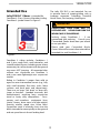
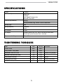
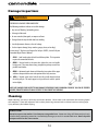
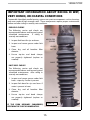
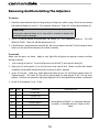
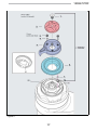
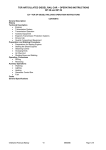
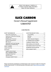
READ THIS MANUAL CAREFULLY!
It contains important safety information.
Keep it for future reference.
LEFTY SPEED FOX RLC 110mm
Owner’s Manual Supplement
120867.PDF
CONTENTS
safety information ...................................
About This Supplement........................... 2
Warning Label.............................................. 3
Intended Use................................................ 3
Bicycle Suspension..................................... 3
Front Brake Requirement......................... 3
Specifications ............................................. 4
tightening torques ................................ 4
fork overview . ........................................... 6
Lefty wheel hub ......................................... 7
Wheel Removal........................................... 8
Wheel Installation....................................... 9
adjustments ..............................................10
Rebound......................................................10
Lockout........................................................11
Low Speed Compression.......................11
Blow Off Threshold...................................12
MAINTENANCE ..............................................13
Schedule......................................................13
Fork Damage..............................................14
Cleaning.......................................................14
Pre-Ride Checks........................................15
Remove/Install Adjusters.......................16
Spring Preload Adjustment..................18
Spring Change...........................................20
Oil Change..................................................22
Air Filter Clean/Re-oil..............................24
Bumper.........................................................24
Grease Renewal.........................................25
Bearing Migration Reset.........................26
xc3 SI stem-steerer..................................28
technical drawings..............................30
suspension glossary............................34
owner notes...............................................35
replacement parts..................................36
Please note that the specifications and information in this manual are subject to change for
product improvement. For the latest product information, go to http://www.cannondale.
com/tech/.
SAFETY
INFORMATION
WARNING
This supplement may include procedures
beyond the scope of general mechanical
aptitude.
About This Supplement
Cannondale Owner’s Manual Supplements
provide important model specific safety,
maintenance, and technical information. They
are not replacements for your Cannondale
Bicycle Owner’s Manual.
Special tools, skills, and knowledge may
be required. Improper mechanical work
increases the risk of an accident. Any
bicycle accident has risk of serious injury,
paralysis or death. To minimize risk
we strongly recommend that owners
always have mechanical work done by an
authorized Cannondale retailer.
This supplement may be one of several for
your bike. Be sure to obtain and read all of
them.
If you need a manual or supplement, or have a
question about your bike, please contact your
Cannondale Dealer immediately, or call us at
one of the telephone numbers listed on the
back cover of this manual.
Warning Label
The warning label shown in Figure 1. is
located on the lower leg of the Lefty. Do
not remove it. If it is missing or damaged,
you can obtain a free replacement from
Cannondale.
You can download Adobe Acrobat PDF
versions of any Cannondale Owner’s Manuals
or Supplements from our website: http://www.
cannondale.com/bikes/tech.
• This manual is not a comprehensive
safety or service manual for your bike.
• This manual does not include assembly
instructions for your bike.
• All Cannondale bikes must be completely
assembled and inspected for proper
operation by a Cannondale Dealer before
delivery to the owner.
Figure 1.
120867.PDF
Intended Use
Lefty FOX RLC 110mm is intended for
Condition 3 (Cross-Country, Marathon) riding.
Condition 3 symbol shown in Figure 2.
The Lefty FOX RLC is not intended for use
in extreme forms of jumping/riding such as
hardcore mountain, Freeriding, Downhill,
North Shore, Dirt Jumping, Hucking etc.
WARNING
UNDERSTAND YOUR FORK AND ITS
INTENDED USE. USING YOUR FORK THE
WRONG WAY IS DANGEROUS.
Industry usage Conditions 1 - 5 are
generalized and evolving. Consult your
Cannondale Dealer about how you intend
to use your bike.
Please read your Cannondale Bicycle
Owner’s Manual for more information about
Intended Use and Conditions 1-5.
Figure 2.
Condition 3 riding includes Conditions 1
and 2, plus rough trails, small obstacles, and
smooth technical areas, including areas where
momentary loss of tire contact with the ground
may occur. NOT jumping. All mountain bikes
without rear suspension are Condition 3,
and so are some lightweight rear suspension
models.
Riding in Condition 3 ranges from mild to
agressive over intermediate terrain (e.g., hilly
with small obstacles like roots, rocks, loose
surfaces and hard pack and depressions).
There are no large “sick drop” or drop offs,
jumps or launches (wooden structures, dirt
embankments) requiring long suspension
travel or heavy duty components. Crosscountry and marathon equipment (tires,
shocks, frames, drive trains) are light-weight,
favoring nimble speed over brute force.
Suspension travel is relatively short since the
bike is intended to move quickly on the ground
and not spend time in the air landing hard.
Bike Suspension
Front Brake Requirement
WARNING
WARNING
YOU COULD HAVE A BAD ACCIDENT IF
YOUR SKILL IS NOT UP TO HANDLING A
SUSPENSION SYSTEM.
DO NOT RIDE WITHOUT A PROPERLY
MOUNTED,
ADJUSTED,
AND
FUNCTIONING FRONT BRAKE SYSTEM.
Suspension systems (front fork, rear shocks)
can increase the handling and stability
of most bicycles. If you lack the skills and
experience necessary to ride at higher
speeds and maneuver over difficult terrain
at the greatly increased performance level,
you can ride faster than your abilities.
You can lose control of the bike in these
conditions and crash. Anytime you lose
control of the bike, especially at high speed
and in advanced terrain, you risk severe
injury or death in a crash.
The Lefty (disc/caliper) acts as an integral
secondary wheel retention system. If the
system is missing or improperly installed,
or if the wheel hub axle bolt should loosen,
the front wheel could slide off the spindle
end.
When mounting IS compatible brake
systems:
Follow brake manufacturer’s instructions
when mounting the brake caliper to the
spindle brake bosses. Do not modify the
fork in any way.
• Ride at reduced speeds.
PLEASE ASK YOUR CANNONDALE
DEALER FOR HELP WHEN INSTALLING
COMPATIBLE FRONT BRAKE SYSTEMS.
• Take time to learn the performance
characteristics of your bike and suspension
components.
•Ride within your skills and abilities.
Make sure the brake disc can not make contact
with the fork boot. A rotating brake disc can
wear through the boot allowing contaminants
into the fork.
•Take a bicycle training course.
CAUTION
USE ONLY 16mm (Cannondale kit #
LEFTYBOLTS/. Longer bolts can result
in contact with the brake rotor causing
severe damage. Check clearance between
the bolt tips and rotor after remounting
the caliper. See Figure 3 item (19).
120867.PDF
specifications
Travel
110mm
External Adjustments
Rebound
Lockout
Low Speed Compression
Blowoff Threshold
Internal Adjustments
Spring
Spring Preload (Sag) 10mm/10 turns Maximum
Spring Type
Coil
Spring Material
Titanium
Steel
Oil Volume
125cc
Oil Weight
Golden Spectro 85/150, Up to 10wt oil can be used if
firmer low speed compression is desired.
Recommended Sag
25% , 27.5mm
tightening torques
Item
Nm
In Lbs
Outer Collar
28.0
248.0
Lefty Steerer Clamp Bolts
9.0
80.0
Rebound Knob Set Screw
1.2
10.6
Loctite®
Loctite 222 (purple)
Blowoff Threshold Set Screw
2.0
18.0
Lefty Wheel Axle Bolt
15.0
133.0
grease
Lefty Brake Disc Bolts
6.2
55.0
Loctite 242 (blue)
Lefty Brake Caliper Bolts
9.0
80.0
FORK OVERVIEW
ITEM
DESCRITION
1.
Rebound Knob
2.
Lockout Lever
3.
Low Speed Compression Knob
4.
Outer Collar
5.
Upper Clamp
6.
Clamp Bolts - 9.0Nm
7.
Outer Tube
8.
Bumper
9.
Lower Clamp
10.
Serial Number
11.
Cable Guide
12.
Zip Tie
13.
Air Filter Assembly
14.
Cable Guide
15.
Boot
16.
Zip Tie
17.
Spindle
18.
Brake Mounts
19.
Brake Bolts - LEFTYBOLTS/
20.
Inner Bearing Seat
21.
Outer Bearing Seat
22.
Spindle Threads
23.
WARNING LABEL
24.
Blowoff Threshold Knob
25.
Lefty Computer Mount (optional)
Figure 3.
120867.PDF
WHEEL HUB
ITEM
1.
DESCRIPTION
Extraction Cap (left hand thread)
2.
Plastic Washer
3.
O-Ring (lubricate)
4.
Axle Bolt
5.
Outer hub bearing
6.
Hub
7.
Inner hub bearing
8.
Hub Seal
9.
Brake Disc
10.
Brake disc bolts
11.
Wheel Truing Tool
Figure 4.
Wheel Removal
1.Place bike in a work stand with
front wheel off the ground. Loosen
the brake caliper mounting bolts.
Tilt the lower caliper bolt out of the
boss so the caliper is up out of the
way of the disc. Snug up on the
upper bolt to hold caliper in place.
Take note of brake alignment shims
between brake bosses and the caliper. Be
sure to reposition correctly.
Figure 5.
2.Turn the hub extraction bolt (1) counterclockwise (ccw) to remove the wheel.
CAUTION
1. Make sure the bolt is completely
disenaged before attempting to
remove the wheel. Never try to
pull the wheel off forcefully.
2. When the wheel is off, to keep
dirt out, cover the hub opening.
3.
Protect spindle from damage
when wheel is removed.
Figure 6.
Continue turning the bolt until the wheel
can be removed easily from the spindle.
Figure 7.
120867.PDF
Wheel Installation
WARNING
1.Inspect inside the wheel hub for
contamination and and the condition
of the hub seal. Take corrective action if
necessary.
Do not contaminate brake caliper, pads,
or rotor with grease.
Wipe the spindle clean with a dry shop
towel and apply a high-quality bike grease
to the spindle bearing lands and end
threads. See next Figure.
CAUTION
LOCATE DISC BETWEEN THE PADS.
Replace shims that are in use, be sure the
shims are positioned between the caliper
(adapter if any) and inner face of the fork
mounts not under the head of the caliper
bolts.
2.Slide the wheel straight onto the spindle
so, the larger hub bearing starts to position
on it spindle seat. At this point, the axle
bolt threads can correctly engage the
threaded spindle if the wheel is held on
straight.
USE ONLY 16mm (Cannondale kit #
LEFTYBOLTS/. Longer bolts can result
in contact with the brake rotor causing
severe damage. Check clearance between
the bolt tips and rotor after remounting
the caliper. See Figure 3 item (19).
NOTE: Install the front wheel by positioning
the bike horizontally with the spindle facing
up. Then place the hub straight down onto
the spindle, and tighten the axle bolt.
3. When the axle bolt threads engage the
spindle, turn the bolt clockwise with finger
force slowly to allow the hub bearings
to slide onto the spindle bearing seats.
Once the hub has been drawn onto the
hub completely, use torque wrench to
tighten to final 15.0 N•m (133.0 In•Lbs).
4. Reinstall the brake caliper. Tighten bolts to
78.0 In•Lbf (9.0 N•m.)
5. Spin the wheel to make sure it spins
freely. Be sure to test the brakes for
proper operation before riding.
adjustments
CAUTION
DO NOT FORCE ADJUSTERS PAST THE
STOPPING POINTS.
Figure 8.
Rebound
The red rebound knob (1) is located on the top of the fork. It has 15 clicks of adjustment. Rebound
controls the speed at which the fork extends after compressing. Turn the knob clockwise (cw) to
close it (slower rebound) and counter-clockwise (ccw) to open it (faster rebound).
CLICKS OUT
(from full in)
SETTING
1
SLOW
15
FAST
To use the knob:
First turn it completely clockwise (cw) until it stops, then turn counterclockwise (ccw) and
count each click. Seven clicks out from closed is a good middle starting point.
10
120867.PDF
Lockout
The blue compression lockout lever (2) allows you to close the compression damping circuit in
the fork. This keeps the fork at the top of its travel, making it harder to compress.
Rotate the lever (2) fully clockwise (cw) until
it stops. The fork will “blow off” in the event that
a big hit is encountered with the fork locked out.
See 4 - Blow off Threshold on next page!
TO LOCKOUT
NOTE: The fork may cycle a couple of times after enabling
lockout. Once complete lockout is achieved, the fork may
continue to move 3 - 5 mm. This is normal and does not
affect performance.
From LOCKED , only rotate the lever (2) counter-clockwise
(ccw) 90°.
TO UNLOCK
While it is possible to the lever counter-clockwise over 360°, it
is only necessary to rotate counter-clockwise 90° to unlock.
Low-Speed Compression
Low-speed compression damping is adjusted with the blue bezel ring (3) below the blue
lockout lever, and has 8 clicks of adjustment. Compression damping controls the speed at
which the fork compresses. Adjust low-speed compression with lockout disabled (lockout lever
fully counterclockwise). As a starting point, turn the low-speed compression dial all the way
counterclockwise (full out) until it stops, then turn clockwise (in) 5 clicks.
CLICKS IN
(from full out)
SETTING
1
SOFT
8
FIRM
11
Figure 9.
Blowoff Threshold
Even when your fork is fully locked out, there are instances when you still want your fork to be
active. To protect your fork’s internal parts, your fork will “blowoff” when it exceeds a certain
threshold force.
You can adjust when the fork blows off—lockout force—by adjusting the blue knob (4) at the
bottom of the fork. Your fork will then respond to hits in the trail (greater lockout force), for
example, but will be locked out (lower lockout force) when you are out of your saddle on a
climb.
In the event of a hit that exceeds this threshold, the fork will blowoff. During this blow-off event,
the damper circuitry may make an audible noise. This is normal.
CLICKS OUT
(from full in)
BLOWOFF
1
At 1 click, the blow off resistance is greatest The fork
requires a harder hit to blowoff the fork compression
lockout. It feels firmest at this setting.
12
In this setting, the blows off resistance is lightest. A
smaller bump will release the lockout. The fork lockout
will feel softest at this setting
12
120867.PDF
maintenance
Schedule
This schedule is intended as a guide only. You must establish a schedule appropriate to your
riding style and conditions.
NORMAL
WHAT TO DO.
RACE
(In Hours)
CHECK FOR DAMAGE. See Damage Inspections on
the next page.
CHECK THE BOOT. Make sure its in good shape and in
place. See page 15.
CHECK TIGHTENING TORQUES.
Torques on page 5.
BEFORE AND AFTER EVERY RIDE
See Tightening
Grease telescope.
50
25
Needle bearing reset*
25
25
Clean air filter
25
10
Damping cartridge oil and seal change*
100
25
AS NEEDED
Inspect, Replace Bumper
PROFESSIONAL SERVICE* ANNUAL (Minimum)
Annually, or when problems are indicated you must have your Lefty fork serviced through
a Cannondale Dealer or an Authorized Headshok Service Center. Your fork should be
disassembled by a suspension professional and evaluated for interal and external part wear
and damaged parts replaced with new ones. It should also include any work described in
any technical bulletins or product recalls.
Our “Factory Tech Room,” (in the USA) provides professional services through Cannondale dealers for
Headshok suspension forks . Please ask your dealer about the service programs available for your model
fork.
WARNING
FREQUENT MAINTENANCE AND INSPECTION IS IMPORTANT TO YOUR SAFETY. YOU
CAN BE SEVERELY INJURED, PARALYZED OR KILLED RIDING ON A BROKEN OR POORLY
MAINTAINED FORK. Ask your Cannondale Dealer to help you develop a complete fork
maintenance program, one that suits where and how you ride.
13
Damage Inspections
WARNING
STOP RIDING A DAMAGED FORK IMMEDIATELY.
The following conditions indicate serious fork damage:
1. Any unusual “klunking” or knocking noises.
2. A change in fork travel.
3. An over-extended, elongated, or compressed boot.
4. Changes from the way the forks had been working
5. Loss of adjustments features, oil or air leakage.
6. Crash or impact damage (deep scratches, gouges, dents, or bending)
For next items 7-10 please read Inspect For Safety in PART II, Section D. of your
Cannondale Bicycle Owner’s Manual.
7. AREA 1 - Small cracks under the bolt head of clamp bolts. This inspection
requires the removal of the bolts.
8. AREA 2 - Vertical cracks in the outer tube (where the races and needle
bearings run). These may show as long, straight lines perhaps several lines
parallel to each other.
9. AREA 3 - Horizontal cracks above and below the intersection of the upper
and lower clamps with the outer tube portion of the Lefty structure.
10. AREA 4 - Vertical cracks at the back of the Lefty spindle directly behind
the safety roll-pin. This may happen in a big event crash and the spindle
twists slightly.
HAVE ANY DAMAGED FORK INSPECTED AND DAMAGE REPAIRED BY YOUR CANNONDALE DEALER. YOU CAN BE SEVERELY
INJURED, PARALYZED OR KILLED IN AN ACCIDENT IF YOU IGNORE THIS WARNING.
Cleaning
When cleaning, use only a mild soap and water solution. Clean water and a common dish washing liquid
will work best. Cover the adjusters with a clean plastic bag secured with a rubber band or masking tape.
Spray off heavy dirt before wiping.
CAUTION
Do not use a pressure washer. Use a low pressure garden hose. Power washing will force contaminants
into the fork promoting corrosion, immediately damage, or result in accelerated wear. Don’t dry with
compressed air for the same reason.
14
120867.PDF
IMPORTANT INFORMATION ABOUT RIDING IN WET,
VERY HUMID, OR COASTAL CONDITIONS
Cannondale Headshok needle bearing system uses precise components such as bearings
and races made of high strength steel. These components require proper maintenance
before and after riding in severely wet conditions.
PRE-RIDE CHECKS
The following service and checks are
recommended above and beyond typical
scheduled maintenance
if riding in
severely wet conditions.
1.Inspect fork boot for rips and tears.
ZIP TIE
AIR FILTER
COVER
2.Inspect and renew grease under fork
boot.
CLAMP
3.Clean, dry, and oil breather filter
element.
ZIP TIE
4.Ensure zip-ties and band clamps
are properly tightened (replace as
needed)
BOOT
POST-RIDE CHECKS
The following service and checks are
recommended above and beyond typical
scheduled maintenance after riding in
severely wet conditions.
1.Inspect and renew grease under fork
boot – wipe dry if water is present.
2.Inspect fork boot for rips and tears if
water is present in boot.
3.Clean, dry, and oil breather filter
element.
4.Ensure zip-ties and band clamps
are properly tightened (replace as
needed).
ZIP TIE
Figure 10.
IF THE FORK BECOMES SUBMERGED,
PERFORM THE CHECKS IMMEDIATELY.
15
Removing And Reinstalling The Adjusters
To remove
1. Hold the rebound knob from turning with your finger tips while using a 2mm hex to remove
the rebound knob set screw (1). Turn counter-clockwise. Then, lift of the rebound knob (2).
CAUTION
Forcing the rebound knob to its stop with a wrench to loosen the
screw will result in damage.
2. Use a 1.5 hex to loosen all three lever set screws (3). Turn counter-clockwise.
REMOVE THEM. Then, lift off the lockout lever (5).
DO NOT
3. Lift off the low speed compression dial (6). Be sure to capture the ball (7) and spring (8) from
hole (a) in the top of the compression valve assembly.
To reinstall
Make sure the parts are clean. Apply a very light film of grease to adjuster contact surfaces
during assembly.
1. Insert spring (8) into (a). Use a bit of grease to stick ball (7) onto top of spring (8).
2.Align pin (b) with groove (c) in (6) and insert into top of fork. Make sure the dial rotates
smoothly and the ball ratchet functions correctly as dial is rotated.
3. Insert (5) into (6). Hold very slight downward pressure on (5) and finger tighten each (3).
Tighten evenly. This locks (5) into (6) by moving balls (4) into groove in (6). Do not overtighten. Set lever resistance by adjusting tightness of (3) until good lever action is achieved.
4.Install (2) and tighten (1) to 1.2 Nm.
No.
Qty
FOX P/N
1.
1
019-01-007
2.
1
210-22-210
3.
3
019-01-006
4.
3
010-01-004-A
5.
1
210-22-228
6.
1
210-22-208
7.
1
039-00-005-A
8.
1
010-01-000-A
CANNONDALE
Cannondale kit KH030/ is a complete adjuster
assembly. It iincludes all parts shown in this
table.
16
120867.PDF
Figure 11.
17
Spring Preload Adjustment (Sag)
Sag is the distance the fork compresses when a rider sits on the bike. The recommended Sag
for the Lefty is 25% of the total travel or 27.5mm. Sag is adjusted by changing the spring preload
with the preload adjustment ring.
1.Start by measuring length (A), the fork length without a rider. Next, Measure (B) fork
length with a rider (B). Calculate A - B = SAG (mm).
2. To set adjust the Sag, remove adjusters. See page 16..
3. Use Shimano tool TL-FC32 to loosen and remove the outer collar. (1). Slightly compress fork
telescope and remove both split rings (2).
4. Use 1.5mm hex to loosen the preload adjuster set screw (3). Turn the preload adjuster (4) to
increase or decrease SAG.
To decrease sag turn the adjuster clockwise (cw)
To increase sag turn the adjuster counter clockwise (ccw).
1 turn is equal to 1mm of sag change
CAUTION
The preload adjust ring (4) must be set at a minimum of two full turns after
it contacts the top of the spring. THE MAXIMUM NUMBER OF TURN AFTER
MINIMUM PRELOAD IS SET IS 10. If the desired sag for your body weight can
not be achieved using the preload ajuster, consider changing to a softer or
firmer spring (4). See next page.
5.Tighten the 1.5mm preload adjust set screw finger tight.
5.Apply grease to the split ring groove (a) and reinstall the split rings (2) with the “TOP” marking
up. Raise the telescope and reinstall the outer collar (1). Tighten with Shimano tool TL-FC32
to 28Nm. Reinstall the adjusters. See previous page.
18
120867.PDF
Figure 12.
19
Spring Change
The following procedure should only be
completed by a professional bike mechanic.
1.Remove the adjusters. See page 16.
2. Use Shimano tool TL-FC32 to loosen and
remove the outer collar. See page 18.
3. Lower the telescope and remove the two
splits rings (1) from the compression
assembly groove (a).
4.Hold spring shaft flats with 16mm wrench.
Locate a 21mm wrench on the flats and
turn it the compression valve assembly
counter-clockwise to remove it.
Figure 13.
5.Compress the preload tube (2) and remove
the spring clip (3) from the groove (b).
6. Lift out the spring shaft assembly from
inside the spring: preload tube (2),
preload adjust ring (4), O-Ring (5), Spacer
(6), O-ring (7).
7. Lift out the spring (8). The following
Cannondale spring kits are available for
the 110mm Lefty FOX RLC. Note: Titanium
springs are a lighter wieght spring.
Figure 14.
Titanium Spring Kits
KH007/
SOFT
KH008/
STANDARD
KH009/
FIRM
KH010/
X-FIRM,
Steel Spring Kits
KH017/
KH018/
KH019/
KH020/
KH021/
SOFT,
STANDARD,
FIRM
X-FIRM
XX-FIRM
Figure 15.
20
120867.PDF
8.Coat the new spring with Maxima Red
Spring Grease.
9.Install the spring with the small isolator (c)
up. The large isolator (d) goes down.
10. Apply Loctite 242 (blue) to the compression
valve assembly (9) (e) threads and install
it onto the top of the preload tube (2).
Be sure to align the key (f ) with the slot
(g) on the top of the rebound damper.
Make sure the compression clamp (10)
orientation
is
as
Figure 16.
shown.
Hold the spring shaft on the flats with a
16mm wrench. Use a 21mm wrench to
tighten the compression valve assembly
to 7.9Nm. Turn clockwise.
11.Apply grease to the split ring groove (a)
and reinstall the split rings (1) with the
“TOP” marking up.
12.Raise the telescope and reinstall the outer
collar. Tighten with Shimano tool TL-FC32
to 28Nm.
13.Reinstall adjusters.
Figure 17.
Figure 18.
21
Oil Change
The following procedure should only be
completed by a professional bike mechanic.
1.Remove the adjusters. See page 16.
2. Use a 26mm socket to remove the
compression valve assembly.
Figure 19.
3. Lift out the compression valve assembly.
Note the pin (a).
4. Invert the fork over an oil collection pan.
Cycle the fork several times to pump out
the oil.
5.At the bottom of the fork, with a 24mm
socket, turn the damper counter-clockwise
and lower it out of the spindle enough
to drain out oil. Then return reinstall the
damper and tighten to 28.0Nm.
a
Figure 20.
Figure 21.
22
120867.PDF
5.Pour a small amount of the specified
oil into the top of the fork up
to the valve assembly threads.
Golden Spectro 85/150
Figure 22.
Slowly cycle the fork. You will see air bubbles
arise through the oil as the oil flows into
the damper.
The damper requires 125cc of the oil.
Continue filling and cycling until all the
oil has been poured and no bubbles are
present.
Figure 23.
6.Apply grease to the compression valve
assembly threads and the O-ring.
Carefully reinstall the assembly into the
top of the fork by hand. Allow the pin to
drop into the slot in the top of the damper
and turn the assembly by hand a few turns
before using the socket to tighten.
Tighten to 6.0Nm
7.Reinstall the adjusters.
Figure 24.
23
Air Filter Clean/Re-Oil
The air filter assembly is located over two air
holes in the outer tube. The air filter assembly
stops the passage of dirt and water which
would damage the internal fork components.
The small holes (a) at the base of the filter cover
(2) should remain clear and be positioned to
the sides of the and not to the front or back
of the bicycle to minimize the chance dirt
thrown by the wheels will plug the holes.
The foam filter element (1) should be cleaned
and re-oiled frequently. This can be performed
without removing the filter from the fork.
Figure 25.
Slide cover up off the foam. In place, massage
the foam air filter element with warm soapy
water preventing water or soap from entering
the holes in the outer tube.
Allow to dry completely, and reapply a highquality foam air filter oil before reinstallation.
Be sure to massage the oil into the foam.
A foam element without the oil is ineffective.
HD209/BLK
Lefty Air Filter Assy
Frame Bumper
The bumper (1) located on the outer tube (2)
between the clamps. It cushions the frame
from contact with the fork. Replace it with a
new one if it ever becomes damaged, torn,
or missing. To remove it, remove the band
(3) from the bumper groove and unwrap the
bumper.
HD215/
Lefty Bumper
Figure 26.
24
120867.PDF
Periodic Grease Service
Under the Boot
1.Remove the front wheel.
2.Carefully release the upper and lower zip
ties securing the fork boot. If the boot is
secured with a band clamp, loosen and
remove the clamp (s).
3. Lift the unsecured boot up to expose the
inner tube .
Figure 27.
4. Wipe off the old grease with a dry shop
towel.
5.Re-apply a fresh heavy coating of grease.
Any clean high-quality bicycle bearing
grease selected for riding temperatures and
environment can be used. We assemble
forks at our factory using Royal Purple Ultra
Performance Grease NLGI #2 (ISO 46 BASE).
Cycle the fork several times between
applying grease to the new grease is
worked into the bearings.
6. Reposition the boot and replace the zip
ties. Make sure the zip ties are very tight.
Loose zip ties may allow water or dirt to
pass behind the boot.
WARNING
CHECK THE BOOT BEFORE EACH RIDE.
DON’T RIDE IF IT IS DAMAGED.
REPLACE IT WHEN YOU FIND DAMAGE.
Figure 28.
25
Bearing Migration Reset
Inside the fork the four needle bearing
cages (1) move independently up and down
between each inner (2) and outer race pair
(3). This bearing arrangement provides
numerous advantages to fork performance
but requires simple periodic maintenance to
ensure proper alignment.
Bearing Migration
If a cage or cages shifts out of alignment up
or down in relation to the others it is said to
have “migrated.” This migrated condition will
limit travel.
Figure 29.
Needle bearing migration is normal and
expected. However, if the fork is ridden in
this state for extended periods, the fork can
be damaged.
Evidence of migration is:
1An unusual "top out" noise .If an unusual
noise is heard, the extended fork length
should be measured to confirm the
condition.
2. The
extended
fork’s
length
is
maximum
reduced.
If
migration
re-occurs
frequently
(immediately after resetting), the cause
could be damage present in the inner
or outer races, ,bearings/cages or other
fork parts. Inspection and replacement
of damage parts will be required to
correct a persistent problem with bearing
migration.
ALIGNED
Figure 30.
26
MIGRATED
120867.PDF
To reset
The following procedure should only be
completed by a professional bike mechanic.
1. Place the bike in a work stand.
2.Remove the adjusters.
3. Remove the outer collar the Shimano
bottom bracket tool TL-FC32.
4.Compress the telescope and remove the
two split rings from the top cap..
5.Fully extend the fork, and measure from
top edge of outer tube to bottom edge of
spindle. See right. If the length is out of
specification do the following:
Firmly extend the telescope until it stops
(tip - listen for the knocking at full extension
to change from a hollow sound to a solid
sound - this indicates full extension has
been achieved). Do this several times
using only moderate force, extend the
lower fork leg using a pumping action.
After, you have performed this action
several times, re-measure.
CAUTION
If fork is out range following
reset attempt, it may be
damaged internally. The fork
should be disassembled and
inspected by a professional
mechanic before it is ridden.
Figure 31.
27
XC3 SI Stem-Steerer
The following procedure should be completed
by a professional bike mechanic.
Installation
1. Loosen both clamp bolts (1).
3.Position the Lefty clamps onto the
headtube assembly as shown.
4.Insert Cannondale tool KT020/ through
the bottom clamp, into the head tube,
and out the upper clamp.
5. Make sure the plastic ring (6) is on the
stem. Insert the bottom of the stemsteerer onto the top of the tool.
6. Remove the cap (1) from the top of the
steerer. Use a rubber mallet to drive the
stem-steerer into the head tube until it
stops. Return the cap (1).
7.Clean and apply grease to the steerer bolt
threads and install into the bottom of the
stem-steerer. Align handlebar and tighten
the bolt to 9 N•m.
Figure 32
8..Tighten the upper and lower clamp bolts
to 9 N•m.
Removal
1 Loosen upper and lower clamp bolts.
2.Remove steerer bolt (10).
3.Insert the small end of KT020/ into the
bottom of the stem-steerer and drive the
stem-steerer up out of the head tube.
Figure 33.
28
120867.PDF
An alloy frame headset with
bearing cups is shown here. If the
frame headtube is carbon fiber, the
bearing cups are bonded in place
and non-removable.
WARNING
NOTES:
The steerer bolt (10) is a
structural part and must be
installed.
ITEM
DESCRITION
1.
Cap
2.
O-Ring
3.
Stem
4.
Handlebar Clamp
5.
Clamp Bolt
6.
Plastic Ring
7.
Bearing Seal
8.
Bearing
9.
Bearing Cup
10.
Stem-Steerer Bolt
1. When removing or installing
steerer bolt (10), insert 5mm
Allen key completely to prevent
stripping the bolt.
2.The drain hole (a) in (10) enables
accumulated moisture inside
the headtube to drain out. Use a
toothpick to keep it clear..
Figure 34.
29
Figure 35.
30
120867.PDF
Figure 36.
31
ITEM
DESCRIPTION
DAMPER BODY ASSY
1.
DAMPER BODY 110mm
2.
COUPLER
3.
4.
5.
6.
7.
8.
9.
10.
11.
12.
O-RING 17.00 ID x 1.00 W
O-RING 20.00 ID x 1.00 W
O-RING 2-020 21.95 ID x 1.78 W
O-RING 8.00 ID x 1.00 W
O-RING 3.00 ID x 1.00 W
CRUSH WASHER, PLASTIC
NUT
BLOWOFF KNOB
SET SCREW
BASE CAP
REBOUND SHAFT ASSY
13.
14.
15.
16.
17.
18.
19.
20.
21.
22.
23.
24..
SHAFT COUPLER
RING
REBOUND SHAFT
ADJUST ROD LOWER
SEAL HEAD
O-RING 10.00 ID x 1.50 W
O-RING 12.50 ID x 2.00 W
O-RING 14.50 ID x 1.00 W
TOPOUT PERCH UPPER
NEGATIVE SPRING
TOPOUT SPRING PERCH
PISTON ASSY
LENGTH (mm)
TRAVEL (mm)
130
110
A
137.3
117.3
B
664.3
644.3
C
422.4
422.4
NOTE: Apply NGLI-2 synthetic grease to all O-Rings
Figure 37.
32
120867.PDF
Figure 38.
33
the fork gets fully compressed.
suspension
glossary
Damping - The process of dissipating energy
and slowing down the suspension motion.
Damping absorbs the force of a bump or
landing. Damping is usually done with oil, but
can be done with air and friction as well.
Spring - The part of a suspension fork or shock
that holds the rider/bike up. Springs can be
metal coils (steel or titanium) or high pressure
air.
Compression - The process of squeezing
together. The front and rear suspension
compress when hitting a bump, landing off a
jump, or braking for corners. Compression can
refer to the spring or damping (compression
damping).
Rebound - The process of extending back
from a compressed state. The front and rear
suspension rebound after being compressed
from a bump or jump landing. Rebound
can refer to the spring or damping (rebound
damping).
Low Speed (compression or rebound) Low speed damping references the speed
at which the fork/damper travels through its
stroke. It does NOT refer to the speed at which
the rider is moving. Low speed bumps are
typically round in shape or smooth actions
like jump landings and pedal bob. In the case
of rebound, it mostly refers to rebound speed
caused by smaller bumps where the fork does
not get fully compressed.
High Speed (compression or rebound) High speed damping references the speed
at which the fork/damper travels through
its stroke. It does NOT refer to the speed at
which the rider is moving. High speed bumps
are typically square in shape or harsh terrain
like sharp-edged rocks that may cause pinch
flats. In the case of rebound, it mostly refers to
rebound speed caused by larger bumps where
34
Bottom Out - When the front or rear
suspension fully compresses to absorb a bump
or jump landing. A hard stop is usually felt at
bottom out.
Top Out - When the front or rear suspension
fully extends after absorbing a bump or jump
landing. A soft stop is usually felt at top out.
The fork and shock are typically topped out
without a rider on the bike.
Compression Adjuster - Used to adjust the
front or rear compression damping setting.
Rebound Adjuster - Used to adjust the front
and rear rebound setting
Sag - Refers to how much the front and rear
suspension compress when a rider sits on
the bike. Sag is measured as a percentage
of suspension travel. Typical sag values are:
20-30% for XC riding and 25-35% for Trail/
Freeride.
Preload
- Refers to how much initial
compression is applied to a spring. In the
case of an air spring, preload is achieved by
increasing the air pressure. You use preload
to adjust the sag. More preload decreases the
sag. Less preload increases the sag.
Spring Rate - Refers to the strength of a
spring. A spring with a higher rate is stiffer, a
lower rate softer.
Diving - Normal
movement
when a
suspension fork compresses resulting in a
downward change in the the angle of the
bicycle. Mostly occurs when braking.
Revalve - Revalving is the process of changing
the internal compression and rebound shims
to change the flow of oil through passages in
the forks and shock. A suspension specialist
should revalve your bike’s suspension.
120867.PDF
owner notes
Record maintenance history, service, or set up information .
DATE
WORK PERFORMED
35
replacement parts kits
KIT #
KH007/
KH008/
KH009/
KH010/
KH017/
KH018/
KH019/
KH020/
KH021/
KH025/
KH011/
DESCRIPTION
SPRING, SOFT, TI
SPRING, STANDARD, TI
SPRING, FIRM, TI
SPRING, X-FIRM, TI
SPRING, SOFT, FE
SPRING, STANDARD, FE
SPRING, FIRM, FE
SPRING, X-FIRM, FE
SPRING, XX-FIRM, FE
FOX RLC Preload Tube
FOX RLC Upgrade Kit
KIT #
KH016/
HD215/
QC678/
HD209/BLK
HD208/
HD161/
HD175/BLK
HD185/BLK
HD011/
LEFTYBOLTS
KF364/
KH012/
FOX RLC Seal Kit
QSMSEAL/
KH013/
FOX RLC 110 Rebound Damper
QHDST/EBO
KH028/
KH015/
FOX RLC Rebound Shaft
FOX RLC Compression Damper
HD169/
KT020/
KH029/
FOX RLC Seal Head
HDR2L/020
KH026/
FOX RLC Compression Clamp
HDR2L/021
KH027/
FOX RLC Retaining Ring
HDR2L/022
HD226/
Golden Spectro 1 US QT.
HDR2L/023
KF205/
Split Rings 2
HDR2L/024
HDR2L/025
HDR2N/024
DESCRIPTION
FOX RLC Outer Collar
Lefty Bumper
Lefty Boot 110mm
Lefty Air Filter Assy
Lefty Outer Race Clip 5
Lefty Needle Bearings
Zip Ties 50 Black
Zip Ties Double Head 10 Black
Band Clamps 2
16mm Brake Bolts 2
Lefty Computer Mount
Headshok Headset Bearing Seal
(Alloy)
Headshok Headset Cup 2, plus 1
Bearing
Headshok Headset Bearings 2
Steerer Tool “The Ernie”
Kit, Race-Inner: 10.197”259.0mmx.020-.51mm (4)
Kit, Race-Inner: 10.197”259.0mmx.021”-.53mm (4)
Kit, Race-Inner: 10.197”259.0mmx.022”-.56mm (4)
Kit, Race-Inner: 10.197”259.0mmx.023”-.58mm (4)
Kit, Race-Inner: 10.197”259.0mmx.024”-.61mm (4)
Kit, Race-Inner: 10.197”259.0mmx.025”-.635mm (4)
Kit,Race-Outer:8.110”-206mmx.024
For an up to date list of kits available for your bike, please visit our
Tech Center at : http://www.cannondale.com/tech/
36