1
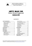
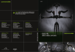
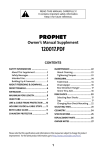
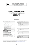
129975
WARNING! READ THIS SUPPLEMENT AND YOUR CANNONDALE BICYCLE
OWNER’S MANUAL. BOTH CONTAIN IMPORTANT SAFETY INFORMATION.
KEEP BOTH FOR FUTURE REFERENCE.
CANNONDALE EUROPE
CANNONDALE UK
Cycling Sports Group, Inc.
172 Friendship Road,
Bedford, Pennsylvania, 15522-6600, USA
(Voice): 1-800-BIKE-USA
(Fax): 814-623-6173
[email protected]
Cycling Sports Group Europe, B.V.
mail: Postbus 5100
visits: Hanzepoort 27
7570 GC, Oldenzaal, Netherlands
(Voice): +41 61.4879380
(Fax): 31-5415-14240
[email protected]
Cycling Sports Group
Vantage Way, The Fulcrum,
Poole, Dorset, BH12 4NU
(Voice): +44 (0)1202 732288
(Fax): +44 (0)1202 723366
[email protected]
CANNONDALE AUSTRALIA
CANNONDALE JAPAN
WWW.CANNONDALE.COM
Cycling Sports Group
Unit 8, 31-41 Bridge Road
Stanmore NSW 2048
Phone: +61 (0)2 8595 4444
Fax: +61 (0) 8595 4499
[email protected]
Namba Sumiso Building 9F,
4-19, Minami Horie 1-chome,
Nishi-ku, Osaka 550-0015, Japan
(Voice): 06-6110-9390
(Fax): 06-6110-9361
[email protected]
© 2013 Cycling Sports Group
129975 (01/13)
OWNER’S MANUAL SUPPLEMENT
SUPERMAX
CANNONDALE USA
SUPERMAX.
OWNER’S MANUAL SUPPLEMENT.
In this supplement, particularly important information is presented in the following ways:
WARNING
NOTICE
TIP
Indicates a hazardous situation which, if not
avoided, could result in death or serious injury.
Indicates special precautions that must be
taken to avoid damage.
A TIP provides helpful information.
This manual meets EN standards
14764, 14766, and 14781.
Vélo certifié conforme aux exigences du décret
N 95-937 du 24 août 1995 norme NFR030
129975.PDF
About This Supplement
Cannondale Owner’s Manual Supplements provide
important model specific safety, maintenance, and
technical information. They are not replacements
for your Cannondale Bicycle Owner’s Manual.
This supplement may be one of several for your
bike. Be sure to obtain and read all of them.
If you need a manual or supplement, or have a
question about your bike, please contact your
Cannondale Dealer immediately, or call us at one
of the telephone numbers listed on the back cover
of this manual.
You can download Adobe Acrobat PDF versions of
any Cannondale Owner’s Manuals or Supplements
from our website: www.cannondale.com/bikes/tech.
• This manual is not a comprehensive safety or
service manual for your bike.
• This manual does not include assembly
instructions for your bike.
• All Cannondale bikes must be completely
assembled and inspected for proper operation
by a Cannondale Dealer before delivery to the
owner.
Table of Contents
Safety Information.............................. 2
Intended Use...................................... 2
Damage / Inspection........................... 2
Disassembly / Modification.................. 3
Tire-to-Crown Clearance...................... 3
TECHNICAL INFORMATION......................... 4
SUPERMAX Structure......................... 4
Wheel Hub......................................... 5
Setting Sag...................................... 6-7
Pbr Lockout...................................... 8
Pbr Rebound.................................... 8
Wheel Removal................................... 9
Wheel Installation............................. 10
MAINTENANCE....................................... 11
Schedule.......................................... 11
Cleaning........................................... 12
Tightening Torques........................... 12
Frame Bumper................................. 13
Moto Guard...................................... 13
Manual Reset................................... 14
Cannondale Limited Warranty.......... 15
WARNING
REPLACEMENT PARTS............................ 16
This supplement may include procedures
beyond the scope of general mechanical
aptitude.
Special tools, skills, and knowledge may be
required. Improper mechanical work increases
the risk of an accident. Any bicycle accident
has risk of serious injury, paralysis or death.
To minimize risk we strongly recommend that
owners always have mechanical work done by
an authorized Cannondale retailer.
1
01/13
SAFETY INFORMATION
Damage / Inspection
Intended Use
SUPERMAX
TRAVEL
130 mm
WARNING
INTENDED USE
RIDING WITH DAMAGE IS DANGEROUS.
STOP RIDING IMMEDITE IF DAMAGE IS
PRESENT.
All Mountain,
Overmountain,
The following conditions indicate that serious
fork damage is present:
ASTM CONDITION 4
• Any unusual “klunking” or knocking
noises.
SUPERMAX ARE NOT INTENDED - For use
in extreme forms of jumping/riding such as
hardcore mountain, Freeriding, Downhill,
North Shore, Dirt Jumping, Hucking etc.
• Change in travel.
• Changes in normal functions.
• Loss of adjustments features, oil leaks, or
air leaks.
• Crash or impact damage (deep scratches,
gouges, dents, or bending)
WARNING
• Any small cracks under the bolt head
of upper and lower clamp bolts. This
inspection requires the removal of the
bolts.
UNDERSTAND YOUR LEFTY AND ITS INTENDED
USE. USING YOUR LEFTY THE WRONG WAY IS
DANGEROUS.
• Horizontal cracks above and below the
intersection of the upper and lower clamps
with the outer tube portion of the Lefty
structure.
Industry usage Conditions 1 - 5 are generalized
and evolving. Consult your Cannondale Dealer
about how you intend to use your bike/fork.
Please read your Cannondale Bicycle Owner’s
Manual for more information about Intended
Use and Conditions 1-5.
• Vertical cracks in the outer tube (where the
races and needle bearings run). These may
show as long, straight lines perhaps several
lines parallel to each other.
YOU CAN BE SEVERELY INJURED, PARALYZED
OR KILLED IN AN ACCIDENT IF YOU IGNORE
THIS WARNING.
Please read Inspect For Safety in PART II,
Section D. of your Cannondale Bicycle Owner’s
Manual.
If your SUPERMAX is damaged, do not ride
it. Contact your Cannondale Dealer to arrange
service through an authorized service center.
YOU CAN BE SEVERELY INJURED, PARALYZED
OR KILLED IN AN ACCIDENT IF YOU IGNORE
THIS WARNING.
2
129975.PDF
Disassembly or Modification
Tire-to-Crown Clearance
WARNING
WARNING
DO NOT DISASSEMBLE OR MODIFY YOUR
LEFTY IN ANY WAY.
Modification or installation of damping
cartridge/spacers other than specified; or
installing over-sized tires can result in incorrect
tire-to-crown clearance
Improper service or modification can
lead to serious fork damage or serious
personal injury.
• Do not disaassemble the fork.
• Do not attempt modification in any
way.
• Do not drill, file, cut or remove
material from any part.
2
10mm
• Do not attempt to repair damage.
• Do not weld, clamp, or bond anything
to the fork.
• Do not attempt to remove the damping
cartridge or other internal fork parts.
1
If tire clearance is less than minimum
specified, the rotating tire could come into
contact with the frame causing the wheel to
stop suddenly. This can throw a rider off the
bicycle or result in a loss of control and crash.
The MAINTENANCE section of this
supplement includes information about
regular owner maintenance practices
that can keep your fork in good operating
condition.
CHECK FOR MINIMUM TIRE FORK/FRAME
CLEARANCE (10 mm) WITH ALL AIR RELEASED
FROM LEFTY AND FULLY COMPRESSED.
All other service and maintenance
procedures must be completed through
an Authorized Headshok Service Center.
Contact your Authorized Cannondale
Dealer for more information.
Measure between the top of the properly
inflated tire (1) and the bottom of the fork
steerer (2).
YOU CAN BE SEVERELY INJURED, PARALYZED
OR KILLED IN AN ACCIDENT IF YOU IGNORE
THIS WARNING.
YOU CAN BE SEVERELY INJURED,
PARALYZED OR KILLED IN AN ACCIDENT IF
YOU IGNORE THIS WARNING.
3
TECHNICAL INFORMATION
1.
Supermax Structure
3.
5.
Identification
1.
2.
3.
4.
5.
6.
7.
8.
9.
10.
11.
12.
13.
14.
15.
16.
17.
18.
19.
20.
21.
22.
23.
24.
25.
26.
27.
28.
PBR Lockout Button
PBR Rebound Dial
XLR Rebound Dial
A
B
24.
XLR/PBR Carbon Outer Collar
Bonded Upper Clamp
Clamp Bolt
Serial Number Location
11.
Frame Bumper
Carbon Outer Tube (carbon fiber)
8.
Brake Housing Guide
25.
Bonded Lower Clamp
Guard
Guard Brake Housing Clamp
Lower Collar Assy.
Sag O-Ring
OPI Inner Tube
Guard Mounting Screws
Hub Spindle
Inner Bearing Land
Outer Bearing Land
Axle Bolt Threads
Schrader Valve
23.
Brake Adapter
180mm
180mm
SUPERMAX
System Integration Headtube
HYBRID
Steerer (1.5 Stems Only)
Damping Cartridge (shown removed)
SOLO Air Assembly
Volume Reducer(s)
6.
Loctite 242 (blue)
7-9 Nm (62-80 InLbs)
7.
10.
26.
9.
A
B
C
14.
12. 27.
15.
13.
16.
Loctite 242 (blue)
9 Nm (80 InLbs)
Frame
Size
SI Headtube
Length - (A)
Clamp
Spacing - (B)
Steerer
Kit - (25)
Damping
Cartridge
Thread Position
SMALL
97mm
100.2mm
KH118/097HT
A
MEDIUM
109.7mm
112.9mm
KH118/109HT
A
LARGE
122.4mm
125.6mm
KH118/122HT
B
X-LARGE
134.4mm
137.6mm
KH118/134HT
B
4
21.
20.
28.
18.
17.
19.
22.
129975.PDF
Wheel Hub
■ Either a SUPERMAX or LEFTY HYBRID wheel hub may be used with the SUPERMAX. The wheel hub
must be matched with its correct brake adapter. See item 23 on previous page.
■ The hub cap is a left-hand thread. It retains the axle bolt assembly within the and should only be
removed when replacing the bearings or axle bolts parts, not when removing the wheel.
■ The axle bolt is a right hand (normal) thread. Insert a 5 mm allen key. Turn it clockwise to install a
wheel. Turn it counter-clockwise to remove a wheel.
QC118/
KB61805/
KH105/24H
KH105/28H
KH105/32H
KIT,HUB, LEFTY 24H6-BOLT/BLK
KIT,HUB, LEFTY 28H6-BOLT/BLK
KIT,HUB, LEFTY 32H6-BOLT/BLK
(Items 1,2,3, and 4)
KH119/32
KIT,HUB, SUPERMAX 32H6-BOLT/BLK
(Items 10, 1,2,3, and 4)
KB61902/
10.* 1.
Light
grease
2.
7.
3.
Identification
1.
2.
3.
4.
5.
6.
7.
8.
9.
10.
A
4.
Hub Bearing Seal
Inner Hub Bearing
LEFTY Hub Shell
Outer Hub Bearing
Axle Bolt Assy.
Lefty Hub Wheel Building Tool
Axle Bolt
Hub Cap (Left-hand thread!)
Shimano Tool TL-FW30
Ring Clip (*SUPERMAX Hub Only)
37 mm
C
Loctite 242
(blue)
CENTERLINE OF WHEEL
9.
Shimano TL-FW30
6.
DIMENSIONS FOR WHEEL BUILDING
D
B
5 mm
15 Nm (133 InLbs)
5.
QC117/
QCTL108/
LEFTY
HYBRID
SUPERMAX
A
Disc Flange Diameter
68.0 mm
B
Non Disc Flange Diameter
54.0 mm
C
Disc Flange To Center
25.8mm
18.8 mm
D
Non Disc Flange To Center
34.6mm
31.6 mm
5
Setting Sag
Sag is the distance the SUPERMAX compresses when the bike is statically loaded with your
body weight in your riding position. Set it according to the SUPERMAX travel. Sag is set by
changing the air pressure through the Schrader valve at the bottom of the SUPERMAX
Set Recommended Initial Air Pressure
(Set before measuring sag)
RIDER WT.
(Lbs/Kg)
120 / 55
130 / 60
140 / 65
155 / 70
165 / 75
175 / 80
185 / 85
200 / 90
210 / 95
220 / 100
230 / 105
29ER
PSI
Bar
64
4.4
66
4.6
70
4.8
74
5.1
78
5.4
80
5.5
83
5.7
87
6.0
90
6.2
93
6.4
95
6.6
Be aware that conventional pump gages have variations. Therefore, we recommend you to
fine tune your set up with the Recommended Sag.
Fine Tune to 25% Recommended Sag
(Adjust the air pressure +/- to set this sag)
SUPERMAX TRAVEL (mm)
130
120
100
90
25% SAG (mm)
32
30
25
22
20% SAG - Minimum
26
24
20
18
30% SAG - Maximum
39
36
30
27
SUPERMAX AIR PRESSURE LIMITS
Minimum: 50 psi, 3.4 bar
Maximum: 225 psi, 15.5 bar
6
129975.PDF
To set sag:
1. Remove the Schrader valve cap (1) at the
bottom of the SUPERMAX Attach a bicycle
suspension pump to the Schrader valve
(2). See Figure 1.
2.
2. Set the recommended intial starting air
pressure according to your weight.
1.
1
3. Slide the sag O-ring (3) against the wiper
seal (4). See Figure 2.
3. Sit on bike in riding position and
dismount.
4.
3.
Note: Your riding position affects weight
distribution and therefore sag. For
example, in the “Attack” position
(Figure 3). the rider’s weight is distributed
equally front and rear.
2
4. Measure the sag distance. See Figure 4.
Sag Trouble Shooting
Too much sag
add air in small
increments
Too little sag
reduce air in small
increments
Excessive
bottom out
increasing air pressure
harsh ride or
limited travel
reduce air pressure
50/50
Attack
3
NOTICE
A dirty pump or valve end can result in
contamination, damage, and air loss.
Make sure pump and valve are clean
before attachment.
SAG
4
7
PBR Lockout
1.
2.
OPEN POSITION
LOCKED POSITION
In the open position, LEFTY travel is active.
The red rebound dial (1) is in the down
position. To go to the locked position, press
the blue button (2).
In the locked position, LEFTY travel is
locked. The red rebound dial is up. To go
back to the open position, press the red
redound dial down until it clicks.
PBR Rebound Dial
Rotate dial in the “–” direction (counter-clockwise) to increase rebound speed (faster).
Rotate dial in the “+” direction (clockwise) to decrease rebound speed (slower).
8
129975.PDF
Wheel Removal
1. If needed, loosen the brake line clamp on
the front of the moto guard so the line can
move freely. This will make handling the
brake caliper and attached adapter easier.
2. See Figure 1. Use a 5 mm Allen key to
loosen and back out both brake adapter
mounting bolts enough so that the adapter
and attached caliper can slide up and be
removed from the spindle together. It is
not necessary to completely remove the
adapter bolts.
Carefully move the brake caliper out of the
way and protect it from damage.
2. See Figure 3. Insert a 5 mm Allen key
into the axle hub bolt and turn it counterclockwise.
Continue turning the extraction bolt
until the wheel is disenaged and can be
removed easily from the spindle end.
See Figure 4.
NOTICE
■ Make sure the axle bolt is completely
disengaged before attempting to
remove the wheel. Never try to pull
the wheel off forcefully.
■ When the wheel is off, to keep dirt
out, cover the hub opening.
■ Protect spindle from damage when
wheel is removed.
9
Wheel Installation
1. Wipe the spindle clean with a dry shop towel.
Apply a high-quality bike grease to I.D. of the
bearings inside the hub.
WARNING
DO NOT CONTAMINATE BRAKE CALIPER,
PADS, OR ROTOR WITH GREASE.
2. Slide the wheel straight onto the spindle. Turn the axle bolt clockwise to engage the
spindle threads. Make sure the wheel and
spindle are supported while tightening the hub
bolt.
3. Once the hub has been drawn onto the hub
completely, use torque wrench to tighten to final
15.0 Nm (133.0 InLbs). See Figure 1.
4. Reinstall the brake adapter onto the spindle
bosses making sure that the brake disc locates
properly between the pads.
NOTICE
■ LOCATE BRAKE ROTOR BETWEEN THE PADS.
Apply Loctite 242 (blue to the threads and
tighten the adapter mounting bolts to 9 Nm,
(78 IN Lbs). See Figure 2.
WARNING
5. Spin the wheel to make sure it moves freely.
Be sure to test the brakes for proper operation
before riding.
DO NOT RIDE WITHOUT A PROPERLY MOUNTED,
ADJUSTED, AND FUNCTIONING FRONT BRAKE SYSTEM.
The (disc/caliper) acts as an integral secondary
wheel retention system. If the system is missing
or improperly installed, or if the wheel hub axle
bolt should loosen, the front wheel could slide
off the spindle end.
Follow brake manufacturer’s instructions when
mounting the brake caliper to the spindle brake
bosses. Do not modify the fork in any way.
PLEASE ASK YOUR CANNONDALE DEALER FOR HELP
WHEN INSTALLING COMPATIBLE FRONT BRAKE SYSTEMS.
10
129975.PDF
MAINTENANCE
Schedule
This schedule is intended as a guide only. You must establish a schedule appropriate to your
riding style and conditions.
SERVICE ITEM
FREQUENCY (NORMAL
RIDING)
WHO?
Check for damage
Pre/Post ride
Bike owner
Check for Tightening Torques
First Ride / Every 4-5 rides
Bike owner
Replace Frame Bumper, Guard
As Needed
Bike owner
Manual Reset
50 hours
Bike owner
Telescope Lubrification
100 hours
Dealer
Damper Service:
Air spring/Damping Cartridge Inspection
100 hour or every year
Dealer
Full Service (Telescope Rebuild + Damper
service)
200 hours
Headshok Service Center
RACING - If you race with your SUPERMAX, you will have to perform the items listed twice as often. (i.e. 50hrs becomes
25hrs)
SCHEDULE PROFESSIONAL FORK SERVICE ANNUALLY (Minimum)
Annually, or when problems are indicated you must have your SUPERMAX serviced through a Cannondale
Dealer or an Authorized Headshok Service Center. Disassembly and inspection by a suspension
professional is required to evaluate the internal and external parts, identify wear or damage. Damaged
parts must be replaced with new ones and the work must also include any work described in any technical
bulletins or product recalls.
WARNING
FREQUENT MAINTENANCE AND INSPECTION IS IMPORTANT TO YOUR SAFETY. YOU CAN BE
SEVERELY INJURED, PARALYZED OR KILLED RIDING ON A BROKEN OR POORLY MAINTAINED
FORK. Ask your Cannondale Dealer to help you develop a complete maintenance program,
one that suits where and how you ride.
11
Cleaning
Clean using only a mild soap and water solution. Clean water and common liquid dish
washing soap will work best. Be sure to cover the adjusters with a clean plastic bag secured
with a rubber band or masking tape. Spray off heavy dirt before wiping. Spray indirectly.
NOTICE
• DO NOT USE A PRESSURE WASHER. Use a low pressure garden hose. Power washing
will force contaminants into the fork promoting corrosion, immediately damaging, or
result in accelerated wear.
• DON’T DRY WITH COMPRESSED AIR FOR THE SAME REASON.
Tightening Torques
Correct tightening torque for the fasteners (bolts, screws, nuts) on your bicycle is very
important to your safety.the durability and performance of your bicycle. We urge you to have
your Dealer correctly torque all fasteners using a torque wrench. If you decide to tighten
fasteners yourself always use a good torque wrench!
Description
Nm
In Lbs
Loctite™
Upper/Lower Clamp Bolts
7-9
62-80
242 (blue)
Guard Screws
1.0
9
242 (blue)
Wheel Axle Bolt
15
133
Brake Adapter Mouting Bolts
9
80
12
242 (blue)
129975.PDF
Frame Bumper
The bumper cushions the frame from contact
with the SUPERMAX. Replace it with a new
one if it ever becomes damaged, torn, or
missing.
REPLACEMENT: Clean surfaces well. Remove
the backing from the new bumper, position
and affix by pressing firmly against the outer
tube.
IMPORTANT: Be sure to position the bumper
so that when the handlebar is rotated to the
left, the bumper prevents fork contact with
the the frame. Frame damage can result
from using the wrong bumper or positioning
a bumper incorrectly. Ask your Cannondale
Dealer for help.
KH074/
HD215/
Moto Guard
The moto guard protects the inner tube
surface from damage. It also supports the
brake line. Check it periodically. Make sure it
is in good condition and attached properly.
4.
1.
KH110/
NOTICE
Replace guard with a new one if it
becomes damaged. It is a normal wear
item.
1.
2.
3.
2.
Guard
Mounting points
Mounting screws
3.
Loctite 242
1.0Nm, (9.0 InLbs)
13
Manual Reset
NOTICE:
Do not disaasemble or open for the following
procedure.
Perform every 50 hours.
1. With your bike on the floor.
2. Cover the brake rotor with a clean shop towel.
Remove the Schrader valve cap and hold the
valve to release all air pressure. It is normal for
a small amount of oil to be expelled with the
escaping air.
WARNING
Contamination can result in reduced or
lost braking performance.
3. Hold the valve open while fully compressing
the SUPERMAX with the the handlebar until it
bottoms out. With the air out, using moderate
force, bottom out the SUPERMAX firmly
several times.
35 +/- 3mm
4. Now, measure length of exposed inner
tube as shown. Repeat step three until the
correct measurement for your SUPERMAX is
reached.
5. When you are finished, reset sag.
Measure Fully Compressed
14
129975.PDF
CANNONDALE LIMITED WARRANTY
Cannondale Headshok (SUPERMAX, LEFTY, Fatty, Solo) suspension products are covered
under the terms and conditions of the Cannondale Limited Warranty. It is available on the
Policies page of our website at: www.cannondale.com
Be sure to read the exclusions listed in the limited warranty. For example, damage from
accidents and improper maintenance are not covered.
Definitions related to forks:
The fork structure is covered in the FRAMES section of the Cannondale Limited Warranty.
“Fork structure” means certain structural parts of the fork, specifically the fork legs, outer
tube, the steerer tube, steerer tube clamps and the inner tubes with attached dropouts or
spindle. Cable clamps, needle bearings, races, and bushings which are part of the telescopic
assembly are normal wear and tear items and ARE NOT covered by the limited lifetime
warranty.
The internal fork internal parts are covered by the 1 year (2 years in EU countries) warranty
against defects in materials or workmanship described in the COMPONENTS section
of the Cannondale Limited Warranty. “Internal fork parts” are defined as items such as
damping cartridges and their internal parts, seals, o-rings, air cylinders, air pistons, springs,
elastomers, bumpers, bushings, needle bearings, races, and oil. Normal wear and tear on
these items is NOT covered by this 1 year (2 in EU) warranty. Like brake pads on a car, you
should expect to have these items professionally replaced or renewed as you use the fork and
they wear.
Fork Warranty Claims
For any warranty claim to be considered, the bicycle/fork must be brought into an Authorized
Cannondale Retailer on the continent on which the bicycle/fork was purchased. The bicycle/
fork must be in assembled condition and accompanied by the original, dated sales receipt for
the bicycle/fork.
Dealer Locator at: www.cannondale.com/Dealerlocator
15
REPLACEMENT PARTS
The following replacement part kits are available through a Cannondale Dealer:
KH074/HD215/
KH065/
Knobs Only
LEFTYBOLTS
PBR
Damping
Cartridge
KH113/
Solo Air Assembly
is sold separately
(color=purple)
Solo Air Assembly Kit
KH115/
LEFTYBOLTS
HD011/
Steerer is for
1.5 stems only
and is frame
size specific.
43mm
w/clamp
KH118/ _ _ _HT
Damper
thread
positions
are
frame size
specific.
Upper
Air Seal
63 mm
A
A
B
B
C
C
#112
#112
#119
#010
KH110/
180mm ADAPTER
SUPERMAX HUB
180mm ADAPTER
LEFTY HYBRID HUB
KH111/
KF272/
KH112/
10 mm
Volume
Reducer
42 mm
#212
#011
#206
#212
Use only
10mm
volume
reducer
SMALL
MEDIUM
sizes.
#022
KH114/
KH047/
16
Use the
42mm
volume
reducer
for only
LARGE
X-LARGE
frame sizes.
#212
KH116/
Air Piston Only
129975
WARNING! READ THIS SUPPLEMENT AND YOUR CANNONDALE BICYCLE
OWNER’S MANUAL. BOTH CONTAIN IMPORTANT SAFETY INFORMATION.
KEEP BOTH FOR FUTURE REFERENCE.
CANNONDALE EUROPE
CANNONDALE UK
Cycling Sports Group, Inc.
172 Friendship Road,
Bedford, Pennsylvania, 15522-6600, USA
(Voice): 1-800-BIKE-USA
(Fax): 814-623-6173
[email protected]
Cycling Sports Group Europe, B.V.
mail: Postbus 5100
visits: Hanzepoort 27
7570 GC, Oldenzaal, Netherlands
(Voice): +41 61.4879380
(Fax): 31-5415-14240
[email protected]
Cycling Sports Group
Vantage Way, The Fulcrum,
Poole, Dorset, BH12 4NU
(Voice): +44 (0)1202 732288
(Fax): +44 (0)1202 723366
[email protected]
CANNONDALE AUSTRALIA
CANNONDALE JAPAN
WWW.CANNONDALE.COM
Cycling Sports Group
Unit 8, 31-41 Bridge Road
Stanmore NSW 2048
Phone: +61 (0)2 8595 4444
Fax: +61 (0) 8595 4499
[email protected]
Namba Sumiso Building 9F,
4-19, Minami Horie 1-chome,
Nishi-ku, Osaka 550-0015, Japan
(Voice): 06-6110-9390
(Fax): 06-6110-9361
[email protected]
© 2013 Cycling Sports Group
129975 (01/13)
OWNER’S MANUAL SUPPLEMENT
SUPERMAX
CANNONDALE USA
SUPERMAX.
OWNER’S MANUAL SUPPLEMENT.