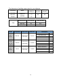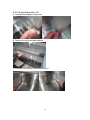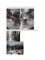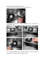
1
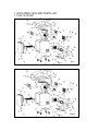
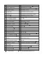
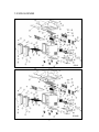
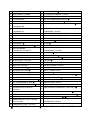
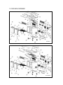
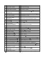
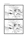
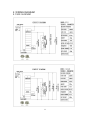
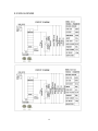
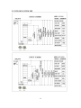
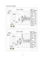
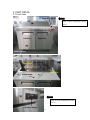
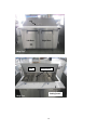
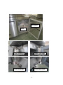
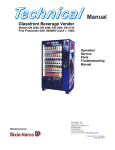
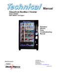
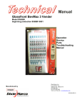
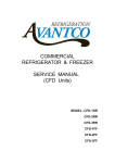
COMMERCIAL
REFRIGERATOR & FREEZER
SERVICE MANUAL
(SCL/SCLM)
MODEL: SCL1
SCL2
SCL2-60
SCL3
SCLM1
SCLM2
SCLM2-60
SCLM3
TABLE OF CONTENTS
1. EXPLODED VIEW AND PARTS LIST....................................... 3
1.1 SCL1 & SCLM1.................................................................. 3
1.2 SCL2 & SCLM2.................................................................. 5
1.3 SCL260 & SCLM260 .......................................................... 7
1.4 SCL3 & SCLM3.................................................................. 8
2. WIRING DIAGRAM ................................................................. 11
2.1 SCL1 & SCLM1................................................................ 11
2.2 SCL2 & SCLM2................................................................ 12
2.3 SCL260 & SCLM260 ........................................................ 13
2.4 SCL3 & SCLM3................................................................ 14
3. PART DETAIL ......................................................................... 15
3.1 Front view ........................................................................ 15
3.2 Back View ........................................................................ 19
3.3 Inner View ........................................................................ 21
4. CONTROLLER INSTRUCTION .............................................. 23
4.1 Refrigerator controller ...................................................... 23
5. REPLACEMENT OF MAIN PARTS ........................................ 26
5.1 Door ................................................................................. 26
5.2 Replacing the Temperature Display……………………… ..27
5.3 Compressor & Condenser unit ......................................... 28
5.4 Lids and evaporator unit ................................................... 31
6. CLEANING AND MAINTENANCE .......................................... 34
6.1 CLEANING....................................................................... 34
6.2 Maintenance .................................................................... 35
7. TROUBLESHOOTING ............................................................ 36
2
1. EXPLODED VIEW AND PARTS LIST
1.1 SCL1 & SCLM1
SCL1
SCLM1
3
1
CABINET: N/A
34
4" CASTER: 17819301
2
DOOR: 17817006
35
INSTALLATION BOARD SUPPORT
3
GASKET: 178GSKT17313
36
COMPRESSOR UNIT TRACK
4
178CARTRIDGE
37
COMPRESSOR UNIT INSTALLATION BOARD
5
HINGE AXIS: 17812251
38
CONDENSER: 17811501
6
7
BOTTOM RIGHT HINGE:
178HINGSCLBR
UPPER RIGHT HINGE:
178HINGSCLTR
39
40
CONDENSER FAN MOTOR: 17819194
CONDENSER FAN MOTOR BLADE: 17814791
8
TOP BOARD
41
CONDENSER FAN COVER: 17810515
9
MOUNT FOR CUTTING BOARD
42
FILTER FIXER
10
CUTTING BOARD: 178CBS972
(SCL1) 178CBSM728 (SCLM1)
43
FILTER
11
BACK COVER: 17816214/17813121
44
OUTER DRAIN PAN: 17817738
12
LID: 17813430/17818952
45
COMPRESSOR: 17817554
13
DOWEL: 17817446
46
SPLICE BOX
14
PLASTIC BOLT: 17817446
47
START CAPACITOR
15
NUT: 17817446
48
OVERLOAD PROTECTOR
16
SPLIT PIN: 17817446
49
STARTER
17
AIR DUCT SUPPORT
50
K STRIP-2 HOLES: 17814517
18
EVAPORATOR COVER
51
K STRIP-3 HOLES: 17815412
19
AIR RETURN COVER
52
K CLIP
20
INNER DRAIN PAN: 17813591
53
SHELF: 178SHELFSCL
21
EVAPORATOR:17812503
54
BACK GRILL
22
FAN MOTOR INSTALLATION PANEL
55
FAHR TEMP DISPLAY INSTALLATION BOARD
23
LEFT CLAPBOARD OF EVAP
56
FOAMING HOLE COVER
24
RIGHT CLAPBOARD OF EVAP
57
DRAIN TUBE(Φ16mm)
25
26
EVAPORATOR FAN MOTOR:
17813407
STAND OFF BRACKET:17818837
58
59
POWER CORD: 17810175
TEMPERATURE SENSOR 1 (THERMOSTAT):
17811959
27
THERMOSTAT INSTALLATION BOX
60
TEMP SENSOR 2(FAHRENHEIT TEMP DISP)
28
THERMOSTAT: 17815350
61
FAHRENHEIT TEMP DISPLAY: 17817225
29
POWER SWITCH: Green- 17810364
Red-17810365
62
TRANSFORMER FOR FAHRENHEIT TEMP DISPLAY
30
PAN BRACKET-15mm
63
TRANSFORMER HOLDER
31
PAN BRACKET-25mm: 17815874
64
AIR SHEILD BOARD 1
32
CASTER SUPPORT
65
AIR SHEILD BOARD 2
33
4" CASTER WITH BRAKE: 17816412
- Consult Factory
- Only Units Manufactured Before 6/1/15.
4
1.2 SCL2 & SCLM2
SCL2
SCLM2
5
1
CABINET: N/A
35
CASTER SUPPORT
2
RIGHT DOOR: 17810080
36
4" CASTER WITH BRAKE: 17816412
3
GASKET: 178GSKT11759
37
4" CASTER: 17819301
4
178CARTIRIDGE
38
INSTALLATION BOARD SUPPORT
5
HINGE AXIS: 17812251
39
COMPRESSOR UNIT TRACK
6
7
BOTTOM RIGHT HINGE:
178HINGSCLBR
UPPER RIGHT HINGE:
178HINGSCLTR
40
41
COMPRESSOR UNIT INSTALLATION BOARD
CONDENSER: 17813281
8
LEFT DOOR: 17810080
42
CONDENSER FAN MOTOR: 17810976
9
GASKET: 178GSKT11759
43
CONDENSER FAN MOTOR BLADE: 17814269
10
BOTTOM LEFT HINGE: 178HINGSCLBL
44
CONDENSER FAN COVER: 17810515
11
UPPER LEFT HINGE: 178HINGSCLTL
45
FILTER FIXER
12
TOP BOARD
46
FILTER
13
MOUNT FOR CUTTING BOARD
47
OUTER DRAIN PAN: 17817738
14
CUTTING BOARD:
178CBS1046/178CBSM747
48
COMPRESSOR: 17810635
15
BACK COVER: 17814129/17819918
49
SPLICE BOX
16
LID: 17813359/17819990
50
START CAPACITOR
17
DOWEL: 17817446
51
OVERLOAD PROTECTOR
18
PLASTIC BOLT: 17817446
52
STARTER
19
NUT: 17817446
53
K STRIP-2 HOLES: 17814517
20
SPLIT PIN: 17817446
54
K STRIP-3 HOLES: 17815412
21
AIR DUCT SUPPORT
55
K CLIP: 178CLIP
22
EVAPORATOR COVER
56
SHELF: 178SHELFSCL2
23
AIR RETURN COVER
57
BACK GRILL
24
INNER DRAIN PAN: 17814037
58
FAHR TEMP DISPLAY INSTALLATION BOARD
25
EVAPORATOR: 17814715
59
FOAMING HOLE COVER
26
FAN MOTOR INSTALLATION PANEL
60
DRAIN TUBE(Φ16mm): 17819999
27
LEFT CLAPBOARD OF EVAP
61
POWER CORD: 17810175
28
RIGHT CLAPBOARD OF EVAP
62
TEMPERATURE SENSOR 1 (THERMOSTAT): 17811959
29
EVAPORATOR FAN MOTOR:
17813407
63
TEMP SENSOR 2(FAHRENHEIT TEMP DISP)
30
STAND OFF BRACKET: 17818837
64
FAHRENHEIT TEMP DISPLAY: 17817225
31
THERMOSTAT INSTALLATION BOX
65
TRANSFORMER FOR FAHRENHEIT TEMP DISPLAY
32
THERMOSTAT: 17815350
66
TRANSFORMER HOLDER
33
34
POWER SWITCH: Green- 17810364
Red-17810365
67
PAN BRACKET-15/90mm
PAN BRACKET-25mm: 17815874
- Consult Factory
- Only Units Manufactured Before 6/1/15.
6
1.3 SCL260 & SCLM260
SCL260
SCLM260
7
1
CABINET: N/A
35
PAN BRACKET-25mm: 17815874
2
RIGHT DOOR: 17819424
36
CASTER SUPPORT
3
GASKET: 178GSKT19722
37
4" CASTER WITH BRAKE: 17816412
4
SPRING HINGE CARTRIDGE
38
4" CASTER: 17819301
5
HINGE AXIS COVER: 17812251
39
INSTALLATION BOARD SUPPORT
6
BOTTOM RIGHT HINGE:
COMPRESSOR UNIT TRACK
178HINGSCLBR
40
7
UPPER RIGHT HINGE: 178HINGSCLTR
41
COMPRESSOR UNIT INSTALLATION BOARD
8
LEFT DOOR: 17814620
42
CONDENSER: 17813281
9
GASKET: 178GSKT19722
43
CONDENSER FAN MOTOR: 17810976
178HINGSCLBL
44
CONDENSER FAN MOTOR BLADE: 17814269
11
UPPER LEFT HINGE: 178HINGSCLTL
45
CONDENSER FAN MOTOR COVER: 17810515
12
TOP BOARD
46
FILTER FIXER
13
FIXER FOR CUTTING BOARD
47
FILTER
178CBS1060/178CBSM760
48
OUTER DRAIN PAN: 17817738
15
BACK COVER: 17819580/17819796
49
COMPRESSOR: 17810635
16
LID: 17815722/17819831
50
SPLICE BOX
17
DOWEL: 17817446
51
START CAPACITOR
18
PLASTIC BOLT: 17817446
52
OVERLOAD PROTECTOR
19
NUT: 17817446
53
STARTER
20
SPLIT PIN: 17817446
54
K STRIP-2 HOLES: 17814517
21
AIR DUCT SUPPORT
55
K STRIP-3 HOLES: 17810635
22
EVAPORATOR COVER
56
K CLIP: 178CLIP
23
AIR RETURN COVER
57
SHELF:178SHELFSC26
24
INNER DRAIN PAN: 17812261
58
BACK GRILL
25
EVAPORATOR: 17816297
59
FAHR TEMP DISPLAY INSTALLATION BOARD
26
FAN MOTOR INSTALL PANEL
60
FOAMING HOLE COVER
27
LEFT CLAPBOARD OF EVAP
61
DRAIN TUBE(16mm): 17819999
28
RIGHT CLAPBOARD OF EVAP
62
POWER CORD: 17810175
29
EVAPORATOR FAN MOTOR: 17813407
63
TEMPERATURE SENSOR 1 (THERMOSTAT)
30
STAND OFF BRACKET
64
TEMP SENSOR 2(FAHRENHEIT TEMP DISP)
31
THERMOSTAT INSTALLATION BOX
65
FAHRENHEIT TEMP DISPLAY: 17817225
32
THERMOSTAT: 17815350
10
14
33
34
BOTTOM LEFT HINGE:
CUTTING BOARD:
TRANSFORMER FOR FAHRENHEIT TEMP DISPLAY:
66
POWER SWITCH: Green- 17810364
Red-17810365
17813417
TRANSFORMER HOLDER
67
PAN BRACKET-15/108mm
- Consult Factory
- Only Units Manufactured Before 6/1/15.
8
1.4 SCL3& SCLM3
SCL3
SCLM3
9
1
CABINET: N/A
36
CASTER SUPPORT
2
RIGHT DOOR: 17814618
37
4" CASTER WITH BRAKE: 17816412
3
GASKET: 178GSKT15178
38
4" CASTER: 17819301
4
SPRING HINGE CARTRIDGE
39
INSTALLATION BOARD SUPPORT
5
HINGE AXIS COVER: 17812251
40
COMPRESSOR UNIT TRACK
6
BOTTOM RIGHT HINGE: 178HINGSCLBR
41
COMPRESSOR UNIT INSTALLATION BOARD
7
UPPER RIGHT HINGE: 178HINGSCLTR
42
CONDENSER: 17813281
8
LEFT DOOR: 17810267
43
CONDENSER FAN MOTOR: 17810976
9
GASKET:178GSKT15178
44
CONDENSER FAN MOTOR BLADE: 17814269
10
BOTTOM LEFT HINGE: 178HINGSCLBL
45
CONDENSER FAN COVER: 17810515
11
UPPER LEFT HINGE: 178HINGSCLTL
46
FILTER MOUNT
12
TOP BOARD
47
FILTER
13
MOUNT FOR CUTTING BOARD
48
OUTER DRAIN PAN: 17817738
14
CUTTING BOARD: 178CBS1070/178CBSM770
49
COMPRESSOR: 17818892
15-1
BACK COVER 1 (BIGGER ONE): 17819395
50
SPLICE BOX
15-2
BACK COVER 2(SMALLER ONE): 17817168
51
START CAPACITOR
16-1
LID 1 (BIGGER ONE): 17815296
52
OVERLOAD PROTECTOR
16-2
LID 2 (SMALLER ONE): 17811362
53
STARTER
17
DOWEL: 17817446
54
K STRIP-2 HOLES: 17814517
18
PLASTIC BOLT: 17817446
55
K STRIP-3 HOLES: 17815412
19
NUT: 17817446
56
K CLIP: 178CLIP
20
SPLIT PIN: 17817446
57
SHELF: 178SHELFSC3
21
AIR DUCT SUPPORT
58
BACK GRILL
22
EVAPORATOR COVER
59
FAHRENHEIT TEMP DISPLAY INSTALLATION BOARD
23
AIR RETURN COVER
60
FOAMING HOLE COVER
24
INNER DRAIN PAN
61
DRAIN TUBE(16mm): 17819999
25
EVAPORATOR: 17816297
62
POWER CORD: 17810175
26
FAN MOTOR INSTALLATION PANEL
63
TEMPERATURE SENSOR 1 (THERMOSTAT): 17811959
27
LEFT CLAPBOARD OF EVAP
64
TEMPERATURE SENSOR 2(FAHRENHEIT TEMP DISP)
28
RIGHT CLAPBOARD OF EVAP
65
FAHRENHEIT TEMP DISPLAY: 17817225
29
EVAPORATOR FAN MOTOR: 17813407
66
TRANSFORMER FOR FAHRENHEIT TEMP DISPLAY
30
STAND OFF BRACKET: 17818837
67
TRANSFORMER HOLDER
31
THERMOSTAT INSTALLATION BOX
68
MIDDLE SMALL CASTER SUPPORT: N/A
32
THERMOSTAT: 17815350
69
MIDDLE SMALL CASTER: N/A
33
POWER SWITCH: Green-17810364 Red-17810365
70
PAN BRACKET-90mm
34
PAN BRACKET-15mm
71
TOP BOARD PLATE
35
PAN BRACKET-25mm: 17815874
72
WINDSHIELD STRIP
- Consult Factory
- Only Units Manufactured Before 6/1/15.
10
2. WIRING DIAGRAM
2.1 SCL1 & SCLM1
11
2.2 SCL2 & SCLM2
12
2.3 SCL260 & SCLM 260
13
2.4 SCL3 & SCLM3
14
3. PART DETAIL
3.1 Front view
Fahrenheit display
Lid
Only on units manufactured before
6/1/15.
Left Door
Right Door
Salad prep table
25mm wide
Pan bracket
15mm wide
Cutting board
Only on units manufactured before
6/1/15.
Fahrenheit display
15
Lid
Left Door
Right Door
Mega Top
Lid
Pan bracket
Cutting board
Mega Top
16
Door gasket
Shelf
Upper left hinge
Upper right hinge
Lower left hinge
Lower right hinge
17
Upper left hinge
Lower left hinge
Upper right hinge
Lower right hinge
Lid Hinge Pin Assembly
18
3.2 Back View
Back cover
Back grille
Controller
&
Power switch
Power cord
19
Outer drain
pan
Compressor
component
Condenser
component
Transformer
for Temp.
F Temperature
Display
Capillary Tube
One door prep table
Only on units manufactured before
6/1/15.
20
3.3 Inner View
Air return cover
Evaporator
cover
Shelf
Air return
cover
Only on units manufactured before
6/1/15.
White: Temp sensor for
F Temperature display
Black: Temp sensor for
digital controller
21
One motor
Evaporator fan motor
Inner drain pan
Evaporator
Three motors
Four motors
motors
22
4. CONTROLLER INSTRUCTION
4.1 Refrigerator controller
Digital controller model: PJEZ
Display and functions
During normal operation, the controller displays the value of the probe set using
parameter/4(=1 ambient probe, default, = 2 second probe, = 3 third probe).In addition, the
display has LEDs that indicate the activation of the control functions (see Table 1),while the 3
buttons can be used to activate/deactivate some of the functions(see Table 2).
23
Setting the desired temperature
1. Press SET for 1 s, the set value will start flashing after a few moments;
2. Increase or decrease the value using UP or DOWN;
3. Press SET to confirm the new value.
Switching the device ON/OFF
Press UP for more than 3 s. The control and defrost algorithms are now disabled and the
controller displays the message “OFF” alternating with the temperature read by the set probe.
Manual defrost
Press DOWN for more than 3 s (the defrost starts only if the temperature conditions are valid).
Continuous cycle
Press UP and DOWN together for more than 3 s.
Access and setting type F (frequent) and type C (configuration) parameters
1. Press SET for 3 s (the display will show ”PS”);
2.To access the type F and C parameter menu, press SET ,enter the password “22”
using UP/DOWN, press SET to confirm;
To access the F parameter menu only, press SET (without entering the password);
3. Scroll inside the parameter menu using UP/DOWN;
4. To display/set the values of the parameter displayed, press SET, then UP/DOWN and
finally SET to confirm the changes (returning to the parameter menu).
To save all the new values and exit the parameter menu, press SET for 3 s;
To exit the menu without saving the changed values (exit by timeout) do not press any button
for at least 60 s.
24
Correct Settings for CAREL Controllers (115V)
MODE
PJEZ(REFRIG)
DISPLAY
/5
1
TEMPERATURE UNIT F/C
/c1
0
CABINET OFFSET
/c2
0
EVAP OFFSET
St
33
USER SET POINT
rd
7
DIFFERENTIAL
r1
33
LOW LIMIT
r2
43
HIGH LIMIT
c0
2
COMPRESSOR DELAY
dI
3
DEFROST INTERVAL TIME
dt1
43
DEFROST TERMINATION TEMP
dP1
20
MAX DEFROST DURATION
F0
N/A
FAN OPERATING FUNCTION
F1
N/A
FAN STARTING TEMPERATURE
F2
N/A
FAN STOPS WHEN COMPRESSOR STOPS
F3
N/A
FAN MODE DURING DEFROSTING
25
5. REPLACEMENT OF MAIN PARTS
CAUTION!!!
Before beginning with replacement work make sure the device has
been disconnected from the power socket (pull the power plug) and
has been cooled down.
5.1 Door
A. Unscrew the bottom hinge. Be sure to have another person hold the door to
prevent it from falling.
After unscrewing the bottom hinge, you can pull down the door from the top hinge
and replace the door/hinge/spring hinge/gasket.
B. Install a new door. Assemble the lower hinge with the spring hinge first.
26
C. Match the upper hinge and hinge axis, and assemble the bottom hinge.
5.2 Replacing the Temperature Display
(Only for units manufactured before 6/1/15.)
E. Unscrew the Fahrenheit temp display board
F. Disconnect the wire and replace the Fahrenheit temp display
27
5.3 Compressor & Condenser unit
A. Disassemble the back grille and controller installation box
B. Remove the back grille
C. Disconnect the wire & cable tie, unscrew the screws.
28
D. Unscrew the compressor unit installation board
E. Cut the cable tie used to attach the capillary tube so that you can pull out the
compressor unit installation board and replace the main parts here.
29
The dimensions of welding copper pipes for your reference:
Compressor
Maker
NE6170Z
NE6187Z
T6213Z
EMBRACO
ASPERA
SCL 1
SCLM 1
SCL 260
SCLM 3
Φ8
Φ6
Outlet line(mm)
φ25×140
φ25×187
φ8
φ8
Φ2.5
Φ3.2
Compressor
NE6170Z
Parts name
COMPRESSOR
COMPONENT
Parts NO.
17817554
NE6187Z
COMPRESSOR
COMPONENT
17810635
SCLM 260
SCL 3
Discharge
line(mm)
Inlet line(mm)
SCL2
SCLM 2
Suction
line (mm)
Dimension(mm)
Filter
Model
Compressor
power hp
1/4
1/3
1/2
T6213Z
COMPRESSOR
COMPONENT
17818892
30
Description
START CAPACITOR
2252349
RUN CAPACITOR
/
STARTER
2334101
OVERLOAD PROTECTOR
2319080
START CAPACITOR
2252335
RUN CAPACITOR
/
STARTER
2283001
OVERLOAD PROTECTOR
2321070
START CAPACITOR
2252335
RUN CAPACITOR
/
STARTER
2283041
OVERLOAD PROTECTOR
2285096
5.4 Lids and evaporator unit
A. Unscrew the hinge pin component
B. Remove the lid(s) and pan brackets.
C. Unscrew the air return cover and remove it.
31
D. Unscrew the evaporator fan cover after removing the air return cover
E. Unscrew the temperature sensor mount and remove the evaporator fan cover
32
You can replace evaporator fan motor here.
F. Disconnect the wire connection for the evaporator fan motor
G. Unscrew the evaporator fan motor installation board. Disconnect the
evaporator fan motor
You can replace evaporator unit and inner drain pan here after removing the
evaporator fan motor and fan motor installation board
33
6. CLEANING AND MAINTENANCE
6.1 CLEANING
CAUTION!!! Before cleaning the cabinet, ensure it is disconnected from the main
power supply.
A. Clean exterior and interior of the device with a moist and soft cloth. Dry and
polish the device with a soft and dry cloth after cleaning.
B. Use a vacuum cleaner and soft brush to carefully clean the surface of the
condenser unit.
34
Tips for cleaning
1. Clean the device regularly.
2. Never use harsh cleaning substances such as scouring powder or cleaners
containing alcohol or solvents that could damage the device’s surface
3. Condenser unit must be always keep clean and free of dust. If not, the device
will not cool properly.
4. Never use a stiff brush to clean the device.
5. Do not pressure wash the unit.
6.2 Maintenance
1. Clean the exterior and interior of the device and condenser unit regularly.
2. Check the main connection cable for damage from time to time. Never operate
the device when the cable is damaged. A damaged cable must immediately be
replaced by customer service or a qualified electrician.
3. In case of damage or malfunction, please contact our customer service center
at 1-800-678-5517.
4. If the device is not going to be used for a long period time, remove the plug
from its socket and remove the food in the device. Clean and dry the device
thoroughly.
5. Only a qualified technician and using original spare parts and accessories
should carry out repairs and maintenance of the device. Do not attempt to repair
the device yourself.
35
7. TROUBLESHOOTING
TROUBLESHOOTING
GUIDE
PROBLEM
Before calling for service, review this list. It may save you time and expense. This list includes common occurrences that are not
the result of defective workmanship or materials in this appliance.
CAUSE
CORRECTION
APPLIANCE OPERATION
Appliance does not run
·Appliance is plugged into a circuit that has a
·Use another circuit. If you are unsure about the outlet, have it checked by
ground fault
a certified technician
·Temperature control is in the "OFF" position.
·See "controller instruction"
·Appliance may not be plugged in, or plug may be
·Ensure plug is tightly pushed into outlet
loose.
·House fuse blown or tripped circuit breaker.
·Check/replace fuse with a 15 amp time delay fuse. Reset circuit breaker
·Power outage
·Check house lights. Call local Electric Company
·Room or outside weather is hot.
·It's normal for the appliance to work harder under these conditions.
·Appliance has recently been disconnected for a
·It takes hours for the appliance to cool down
period of time
completely.
·Large amount of warm or hot food have been
·Warm food will cause appliance to run more until the desired
stored recently.
temperature is reached
·Door is opened too frequently or kept open too
·Warm air entering the appliance causes it to run
long or slightly open
more. Open the door less often. Completely close the door
Appliance runs too
much or too long
·Set the controller to a warmer setting. Allow several hours for the
·Temperature control is set too low
temperature to stabilize
·Appliance gaskets are dirty, worn, cracked or
·Clean or change gasket. Leaks in the lid seal will cause appliance to run
poorly fitted.
longer in order to maintain desired temperature
Interior appliance
· Set the controller to a warmer setting. Allow several hours for the
·Temperature control is set too low
temperature is too cold
temperature to stabilize
Set the controller to a colder setting. Allow several hours for the
·Temperature control is set too warm.
temperature to stabilize
·Door is opened too frequently or kept open too
·Warm air entering the appliance causes it to run more. Open the door
Interior appliance
long.
less often
temperature is too
·Appliance door may be slightly open
·Completely close the door
warm.
·Large amount of warm or hot food have been
·Wait until the appliance has had a chance to reach its selected
stored recently.
temperature.
·Appliance has recently been disconnected for a
·Appliance requires hours to cool down completely.
period of time
Appliance external
·The external appliance walls can be as much as
·This is normal while the compressor works to
30ºF warmer than room temperature.
transfer heat from inside the appliance cabinet
surface temperature is
warm.
36
PROBLEM
CAUSE
CORRECTION
SOUND AND NOISE
Louder sound
·Modern appliances have increased storage capacity
levels whenever
and more stable temperatures. They require heavy
appliance is on.
duty compressors.
·This is normal. When the surrounding noise level is low, you might hear the
compressor running while it cools the interior.
Louder sound
levels when
·Appliance operates at higher pressure during the
·This is normal. Sound will level off or disappear as appliance continues to
compressor
start of the ON cycle.
run.
·Metal parts undergo expansion and contraction, as
·This is normal. Sound will level off or disappear as appliance continues to
in hot water pipes
run.
·Refrigerant(used to cool appliance) is circulating
·This is normal.
·Appliance is not level. It rocks on the floor when it is
·Level the appliance by putting wood or metal shims under part of the
moved
appliance.
comes on.
Popping or
cracking
sound when
compressor
comes on
Bubbling or
gurgling sound
Vibrating or
rattling noise.
·Ensure floor can adequately support appliance. Level the appliance by
·Floor is uneven or weak
putting wood or metal shims under part of the appliance.
·Appliance is touching the wall
·Re-level appliance or move appliance slightly
WATER / MOISTURE / FROST INSIDE APPLIANCE
·Weather is hot and humid, which increases internal
·This is normal.
Moisture forms
rate of frost build up.
on inside
·Door is slightly open.
appliance walls.
·Door is kept open too long or is opened too
·Make sure the door is closed completely
·Open the door less often
frequently.
ODOR IN APPLIANCE
Odors in
appliance
·Interior needs to be cleaned
·Clean interior with sponge, warm water, and baking soda.
·Foods with strong odors are in the appliance.
·Cover the food tightly.
·Appliance is not level. It rocks on the floor when it is
·Level the appliance by putting wood or metal shims under part of the
moved slightly
appliance.
DOOR PROBLEMS
Door will not
close.
·Ensure floor can adequately support appliance. Level the appliance by
·Floor is uneven or weak.
putting wood or metal shims under part of the appliance
LIGHTING PROBLEMS
Light bulb is not
on.
·The fluorescent lamp or light bulb is burned out.
·Turn off the power and replace a new lamp
·No electric current is reaching the appliance
·Check the plug and house light
37
38