1
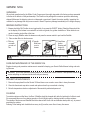
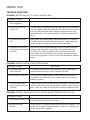
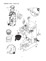
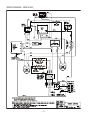
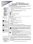
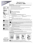
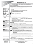
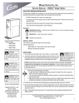
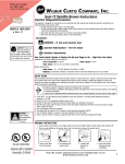
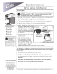
Wilbur Curtis Company, Inc.
Service Manual – GEM-120A Satellite Brewer
Important Safeguards/Symbols
This equipment is designed for commercial use. Any servicing other than cleaning and routine maintenance should be
performed by an authorized Wilbur Curtis Company Service Technician.
• DO NOT immerse the unit in water or any other liquid
• To reduce the risk of fire or electric shock, DO NOT open service panels. There are no user serviceable parts inside.
• Keep hands and other items away from hot areas of the unit during operation.
• Never clean with scouring powders or harsh chemicals.
Symbols:
WARNINGS – To help avoid personal injury
Important Notes/Cautions – from the factory
Sanitation Requirements
INSTALLATION
Model:
● GEM-120A
This Curtis unit is pre-set and ready to go from the factory.
Factory settings for this unit are:
• Brew Temperature = 200°F
• Brew Volume = Set to vessel requirements (1 Gallon).
CAUTION:
Equipment must be
installed to comply
with applicable federal, state,
and local plumbing/electrical
codes.
CAUTION: Follow
this setup procedure
before attempting
to use this unit. Failure to
follow these instructions can
result in injury and/or void of
warranty.
CAUTION: DO NOT
connect the unit to
hot water supply.
The inlet valve is not rated for
hot water.
C
ISO 9001:2008 REGISTERED
WILBUR CURTIS CO., INC.
6913 West Acco Street
Montebello, CA 90640-5403
For the latest information go to
www.wilburcurtis.com
Tel: 800-421-6150
Fax: 323-837-2410
System Requirements:
• Water Supply 20 – 90 PSI (minimum flow rate of 1 gpm)
• Electrical: See electrical schematic.
SETUP STEPS
1. The unit should be level (left to right - front to back), on a secure surface.
2. Connect the water line to the water inlet fitting on the rear of the unit. Water volume flow to the machine should be
consistent. Use tubing sized sufficiently to provide a minimum flow rate of one gallon per minute.
NOTE: A water filtration system must be used to help maintain trouble-free operation. In areas with extremely hard
water, we highly recommend the use of a Curtis approved water filter. For our full line of filters, please log on to
www.wilburcurtis.com. A water filtration system will greatly prolong the life of the unit and enhance the quality and
taste of the product.
NSF International requires the following water connection:
1. A quick disconnect or additional coiled tubing (at least 2x the depth of the unit) is required so that the unit
can be moved for cleaning.
2. This unit must be installed with adequate backflow protection to comply with applicable federal, state and
local codes.
3. Water pipe connections and fixtures directly connected to a portable water supply shall be sized, installed
and maintained in accordance with federal, state, and local codes.
3. Connect the unit to electrical outlet with appropriate amperage rating (see serial tag on machine).
4. Once power has been supplied to the unit, flip the toggle switch to the ‘ON’ position (located on the rear of the unit),
the water tank will begin to fill. When the water level in the tank reaches the probe, the heating element(s) will turn on.
5. Water in the heating tank will require approximately a half hour before reaching operating temperature (factory setting of
200°F). Where applicable, turn on the Universal Control Module (UCM). When the unit reaches operating temperature,
it will display “READY TO BREW”.
For the latest specifications and information go to www.wilburcurtis.com
Technical Support: 1-800-995-0417 M-F 5:30am-4:00pm PT
Email: [email protected]
GEMINI 120A
UNPACKING
All products manufactured by the Wilbur Curtis Company are thoroughly inspected at the factory and are warranted
to be free of all defects or faulty workmanship. The Gemini unit is packaged for maximum protection while being
shipped. Make sure the shipping carton is not damaged or punctured. Unpack the carton carefully, inspecting the
contents for any damage that may have occurred in transit. Report any damage immediately to the freight company.
BREWING INSTRUCTIONS
1. Brewer should be ON (Confirm at rear toggle switch, then press the ON/OFF button). Ready-to-Brew should be
on the display. If the brewer is connected to an InterLock grinder, the grinder should be on. When Interlock connection is made, grind coffee at this time.
2. Place an empty Satellite under the brewcone and press the warmer switch to pre-heat the Satellite.
3. Place a clean filter into the brewcone.
4. Fill brewcone with ground coffee.
5.Transfer
filled brew
cone to
brewer.
6.Press Brew
button.
Brewing will
begin immediately.
WARNING: TO AVOID SCALDING, Do not remove brewcone while brew light is flashing.
CARE AND MAINTENANCE OF THE GEMINI 120A
Regular cleaning and preventive maintenance is essential in keeping your Gemini Coffee Brewer looking and working like new.
WARNING Do not use cleansers, liquids, bleaches, or powder that contain chlorine. These products cause corrosion and pitting on stainless steel and will void your warranty.
PREVENTIVE MAINTENANCE
1. Remove the sprayhead from the Gemini 120A and clean once a week or more often in heavy lime areas.
2. Clean the faucet seat cups twice a week and replace when they are cracked or leaking.
3. Periodic temperature checks or adjustment of thermostat by authorized personnel.
CLEANING
To maintain optimum coffee flavor, the Gem 3 Satellite should be cleaned daily after the last batch of coffee is used.
We recommend the use of urn cleaning powder or Scotch Bright pads for cleaning inside the coffee container.
The outside of the brewer and Satellite should be cleaned with a soft cloth and stainless steel polish only, to prevent
scratching the surface.
Deliming of the heating tank should be done every six (6) months; more often in heavy lime areas.
-2-
GEMINI 120A
SETTING THE WC-603-101 BREW TIMER
Adjustment of the timer is made on a calibrated dial with a range from 0 to 100.
This is a range of 2 to 20 minutes. The front control panel has a brew selector
switch marked FULL and 1/2.
To change the setting, flip the brew selector switch to FULL. Locate the brew
timer, inside the top cover. Rotate timer arrow to the right to increase the brew
time, rotate to the left to decrease the brewing time. The indicator dial is normally
set pointing at 25. This setting is intended to deliver one gallon of water (brew 24
cups) per brew cycle. To brew ½ gallon, flip the brew selector switch to 1/2.
SETTING TIMER WC-603RDS
This timer is the previous version of the WC-603-101,
above. The timer is mounted inside the upper compartment with the brew selector knob protruding from
the center of the front panel (see illustration, left). The
brewer is designed to brew 24 cups (one gallon maximum). Adjustment of the timer is made on the timer
calibration dial. The knob indicator must be set at the
480 second mark on the dial. On the front panel, the
brew selector switch should be at 2. This setting will
deliver one gallon of water (brew 24 cups) per brew
cycle. To brew 12 cups, simply turn the brew selector
knob to 1. If finer adjustments are needed, rotate timer
knob to the right to increase the brew time, rotate to
the left to decrease the brewing time.
ROUGH-IN DRAWING
-3-
GEMINI 120A
TROUBLE SHOOTING
PROBLEM: WATER DOES NOT FLOW INTO HEATING TANK
SOLUTION
POSSIBLE CAUSE
1. Water line turned off or filter clogged up.
Open the water line and make sure water flows to the brewer.
2. Water inlet valve coil burned out
Turn off brewer. Disconnect wires from water inlet coil terminals and
connect a power cord to the terminals. Plug cord into a 110v outlet
and verify that water flow when plugged in and stops when cord
is disconnected. If valve does not respond to this test, replace the
valve.
3. Grounded probe (item #5)
When water in the heating tank is below the probe tip, yet water is
not refilling, pull the wire off the probe terminal. If water starts flowing into the tank, find ground, clean or replace the probe.
4. Defective or burned out water level control board (item #3)
Pull the wire from the probe terminal. With a volt meter, check the
voltage at the water inlet coil terminals. This should read 110 to
115 volts. If no voltage is present, check the water level control
board. Make sure that the back of the board is grounded securely
to the mounting bracket. Check for loose wire connections. Replace
board.
PROBLEM: WATER IN HEATING TANK OVERFLOWING
POSSIBLE CAUSE
SOLUTION
5. Defective water inlet valve (item #9)
Turn power off and observe the water level in the heating tank. If
water continues to flow in, clean or replace the valve.
6. Probe limed up (item #5)
Pull wire off from probe terminal. Touch the water tank shell with
the terminal at the end of this wire. If water stops flowing, clean or
replace the probe.
7. Loose or ungrounded water level control board (item #3)
If probe is okay, check the water level control board. The water level
control board must be securely grounded. Check for loose connections. Check for voltage at the inlet valve terminals. Replace board.
PROBLEM: WATER IN TANK DOES NOT GET HOT OR WATER TEMPERATURE TOO LOW
SOLUTION
POSSIBLE CAUSE
8. Thermostat is off (item #10)
Check the thermostat to make sure it is in the ON position. Turn the
thermostat stem clockwise until it stops.
9. Burned out heating Check element for continuity and/or check with clamp ammeter. This
element.
should show a reading of approximately 15 amps. If no power is going through element, replace it.
-4-
GEMINI 120A
PROBLEM: WATER IN TANK DOES NOT GET HOT OR WATER TEMPERATURE TOO LOW
SOLUTION
POSSIBLE CAUSE
10. Defective thermostat
Thermostat may be cutting off before the water temperature reaches
operating temperature. Do not try to reset the thermostat. Replace it.
PROBLEM: WATER NOT FLOWING FROM SPRAYHEAD.
SOLUTION
POSSIBLE CAUSE
11. Water level is too low in heating tank
Check water level in tank. If water is not flowing into the tank, review steps 1 thru 4, previous page.
12. Defective brew switch (item #41)
Check the continuity between terminals 5B and 4B when the BREW
switch is pressed. If there is no continuity, replace the switch.
13. Defective timer (item #2).
Make sure the timer is receiving 110 to 120 volts. You can verify
this by taking a reading with your meter at the end of the YELLOW
wire on terminal 5B of the ON/OFF switch and at terminal A of the
timer. When the timer is activated by the brew switch, you should
read 110 to 120 volts across terminals 6 and A of the timer. The
RED wire on terminal 6 supplies power to open the dump valve. If
no voltage is present, replace the timer.
14. Burned out dump valve coil (item #34)
If the timer works when the brew switch is pressed, then check the
dump valve using a voltmeter on the terminals. If it shows 110 to
120 volts but no water flows through the valve, clean out the valve
or replace the coil.
-5-
GEMINI 120A Parts List
29
5
11
30
26
3
18
7
25
33
10
18
6
16
15
13
8
15
1
17
12
23
14
19
9
4
21
B
24
32
20
27
22
28
B
31
-6-
GEMINI 120A Parts List
Item
Nº
1
2
2A
3
4
5
6
7
7A
8
9
10
11
12
13
14
14A
15
16
17
18
19
20
21
22
23
24
25
26
27
28
29
30
30A
31
32
33
33A
Part
Nº
Description
WC-3621
WC- 603RDS
WC- 603-101
WC- 608
WC-2936
WC-37278
WC-3920T
WC- 904
WC- 906-04
WC-1200
WC- 826
WC- 517
WC-3763
WC- 817
WC-1809
WC- 202
WC- 203
WC- 114R
WC- 122
WC-2977-01
WC-5310
WC-5451
WC- 947
WC- 102
WC-3503
WC-3338
WC-5452
WC-5450
WC-43058
WC-3765
WC- 829
WC-37008
WC-5466
WC-54133
WC-3920B
WC-3518
WC- 523
WC- 522
BREW CONE, UNIVERSAL 7 1/8" BLK PLASTIC
TIMER, BREW SELECTOR 120V GEM-120A (OLDER UNITS)
TIMER, BREW SELECTOR 120V 2-20 MIN GEM-120A/RU'S (NEWER UNITS)
LEVEL CONTROL, WATER 120V
SPRAYHEAD, RED (.131 DIA)
KIT, LIQUID LEVEL PROBE GT
LABEL, TOP GEM 120A
ELEMENT, ENVELOPE HEATING w/SCREWS GEN USE
HEATING ELEMENT, 2000W, 220V W/JAM NUTS
POWER CORD, 6' 14/3 BLK SJTO
VALVE, INLET 1 GPM 120V 10W
THERMOSTAT, CAPILLARY SPST 277V 22A GEN USE
KIT, VALVE REPAIR FOR WC-866, WC-889, WC-816, WC-817, WC-818
VALVE, DELTROL DUMP RIGHT 120V.
FAUCET, HOT WATER W/JAM NUT
LIGHT, BREW 115V
LIGHT, BREW 220V
SWITCH, ROCKER 120V RED
SWITCH, ROCKER BREW 120V GREEN
FITTING ASSY, SPRAYHEAD PLATED TIN NICKEL
TUBE, 5/16" I.D. SILICONE GEN USE
WARMER DECK, NO ELEMENTS
ELEMENT, WARMER 90W, 115V
SWITCH, TOGGLE SPST 25A 125/250 VAC RESISTIVE
LEG, SCREW BUMPER 3/8-16 STD
KIT, BREW CONE W/BASKET SS 7 1/8" DELUXE BLK HANDLE (OPTIONAL)
COVER, FRONT GEM-120A/120P/230A/200R/300IL/600ILD
COVER, TOP D500, G230A, G120A, PTB
PLUG, DRAIN PP RED
KIT, VALVE REPAIR (USE ON WC-825 WC-826)
WASHER, .35 GPM .5" USE ON WC-825
LID ASSEMBLY, TANK
TANK, COMPLETE GEM-120A
TANK, COMPLETE GEM-120A 120/220V DV
LABEL, BOTTOM GEM-120A
LEG, GLIDE 3/8”-16 STUD SCREW
THERMOSTAT, MANUAL RESET 120/240 VAC 25A 220 DEG F MAX
THERMOSTAT, HI LIMIT HEATER CONTROL DPST 277V 40A
PAPER FILTERS
Part Number
CR- 12
CR- 10
Description
FILTER FOR BREW CONE WC-3338 (500/PKG)
FILTER FOR BREW CONE WC-3621 (1000/PKG)
-7-
ILLUSTRATED PARTS LIST GEM-3, 5, 8
5
6
7
8
11
4
9
2
12
1
17
10
15
14
13
3
INDEX PART
Nº
Nº
1 GEM-5
2 WC-1201
3 WC- 114R
4 GEM 3
5 WC-3307
5A WC-5622
6 WC-2102
7 WC-2010C
8 WC-2025
9 WC-2007
10 WC-1901
11 WC-1800
11A WC-1841
12 WC-3705
13 GEM 4
14 WC-3503
15 WC-37102
DESCRIPTION
SATELLITE WARMER STAND,115V
POWER CORD 6’ 18/3 BLK
SWITCH, ROCKER 120V RED
SATELLITE SERVER 1½ GAL
LID GEMINI SATELLITE
LID, SATELLITE PLASTIC GEM3 (OPTIONAL)
GAUGE GLASS ASSEMBLY, 8” C
SHIELD, 8 INCH GAUGE GLASS
GAUGE GLASS, 8 INCH
BRACKET, GAUGE GLASS FORMED
SHANK, FAUCET D&T CHROME
FAUCET S’ NONLOCKING
FAUCET, "ESP" BLACK NONLOCKING (OPTIONAL)
KIT FAUCET S’ SERIES
SATELLITE STAND
LEG, SCREW BUMPER 3/8"-16 STD
KIT, WARMER ELEMENT 100W 120VAC
-8-
WIRING DIAGRAM – GEM120A-10
-9-
WIRING DIAGRAM – GEM120A-63
- 10 -
WIRING DIAGRAM – GEM 5 & 8
- 11 -
Product Warranty Information
The Wilbur Curtis Company certifies that its products are free from defects in material and workmanship under normal use. The following
limited warranties and conditions apply:
3 Years, Parts and Labor, from Original Date of Purchase on digital control boards.
2 Years, Parts, from Original Date of Purchase on all other electrical components, fittings and tubing.
1 Year, Labor, from Original Date of Purchase on all electrical components, fittings and tubing.
Additionally, the Wilbur Curtis Company warrants its Grinding Burrs for Forty (40) months from date of purchase or 40,000 pounds of coffee,
whichever comes first. Stainless Steel components are warranted for two (2) years from date of purchase against leaking or pitting and
replacement parts are warranted for ninety (90) days from date of purchase or for the remainder of the limited warranty period of the equipment in which the component is installed.
All in-warranty service calls must have prior authorization. For Authorization, call the Technical Support Department at 1-800-995-0417. Effective date of this policy is April 1, 2003.
Additional conditions may apply. Go to www.wilburcurtis.com to view the full product warranty information.
CONDITIONS & EXCEPTIONS
The warranty covers original equipment at time of purchase only. The Wilbur Curtis Company, Inc., assumes no responsibility for substitute
replacement parts installed on Curtis equipment that have not been purchased from the
Wilbur Curtis Company, Inc. The Wilbur Curtis Company will not accept any responsibility if the following conditions are not met. The warranty
does not cover and is void under the following circumstances:
1) Improper operation of equipment: The equipment must be used for its designed and intended purpose and function.
2) Improper installation of equipment: This equipment must be installed by a professional technician and must comply with all local
electrical, mechanical and plumbing codes.
3) Improper voltage: Equipment must be installed at the voltage stated on the serial plate supplied with this equipment.
4) Improper water supply: This includes, but is not limited to, excessive or low water pressure, and inadequate or fluctuating water flow
rate.
5) Adjustments and cleaning: The resetting of safety thermostats and circuit breakers, programming and temperature adjustments are
the responsibility of the equipment owner. The owner is responsible for proper cleaning and regular maintenance of this equipment.
6) Damaged in transit: Equipment damaged in transit is the responsibility of the freight company and a claim should be made with the
carrier.
7) Abuse or neglect (including failure to periodically clean or remove lime accumulations): Manufacturer is not responsible for
variation in equipment operation due to excessive lime or local water conditions. The equipment must be maintained according to the
manufacturer’s recommendations.
8) Replacement of items subject to normal use and wear: This shall include, but is not limited to, light bulbs, shear disks, “0” rings,
gaskets, silicone tube, canister assemblies, whipper chambers and plates, mixing bowls, agitation assemblies and whipper propellers.
9) Repairs and/or Replacements are subject to our decision that the workmanship or parts were faulty and the defects showed up under
normal use. All labor shall be performed during regular working hours. Overtime charges are the responsibility of the owner. Charges
incurred by delays, waiting time, or operating restrictions that hinder the service technician’s ability to perform service is the responsibility of the owner of the equipment. This includes institutional and correctional facilities. The Wilbur Curtis Company will allow up to 100
miles, round trip, per in-warranty service call.
RETURN MERCHANDISE AUTHORIZATION: All claims under this warranty must be submitted to the Wilbur Curtis Company Technical
Support Department prior to performing any repair work or return of this equipment to the factory. All returned equipment must be repackaged properly in the original carton. No units will be accepted if they are damaged in transit due to improper packaging. NO UNITS OR
PARTS WILL BE ACCEPTED WITHOUT A RETURN MERCHANDISE AUTHORIZATION (RMA). RMA NUMBER MUST BE MARKED
ON THE CARTON OR SHIPPING LABEL. All in-warranty service calls must be performed by an authorized service agent. Call the
Wilbur Curtis Technical Support Department to find an agent near you.
WILBUR CURTIS CO., INC.
6913 Acco St., Montebello, CA 90640-5403 USA
Phone: 800/421-6150
Fax: 323-837-2410
Technical Support Phone: 800/995-0417 (M-F 5:30A - 4:00P PST)
Web Site: www.wilburcurtis.com
ECN 13180 . 5/16/[email protected]
E-Mail: [email protected]
Printed in U.S.A. 5/11 F-1903 Rev G