1
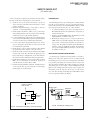
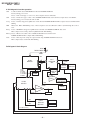
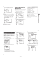
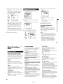
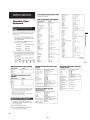
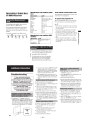
HISTORY INFORMATION FOR THE FOLLOWING MANUAL:
RA-4B CHASSIS
SERVICE MANUAL
MODEL NAME
KP-53HS10
KP-53HS10
KP-61HS10
KP-61HS10
☛
REMOTE COMMANDER
DESTINATION
CHASSIS NO.
RM-Y902
US
SCC-P40A-A
RM-Y902
Canadian
SCC-P40A-A
RM-Y902
US
SCC-P40B-A
RM-Y902
Canadian
SCC-P40B-A
:Updated Item
ORIGINAL MANUAL ISSUE DATE: 3/2000
ALL REVISIONS AND UPDATES TO THE ORIGINAL MANUAL ARE APPENDED TO THE END OF THE PDF FILE.
REVISION DATE
REVISION TYPE
SUBJECT
3/2000
6/2002
1/2004
No revisions or updates are applicable at this time.
Correction - 1
D Board Corrections - Q5031 Voltage; Waveforms.
Update
Updated P. 205 of Electrical Parts List - Corrected P/N for
F6105 and F6106
COLOR REAR VIDEO PROJECTOR
9-965-411-03
SERVICE MANUAL
MODEL
––––––––
COMMANDER DEST. CHASSIS NO.
––––––––––––––– –––––– ––––––––––––––
KP-53HS10
KP-53HS10
KP-61HS10
KP-61HS10
MUTING SYSTEM
OFF
FUNCTION
OFF
DVD/
VTR
RM-Y902
RM-Y902
RM-Y902
RM-Y902
POWER
DBS
CABLE
DVD/VTR DBS/CABLE
US
MODEL
––––––––
RA-4B CHASSIS
COMMANDER DEST. CHASSIS NO.
––––––––––––––– –––––– ––––––––––––––
SCC-P40A-A
Canadian SCC-P40A-A
US
SCC-P40B-A
Canadian SCC-P40B-A
TV
TV
FREEZE
AUDIO
SWAP POTITION
TV/DBS
GUIDE
CC
ZOOM IN
LEFT
RIGHT
ACTIVE
PICTURE
MODE
DISPLAY
TV/VIDEO
ANT
1
2
3
4
5
7
8
JUMP
6
9
ENTER
0
MENU
VOL
CH
RESET
TV
RM-Y902
KP-53HS10
KP-61HS10
COLOR REAR VIDEO PROJECTOR
∗ Please file according to model size. .......
53 61
KP-53HS10/61HS10
RM-Y902
RM-Y902
SPECIFICATIONS
–2–
KP-53HS10/61HS10
RM-Y902
RM-Y902
SAFETY CHECK-OUT
( US model only )
After correcting the original service problem, perfom the following safety checks before releasing the set to the customer:
l. Check the area of your repair for unsoldered or poorly-soldered connections. Check the entire board surface for solder
splashes and bridges.
2. Check the interboard wiring to ensure that no wires are
“pinched” or contact high-wattage resistors.
3. Check that all control knobs, shields, covers, ground straps,
and mounting hardware have been replaced. Be absolutely
certain that you have replaced all the insulators.
4. Look for unauthorized replacement parts, particularly transistors, that were installed during a previous repair. Point them
out to the customer and recommend their replacement.
5. Look for parts which, through functioning, show obvious
signs of deterioration. Point them out to the customer and
recom mend their replacement.
6. Check the line cords for cracks and abrasion. Recommend
the replacement of any such line cord to the customer.
7. Check the condition of the monopole antenna (if any). Make
sure the end is not broken off, and has the plastic cap on it.
Point out the danger of impalement on a broken antenna to
the customer, and recommend the antenna’s replacement.
8. Check the B+ and HV to see they are at the values specified.
Make sure your instruments are accurate;be suspicious of
your HV meter if sets always have low HV.
9. Check the antenna temminals, metal trim, “metallized” knobs,
screws, and all other exposed metal parts for AC leakage.
Check leakage as described below.
To Exposed Metal
Parts on Set
LEAKAGE TEST
The AC leakage from any exposed metal part to earth ground and
from all exposed metal parts to any exposed metal part having a
return to chassis, must not exceed 0.5mA (500 microampers) . Leakage current can be measured by any one of three methods.
1. A commercial leakage tester, such as the Simpson 229 or
RCA WT-540A. Follow the manufacturers’ instructions to
usc these instruments.
2. A battery-operated AC milliammeter. The Data Precision 245
digital multimeter is suitable for this job.
3. Measuring the voltage drop across a resistor by means of a
VOM or battery-operated AC voltmeter. The “limit” indication is 0.75V, so analog meters must have an accurate lowvoltage scale. The Simpson 250 and Sanwa SH-63Trd are
examples of a passive VOM that is suitable. NearIy all battery operated digital multimeters that have a 2V AC range
are suitable. (See Fig. A)
HOW TO FIND A GOOD EARTH GROUND
A cold-water pipe is guaranteed earth ground;the cover-plate retaining screw on most AC outlet boxes is also at earth ground. If
the retaining screw is to be used as your earth-ground, verify that it
is at ground by measuring the resistance between it and a coldwater pipe with an ohmmeter. The reading should be zero ohms. If
a cold-water pipe is not accessible, connect a 60-l00 watts trouble
light (not a neon lamp) between the hot side of the receptacle and
the retaining screw. Try both slots, if necessary, to locate the hot
side of the line, the lamp should light at normal brilliance if the
screw is at ground potential. (See Fig. B)
Trouble Light
AC Outlet Box
1.5 µ F
1.5k Ω
Ohmmeter
AC
voltmeter
(0.75V)
Cold-water Pipe
Earth Ground
Fig. B. Checking for earth ground.
Fig. A. Using an AC voltmeter to check AC leakage.
–3–
KP-53HS10/61HS10
RM-Y902
RM-Y902
SELF DIAGNOSIS FUNCTION
1.
2.
Summary of Self-Diagnosis Function
•
This device includes a self-diagnosis function.
•
In case of abnormalities, the TIMER/STAND BY indicator automatically blinks. It is possible to predict the abnormality location
by the number of blinks. The Instruction Manual describes blinking of the TIMER/STAND BY indicator.
•
If the symptom is not reproduced sometimes in case of a malfunction, there is recording of whether a malfunction was generated
or not. Operate the remote command to confirm the matter on the screen and to predict the location of the abnormality.
Diagnosis Items and Prediction of Malfunction Location
•
•
When a malfunction occurs the TIMER/STAND BY indicator only blinks for one of the following diagnosis items. In case of
two or more malfunctions, the item which first occurred blinks. If the malfunctions occurred simultaneously, the item with the
lower blink count blinks first.
The screen display displays the results regarding all the diagnosis items listed below. The display “ 0 ” means that no malfunctions occurred.
TIMER/STANDBY
Indicater
Number of blinks
Supposed malfunction
Condition
0
[Standby Power Supply System]
F601 open.
R607 open.
Q601 short circuit
[Main Power Supply System]
IC601 and R612 are broken.
VDR601 short-circuit
Cannot turn on the power.
LED doesn't blink.
2 times
Short circuit of power supply system in each circuit.
Goes to the standby mode
Short circuit of +B line
2 : +B OCP 000
+B OVP detection
3 times
IC6005 is broken.
IC6101 is broken.
Goes to the standby mode
Malfunction of power supply circuit
3 : +B OVP 000
Vertical deflection stop
4 times
IC5004(V out) is broken.
IC512 (VDSP) is broken.
Raster goes to one line horizontally.
4 : V Stop
000
Video out abnormality detection
5 times
Video out, IC7101, 7201, 7301 and others in C
board circuit.
Q510,516,524 (A board)
TIMER/STANDBY LED blinks approx. 30 seconds,
and then blinks for the self diagnosis.
5 : AKB
000
Horizontal deflection stop
6 times
Q5013 (H OUT) is broken.
IC507 (H Jungle) is broken.
Raster doesn't appear.
6 : H Stop
000
High voltage abnormality
detection
7 times
Q8008 is broken
Raster doesu't appear.
7 : HV
000
8 times
IC2601, 2602, 2603 are broken.
PS6103, 6104 are broken.
The sound is not out.
Goes to the standby mode
8 : A u d io
000
Diagnosis item
• Power not ON
+B OCP detection
Audio abnormality detection
Self-diagnosis
screen display,
Diagnosis item: Results
* : 000 the range of values for number of operations is 000-255. For 256 or higher there is
no count up and the number remains at 255.
3.
Blinking count display of TIMER/STAND BY indicator
* One blink is not used for self-diagnosis.
< FRONT PANEL >
•EXAMPLE
<Diagnosis Items> <Number of Blinks>
• +B overcurrent
2 times
• +B overvoltage
3 times
• Vertical deflection stop
4 times
Lamp ON : 0.3 seconds
Lamp OFF : 0.3 seconds
Lamp OFF :
3.0 seconds
TIMER/STAND BY indicator
Release of TIMER/STAND BY indicator blinking.
• The TIMER/STAND BY indicator blinking display is released by turning OFF the power switch
on the TV main unit or removing the plug from the power.
–4–
KP-53HS10/61HS10
RM-Y902
4.
Self-diagnosis screen displays
•
In cases of malfunctions where it is not possible to determine the symptom such as when the power goes off occasionally or when
the screen disappears occasionally, there is a screen display on whether the malfunction occurred or not in the past (and whether
the detection circuit operated or not) in order to allow confirmation.
<Screen Display Method>
• Quickly press the remote command button in the following order from the standby state.
DISPLAY b Channel 5 b VOL – b POWER
˘
Be aware that this differs from the method of
entering the service mode (volume + ).
Self-diagnosis screen display
Self Check
2 : +B OCP
3 : +B OVP
4 : V Stop
5 : AKB
6 : H Stop
7 : HV
8 : Audio
9 : WDT
5.
RM-Y902
000
000
000
000
000
000
000
000
÷
2 : +B OCP
000
000 the range of values for number of
operations is 000-255.
For 256 or higher there is no count up
Diagnosis
and the number remains at 255.
Results
Self-Diagnosis Screen Display
•
The results display is not automatically cleared. In case of repairs and after repairs, check the self-diagnosis screen and be sure
•
to return the results display to “ 0 ”.
If the results display is not returned to “ 0 ” it will not be possible to judge a new malfunction after completing repairs.
<Method of Clearing Results Display>
1. Power off (Set to the standby mode)
2. DISPLAY b Channel
3. Channel
5
b VOL +
b
POWER
(Service Mode)
8 b ENTER (Test reset = Factory preset condition)
<Method of Ending Self Diagnosis Screen>
• When ending the self-diagnosis screen completely, turn the power switch OFF on the remote commander or the main unit.
–5–
KP-53HS10/61HS10
RM-Y902
RM-Y902
6. Self-diagnosis function operation
OCP
Low B and +B line detect DET SHORT, and shut-down POWER ON RELAY.
Reset by turning power on/off.
OVP
In case of +B is loaded approx. 1.5A or more, microcomputer detects it via IC6102.
In case of +B becomes approx. 150V or more, POWER ON RELAY shuts down and microcomputer detects it via IC6102.
V Stop
Reset by turning power on/off just the same as OCP.
In case of V Drive disappeared, Q5005 detecs it and shut-down POWER ON RELAY. Microcomputer detects it and makes LED
AKB
blinking.
IK detection. Makes LED blinking in case of microcomputer doesn’t detect IK returns of IC511 (CXA2101AQ) 30 seconds or
H Stop
more.
In case of H DRIVE is disappeared, Q5006 detects it and shut-down POWER ON RELAY shuts down.
Microcomputer receives H Stop data from Q5006 and makes LED blinking.
HV Stop In case of HV becomes 33KV or more. IC8006 and IC8010 detect it and shut-down
Audio
POWER ON RELAY. Microcomputer makes LED blinking.
In case of DC component overlaps the output of Audio Amp., POWER ON RELAY shuts down.
Microcomputer detects it and makes LED blinking.
Self-diagnosis block diagram
D3102
TIMER/STANDBY
R1802
53
5. AKB
IC1008
MAIN-CPU
49
47
50
48
55
56
BUS
IC511
CXA2101AQ
MCP
33
28
Q5006
H PULSE
Detector
27
2. OVP
3. OCP
4. V.STOP
6. H.STOP
7. HV STOP
8. AUDIO
IC512 22
CXD2018Q
VDSP 16
IC1007
BUS EEPROM
50
IC5004
V Drive
48
IC1009
OSD-CPU
3
5. AKB
IC2002
4
5
13
7
8. Audio
3. OVP
2. OCP
DC Detect
IC6102
OVP Buffer
OCP Buffer
4. V.STOP (V Pulse)
6. H.STOP
7. HV.STOP
–6–
Q5005
V Pulse Detector
C Board
Audio AMP
6
6. H STOP
OVP DETECT
OCP DETECT
IC8006,8010
HV Detector
KP-53HS10/61HS10
RM-Y902
RM-Y902
TABLE OF CONTENTS
Section
––––––
Title
––––
Page
––––
Section
––––––
SELF DIAGNOSIS FUNCTION ............................................ 4
5-8.
5-9.
1. GENERAL
Remote Control ....................................................................... 9
Installing and Connecting the Projection TV .......................... 9
Basic Set Up .......................................................................... 17
Using Your New Projection TV ............................................ 19
Adjusting Your SET UP (menus) .......................................... 23
Additional Operations ........................................................... 33
Additional Information .......................................................... 34
5-10.
5-11.
5-12.
5-13.
5-14.
2. DISASSEMBLY
2-1.
2-2.
2-3.
2-4.
2-5.
2-6.
2-7.
2-8.
2-9.
2-10.
2-11.
2-12.
2-13.
2-14.
2-15.
2-16.
Rear Board Removal ................................................. 36
Main Bracket Removal .............................................. 36
Service Position ......................................................... 36
G Board Removal ...................................................... 37
Terminal Board and U Board Removal ..................... 37
BM, BR and BD Board Removal .............................. 37
K Board Removal ...................................................... 37
BA Board Removal ................................................... 38
DS Board Removal .................................................... 38
A and D Board Removal ........................................... 38
Beznet ASSY Removal ............................................. 38
HC and S Board Removal ........................................ 39
Mirror Cover Removal .............................................. 39
HA Board Removal ................................................... 39
Picture Tube Removal ............................................... 40
High-Voltage Cable Installation and Removal .......... 40
5-15.
6-1.
6-2.
6-3.
6-4.
Screen Voltage Adjustment (Coarse Adjustment) ..... 41
Screen (G2) Adjustment (Fine Adjustment) .............. 41
Deflection York Tilt Adjustment ............................... 41
Focus Lens Adjustment ............................................. 41
Focus VR Adjustment ............................................... 42
2-Pole Magnet Adjustment (Green, Red) .................. 42
4-Pole Magnet Adjustment ........................................ 42
Defocus Adjustment (Blue) ....................................... 42
Electrical Adjustment by Remote Commander ......... 43
Registration Adjustment (PJE) .................................. 49
Auto Registration Error Code List ............................ 52
4. SAFETY RELATED ADJUSTMENTS
4-1.
4-2.
4-3.
4-4.
HV Regulation Circuit Check and Adjustment ......... 53
HV Hold Down Circuit Operation Check and
Adjustment ................................................................ 53
+B Max Voltage Confirmation .................................. 53
+B OVP Confirmation ............................................... 53
5. CIRCUIT ADJUSTMENTS
5-1.
5-2.
5-3.
5-4.
5-5.
5-6.
5-7.
TV Input Sub Contrast Adjustment
(MCD1 SCON) ......................................................... 54
Video Input Sub-Contrast Adjustment
(MCD3-SCON) ......................................................... 54
P & P Sub-Contrast Adjustment (MCD2-SCON) ..... 54
P & P Sub-Contrast Adjustment (MCD4-SCON) ..... 54
Sub-Contrast Adjustment(MCP2-SCON) ................ 55
Video 5 Input Sub-Contrast Adjustment
(MCP3-SCON) .......................................................... 55
Sub-HUE and Sub-Color Adjustment
(MCD1-SHUE,SCOL) .............................................. 55
Page
––––
Video Input Sub-HUE and Sub-Color Adjustment
(MCD3-SHUE,SCOL) .............................................. 55
P & P Sub-HUE and Sub-Color Adjustment
(MCD2-SHUE,SCOL) .............................................. 56
P & P Sub-HUE and Sub-Color Adjustment
(MCD4-SHUE,SCOL) .............................................. 56
P & P Sub Contrast Adjustment (SCD1-SCON) ....... 56
P & P Sub Contrast Adjustment (SCD2-SCON) ....... 56
Sub-HUE and Sub-Color Adjustment
(SCD1-SHUE,SCOL) ............................................... 57
Sub-HUE and Sub-Color Adjustment
(SCD2-SHUE,SCOL) ............................................... 57
Video 5 Input Sub-HUE and Sub-Color Adjustment
(MCP3-SHUE,SCOL) ............................................... 57
6. DIAGRAMS
3. SET-UP ADJUSTMENTS
3-1.
3-2.
3-3.
3-4.
3-5.
3-6.
3-7.
3-8.
3-9.
3-10.
3-11.
Title
––––
6-5.
Block Diagram (1) ..................................................... 59
Block Diagram (2) ..................................................... 62
Block Diagram (3) ..................................................... 65
Block Diagram (4) ..................................................... 67
Block Diagram (5) ..................................................... 69
Block Diagram (6) ..................................................... 72
Block Diagram (7) ..................................................... 75
Block Diagram (8) ..................................................... 77
Frame Schematic Diagram ........................................ 79
Circuit Boards Location ............................................ 82
Printed Wiring Boards and Schematic Diagrams ...... 82
• S Board ................................................................... 87
• A (1/4) Board .......................................................... 87
• A (2/4) Board .......................................................... 91
• A (3/4) Board .......................................................... 95
• A (4/4) Board .......................................................... 98
• BA Board .............................................................. 101
• BM Board ............................................................. 105
• BR Board .............................................................. 113
• BD Board .............................................................. 117
• DS Board .............................................................. 123
• D(1/2) Board ......................................................... 125
• D(2/2) Board ......................................................... 128
• K Board ................................................................. 137
• CR Board .............................................................. 141
• CG Board .............................................................. 142
• CB Board .............................................................. 143
• ZR Board .............................................................. 145
• ZG Board .............................................................. 146
• ZB Board .............................................................. 148
• U Board ................................................................. 149
• HA Board .............................................................. 151
• HC Board .............................................................. 151
• G Board ................................................................. 155
Semiconductors ....................................................... 158
7. EXPLODED VIEWS
7-1.
7-2.
7-3.
7-4.
7-5.
Cover (KP-53HS10) ................................................ 160
Cover (KP-61HS10) ................................................ 161
Cabinet .................................................................... 162
Chassis ..................................................................... 163
Picture Tube ............................................................ 164
8. ELECTRICAL PARTS LIST ...................................... 165
–7–
KP-53HS10/61HS10
RM-Y902
RM-Y902
(CAUTION)
SHORT CIRCUIT THE ANODE OF THE PICTURE TUBE AND THE
ANODE CAP TO THE METAL CHASSIS, CRT SHIELD, OR CARBON PAINTED ON THE CRT, AFTER REMOVING THE ANODE.
WARNING!!
AN ISOLATION TRANSFORMER SHOULD BE USED DURING
ANY SERVICE TO AVOID POSSIBLE SHOCK HAZARD, BECAUSE OF LIVE CHASSIS.
THE CHASSIS OF THIS RECElVER IS DIRECTLY CONNECTED
TO THE AC POWER LINE.
SAFETY-RELATED COMPONENT WARNING!!
COMPONENTS IDENTIFIED BY SHADING AND MARK ! ON THE
SCHEMATIC DIAGRAMS, EXPLODED VIEWS AND IN THE
PARTS LIST ARE CRITICAL TO SAFE OPERATION. REPLACE
THESECOMPONENTS WITH SONY PARTS WHOSE PART NUMBERS APPEAR AS SHOWN IN THIS MANUAL OR IN SUPPLEMENTS PUBLISHED BY SONY. CIRCUIT ADJUSTMENTS THAT
ARE CRITICAL TO SAFEOPERATION ARE IDENTIFIED IN THIS
MANUAL. FOLLOW THESE PROCEDURES WHENEVER CRITICAL COMPONENTS ARE REPLACED OR IMPROPER OPERATION IS SUSPECTED.
–8–
(ATTENTION)
APRES AVOIR DECONNECTE LE CAP DE L’ANODE, COURTCIRCUITER L’ANODE DU TUBE CATHODIQUE ET CELUI DE
L’ANODE DU CAP AU CHASSIS METALLIQUE DE L’APPAREIL,
OU AU COUCHE DE CARBONE PEINTE SUR LE TUBE CATHODIQUE OU AU BLINDAGE DU TUBE CATHODIQUE.
ATTENTION!!
AFIN D’EVITER TOUT RISQUE DELECTROCUTION PROVENANT D’UN CHÁSSIS SOUS TENSION, UN TRANSFORMATEUR
D’ISOLEMENT DOIT ETRE UTILISÉ LORS DE TOUT DEPANNAGE.
LE CHÁSSIS DE CE RECEPTEUR EST DIRECTEMENT RACCORDÉ Á L’ALIMENTATION SECTEUR.
ATTENTION AUX COMPOSANTS RELATIFS ÁLA
SÉCURITÉ!!
LES COMPOSANTS IDENTIFIÉS PAR UNE TRAME ET PAR UNE
MAPQUE ! SUR LES SCHÉMAS DE PRINCIPE, LES VUES EXPLOSÉES ET LES LISTES DE PIECES CONT D’UNEIMPORTANCE
CRITIQUE POUR LA SÉCURITÉ DU FONCTIONNEMENT. NE LES
REMPLACER QUE PAR DES COMPOSANTS SONY DONT LE
NUMÉRO DE PIÉCE EST INDIQUÉ DANS LE PRÉSENT MANUEL OU DANS DES SUPPLÉMENTS PUBLIÉS PAR SONY. LES
RÉGLAGES DE CIRCUIT DONT L’IMPORTANCE EST CRITIQUE
POUR LA SÉCURITÉ DU FONCTIONNEMENT SONT IDENTIFIES
DANS LE PRÉSENT MANUEL. SUIVRE CES PROCÉDURES
LORS DE CHAQUE REMPLACEMENT DE COMPOSANTS CRITIQUES, OU LORSQU’UN MAUVAIS FONCTIONNEMENT EST
SUSPECTÉ.
SECTION 1
GENERAL
The operating instructions mentioned here are partial abstracts from the
Operating Instructions Manual. The page numbers of the Operating
Instruction Manual remain as in the manual. (Part no : 4-074-163-11)
–9–
– 10 –
– 11 –
– 12 –
– 13 –
– 14 –
– 15 –
– 16 –
– 17 –
– 18 –
– 19 –
– 20 –
– 21 –
– 22 –
– 23 –
– 24 –
– 25 –
– 26 –
– 27 –
– 28 –
– 29 –
– 30 –
– 31 –
– 32 –
– 33 –
– 34 –
– 35 –