1
DSC-P41/P43
SERVICE MANUAL
LEVEL
2
DSC-P41
Ver 1.0 2004.04
US Model
Revision History
DSC-P43
Hong Kong Model
Tourist Model
Japanese Model
How to use
Acrobat Reader
DSC-P41/P43
Canadian Model
AEP Model
UK Model
E Model
Australian Model
Chinese Model
Korea Model
Argentine Model
Brazilian Model
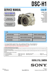
Photo: DSC-P43
Link
•
•
•
•
SPECIFICATIONS
BLOCK DIAGRAMS
PRINTED WIRING BOARDS
SERVICE NOTE
FRAME SCHEMATIC DIAGRAM
REPAIR PARTS LIST
DISASSEMBLY
SCHEMATIC DIAGRAMS
For ADJUSTMENTS (SECTION 6), refer to SERVICE MANUAL, ADJ (987674351.pdf).
For INSTRUCTION MANUAL, refer to SERVICE MANUAL, LEVEL 1 (987674341.pdf).
Reference No. search on printed wiring boards is available.
HELP: Sheet attachment positions and procedures of processing the flexible boards/harnesses are shown.
On the CH-146 and SY-101 boards
This service manual procides the information that is premised
the circuit board replacement service and not intended repair
inside the CH-146 and SY-101 boards.
Therefore, schematic diagram, printed wiring board and
electrical parts list of the CH-146 and SY-101 boards are not
shown.
The following pages are not shown.
Schematic diagram ............
Printed wiring board ...........
Mounted parts location .......
Electrical parts list ..............
Pages 4-9 to 4-26
Pages 4-39 to 4-42
Pages 4-50 and 5-51
Pages 5-7 and 5-10 to 5-14
The above-described information is shown in service
manual Level 3.
DIGITAL STILL CAMERA
DSC-P41/P43
SPECIFICATIONS
x Camera
[System]
Image device 6.85 mm (1/2.7 type) color
CCD
Primary color filter
Total pixels number of camera
Approx. 4 231 000 pixels
Effective pixels number of camera
Approx. 4 065 000 pixels
Lens
Fixed focal length lens
f=5.0 mm
(35 mm camera conversion: 33 mm)
F2.8
Exposure control
Automatic, Twilight, Twilight
portrait, Candle, Landscape, Beach,
Soft snap
White balance
Automatic, Daylight, Cloudy,
Fluorescent, Incandescent
File format (DCF compliant)
Still images: Exif Ver. 2.2, JPEG
compliant, DPOF compatible
Movies: MPEG1 compliant
(Monaural)
Recording medium
“Memory Stick”
Flash
Recommended distance (when ISO
sensitivity is set to Auto)
0.2 to 3.5 m (7 7/8 inches to
11 feet 5 7/8 inches)
[Input and output connectors]
A/V OUT (MONO) jack (Monaural) (DSC-P43
only)
Minijack
Video: 1 Vp-p, 75 Ω, unbalanced,
sync negative
Audio: 327 mV (at a 47 kΩ load)
Output impedance 2.2 kΩ
USB jack
mini-B
USB communication
Hi-Speed USB (USB 2.0 compliant)
[LCD screen]
LCD panel used
3.8 cm (1.5 type) TFT drive
Total number of dots
67 200 (280×240) dots
[Power, general]
Power
AA nickel hydride batteries (2)
2.4 V
AA alkaline batteries (2)
3.0 V
AC-LS5 AC Adaptor
(not supplied), 4.2 V
Power consumption (during shooting with LCD
screen on)
1.3 W
Operating temperature range
0° to +40°C (32° to +104°F)
(When using alkaline batteries: 5° to
+40°C (41° to +104°F))
Storage temperature range
–20° to +60°C (–4° to +140°F)
Dimensions 101.2 × 53.7 × 35.6 mm
(4 × 2 1/8 × 1 7/16 inches)
(W/H/D, protruding portions not
included)
Mass
Approx. 195 g (0.4 lb 6.9 oz) (two
batteries “Memory Stick,” wrist
strap, and so on included)
Microphone Electret condenser microphone
Speaker
Dynamic speaker
Exif Print
Compatible
PRINT Image Matching II
Compatible
PictBridge
Compatible
x BC-CS2A/CS2B Ni-MH battery
charger (supplied with the DSCP43)
Power requirements
AC 100 to 240V 50/60Hz
3W
Output voltage
AA : DC 1.4 V 400 mA × 2
AAA : DC 1.4 V 160 mA × 2
Operating temperature range
0° to +40°C (32° to +104°F)
Storage temperature range
–20° to +60°C (–4° to +140°F)
Dimensions 71 × 30 × 91 mm
(2 7/8 × 1 3/16 × 3 5/8 inches) (W/H/
D)
Mass
Approx. 90 g (3 oz)
x AC-LS5 AC Adaptor (not supplied)
Input rating
AC 100 to 240 V, 50/60 Hz
11 W, 0.16 to 0.09 A
Output rating DC 4.2 V, 1.5 A
Operating temperature range
0° to +40°C (32° to +104°F)
Storage temperature range
–20° to +60°C (–4° to +140°F)
Dimensions Approx. 48 × 29 × 81 mm (1 15/16 ×
1 3/16 × 3 1/4 inches) (W/H/D,
protruding portions not included)
Mass
Approx. 130 g (5 oz)
Accessories
• HR6 (size AA) Ni-MH batteries (2) (DSC-P43
only)
• R6 (size AA) alkaline batteries (2) (DSC-P41
only)
• Battery case (1)
• BC-CS2A/CS2B Ni-MH Battery charger (1)
(DSC-P43 only)
• Power cord (mains lead) (1) (DSC-P43 only)
• USB cable (1)
• A/V connecting cable (1) (DSC-P43 only)
• Wrist strap (1)
• “Memory Stick” (16MB) (1)
• CD-ROM (USB driver: SPVD-012) (1)
• Operating Instructions (1)
See page 5-15.
Design and specifications are subject to change
without notice.
—2—
DSC-P41/P43
SAFETY-RELATED COMPONENT WARNING!!
COMPONENTS IDENTIFIED BY MARK 0 OR DOTTED LINE WITH
MARK 0 ON THE SCHEMATIC DIAGRAMS AND IN THE PARTS
LIST ARE CRITICAL TO SAFE OPERATION. REPLACE THESE
COMPONENTS WITH SONY PARTS WHOSE PART NUMBERS
APPEAR AS SHOWN IN THIS MANUAL OR IN SUPPLEMENTS
PUBLISHED BY SONY.
ATTENTION AU COMPOSANT AYANT RAPPORT
À LA SÉCURITÉ!
LES COMPOSANTS IDENTIFÉS PAR UNE MARQUE 0 SUR LES
DIAGRAMMES SCHÉMATIQUES ET LA LISTE DES PIÈCES SONT
CRITIQUES POUR LA SÉCURITÉ DE FONCTIONNEMENT. NE
REMPLACER CES COMPOSANTS QUE PAR DES PIÈSES SONY
DONT LES NUMÉROS SONT DONNÉS DANS CE MANUEL OU
DANS LES SUPPÉMENTS PUBLIÉS PAR SONY.
SAFETY CHECK-OUT
After correcting the original service problem, perform the following
safety checks before releasing the set to the customer.
1.
2.
3.
4.
5.
6.
Check the area of your repair for unsoldered or poorly-soldered
connections. Check the entire board surface for solder splashes
and bridges.
Check the interboard wiring to ensure that no wires are
"pinched" or contact high-wattage resistors.
Look for unauthorized replacement parts, particularly
transistors, that were installed during a previous repair. Point
them out to the customer and recommend their replacement.
Look for parts which, through functioning, show obvious signs
of deterioration. Point them out to the customer and
recommend their replacement.
Check the B+ voltage to see it is at the values specified.
Flexible Circuit Board Repairing
• Keep the temperature of the soldering iron around 270˚C
during repairing.
• Do not touch the soldering iron on the same conductor of the
circuit board (within 3 times).
• Be careful not to apply force on the conductor when soldering
or unsoldering.
Unleaded solder
Boards requiring use of unleaded solder are printed with the leadfree mark (LF) indicating the solder contains no lead.
(Caution: Some printed circuit boards may not come printed with
the lead free mark due to their particular size.)
: LEAD FREE MARK
Unleaded solder has the following characteristics.
• Unleaded solder melts at a temperature about 40°C higher than
ordinary solder.
Ordinary soldering irons can be used but the iron tip has to be
applied to the solder joint for a slightly longer time.
Soldering irons using a temperature regulator should be set to
about 350°C.
Caution: The printed pattern (copper foil) may peel away if the
heated tip is applied for too long, so be careful!
• Strong viscosity
Unleaded solder is more viscous (sticky, less prone to flow) than
ordinary solder so use caution not to let solder bridges occur such
as on IC pins, etc.
• Usable with ordinary solder
It is best to use only unleaded solder but unleaded solder may
also be added to ordinary solder.
—3—
DSC-P41/P43
TABLE OF CONTENTS
Section
1.
Title
Page
SERVICE NOTE
1-1. Note for Repair ································································ 1-1
1-2. Discharging of the ST-098 Board’s Charging Capacitor
(C852) ·············································································· 1-1
1-3. Description on Self-diagnosis Display ···························· 1-2
2.
DISASSEMBLY
2-1.
2-2.
2-3.
2-4.
Flow Chart ······································································· 2-1
SY-101 Board Service Position ······································· 2-3
Circuit Boards Location ·················································· 2-5
Flexible Boards Location ················································ 2-5
3.
BLOCK DIAGRAMS
3-1.
3-2.
3-3.
3-4.
Overall Block Diagram (1/2) ··········································· 3-1
Overall Block Diagram (2/2) ··········································· 3-3
Power Block Diagram (1/2) ············································· 3-5
Power Block Diagram (2/2) ············································· 3-7
4.
PRINTED WIRING BOARDS AND
SCHEMATIC DIAGRAMS
4-1. Frame Schematic Diagram ·············································· 4-1
4-2. Schematic Diagrams ························································ 4-5
CD-501 (CCD IMAGER) ················································ 4-7
SW-420 (CONTROL SWITCH, LCD DRIVE) ············ 4-27
ST-098 (FLASH DRIVE) ·············································· 4-29
MS (FP-861 FLEXIBLE)
(MEMORY STICK CONNECTOR) ····························· 4-31
FP-860 FLEXIBLE (JACK) ·········································· 4-32
MICROPHONE UNIT (MA-001) ································· 4-33
CONTROL SWITCH BLOCK (RL51510) ··················· 4-34
4-3. Printed Wiring Boards ··················································· 4-35
CD-501 ·········································································· 4-37
SW-420 ·········································································· 4-43
ST-098 ··········································································· 4-45
MS (FP-861 FLEXIBLE) ·············································· 4-47
FP-860 FLEXIBLE ······················································· 4-48
4-4. Mounted Parts Location ················································ 4-49
5.
REPAIR PARTS LIST
5-1. Exploded Views ······························································· 5-2
5-1-1. Front Cabinet Block Section ··········································· 5-2
5-1-2. Lens Block Section ·························································· 5-3
5-1-3. BT Holder Block Section ················································ 5-4
5-1-4. Rear Cabinet Block Section ············································ 5-5
5-2. Electrical Parts List ························································· 5-6
—4—
DSC-P41/P43
SECTION 1
SERVICE NOTE
1-1. NOTE FOR REPAIR
Make sure that the flat cable and flexible board are not cracked of
bent at the terminal.
Do not insert the cable insufficiently nor crookedly.
When remove a connector, don’t pull at wire of connector.
It is possible that a wire is snapped.
When installing a connector, don’t press down at wire of connector.
It is possible that a wire is snapped.
Cut and remove the part of gilt
which comes off at the point.
(Be careful or some
pieces of gilt may be left inside)
1-2. DISCHARGING OF THE ST-098
BOARD’S CHARGING CAPACITOR
(C852)
Discharging the Capacitor
Short-circuit between the positive and the negative terminals of
charged capacitor with the short jig about 10 seconds.
The charging capacitor (C852) of the ST-098 board is charged up to
the maximum 300 V potential.
There is a danger of electric shock by this high voltage when the
capacitor is handled by hand. The electric shock is caused by the
charged voltage which is kept without discharging when the main
power of the unit is simply turned off. Therefore, the remaining
voltage must be discharged as described below.
Capacitor
R:1 kΩ/1 W
(Part code:
1-215-869-11)
Preparing the Short Jig
To preparing the short jig, a small clip is attached to each end of a
resistor of 1 kΩ /1 W (1-215-869-11).
Wrap insulating tape fully around the leads of the resistor to prevent
electrical shock.
1 kΩ/1 W
Wrap insulating tape.
1-1
ST
-09
58
DSC-P41/P43
1-3. DESCRIPTION ON SELF-DIAGNOSIS DISPLAY
Self-diagnosis display
• C: ss: ss
You can reverse the camera
malfunction yourself. (However,
contact your Sony dealer or local
authorized Sony service facility
when you cannot recover from the
camera malfunction.)
• E: ss: ss
Contact your Sony dealer or local
authorized Sony service facility.
Display Code
C:32:ss
Cause
Countermeasure
Caution Display During Error
Turn the power off and on again.
Trouble with hardware.
SYSTEM ERROR
Format the “Memory stick”.
Unformatted memory stick is inserted.
FORMAT ERROR
Insert a new “Memory Stick”.
Memory stick is broken.
MEMORY STICK ERROR
E:61:ss
Checking of lens drive circuit.
When failed in the focus and zoom
initialization.
E:91:ss
Checking of flash unit or replacement
of flash unit.
Abnormality when flash is being
charged.
Insert batteries correctly.
Batteries are not inserted correctly.
Turn the power off and on again.
Batteries were installed or removed when
using the AC adaptor.
C:13:ss
E:92:ss
1-2E
—
DSC-P41/P43
SECTION 2
DISASSEMBLY
HELP
2-1. FLOW CHART
The following flow chart shows the disassembly procedure.
5
Note: High-voltage cautions
3
6
3
4
1
3
Discharging the Capacitor
Short-circuit between the two
points with the short jig about 10
seconds.
5
4
2
1
2
1 Open the BT lid.
2 Screw (M1.7) x4
3 Open rear cabinet in the direction
of arrow.
4 Claw x1
5 Rear cabinet
Note: Flexible board is connected.
6 FP-859: CN201
Caution label
Tape (A) HELP
FP-853: CN702
FP-856: CN601
Lens block
Capacitor
R:1 kΩ/1 W
(Part code:
1-215-869-11)
2
21
1
2
3
4
5
ST
-09
58
1 Mic unit flexible: CN707
2 DC motor harness: CN602
3 Front cabinet
3
9
2
1
qs
4
8
2
qd
9
0
1
qa
7
1 Screw (M1.7) x2
2 Microphone unit
6
5
5
1
2
3
4
5
6
7
Control switch block
Control switch block flexible: CN706
FP-852: CN703
ST-098
Tapping screw x2
SP retainer plate
FP-860: CN751
8
9
0
qa
qs
qd
FP-861: CN705
Tapping screw x2
SY-101
BT harness: CN001
Tapping screw x1
MS
Refer to "5-1-3. BT HOLDER BLOCK SECTION" (Page 5-4)
for details.
2-1
2-2
DSC-P41/P43
2-2. SY-101 BOARD SERVICE POSITION
Rear cabinet block
Flush unit
ST-098 board
Control switch block
5
MS board
6
3
4
3
9
2
1
SY-101 board
qs
1
2
2
4
FP-860 flexible board
8
qd
9
0
3
Lens block
Color monitor
qa
7
DSC-P43 only
1
2
AC power
adaptor
6
5
AC IN
SW1
5
Microphone unit
SW2
2
3
Setting the "STILL" or "MOVIE" mode
5
Before turn on the power, you have to keep a switch (SW1)
pushed in order to maintain the "STILL" or "MOVIE" mode.
4
1
21
Setting the "VIEW" mode
Before turn on the power, you have to keep a switch (SW2)
pushed in order to maintain the "VIEW" mode.
2-3
2-4
DSC-P41/P43
2-3. CIRCUIT BOARDS LOCATION
SW-420
CH-146
(included in SY-101)
ST-098
CD-501
SY-101
(including CH-146)
MS (FP-861)
Board Name
Function
CD-501
CH-146
(included in SY-101)
MS (FP-861)
ST-098
SW-420
SY-101
(Including CH-146)
CCD IMAGER
CCD SIGNAL PROCESS
MEMORY STICK CONNECTOR
FLASH DRIVE
CONTROL SWITCH, LCD DRIVE
CAMERA MODULE, CAMERA DSP, LENS DRIVE, SH DSP,
FRONT CONTROL, AUDIO, DC/DC CONVERTER
2-4. FLEXIBLE BOARDS LOCATION
FP-852
Control switch block
FP-859
FP-853
FP-860
FP-856
Microphone unit
2-5E
DSC-P41/P43
HELP
Sheet attachment positions and procedures of processing the flexible boards/harnesses are shown.
Caution label
SY-101 board
Tape (A)
Tape (A)
HELP
DSC-P41/P43
3. BLOCK DIAGRAMS
Link
OVERALL BLOCK DIAGRAM (1/2)
POWER BLOCK DIAGRAM (1/2)
OVERALL BLOCK DIAGRAM (2/2)
POWER BLOCK DIAGRAM (2/2)
DSC-P41/P43
SECTION 3
BLOCK DIAGRAMS
SY-101 BOARD (1/2)
13
CN702
(1/2)
CCD OUT
32
CH-146 BOARD
8
6
12
IC801
FOCUS
MOTOR
M
15
ı
17
H
H1A, H2A
21
22
FOCUS
SENSOR
7
4
ı
1
V2, V4, V5A, V5B, V6
8
6
5
POWER
SAVE
10
9
19
8
10
13
RG, H1B, H2B 32
30
27
5
2
4
11
14
29
26
1
3
33
42
51 CCD SIGNAL
PROCESSOR,
37
TIMING
48 GENERATOR
22
19
ı
16
18
21
ı
24
9
12
ı
15
113 109
112 115
125
VHOLD
VST
VSUB
RANDOM
TRIG
5
20
Q802
45
46
48
133
25
24
1
Q803
49 105
66 101 120
99
IC101
37
23
21
20
V1A, V3A, V3B
22
ı
35
34
6
CCD
IMAGER
IRIS
METER
M
Q804
134 136 2 4
6 9 12 15
18 21 24
27 30 32
86
VSUB
CONT
3
17
19
20
7
10
11
10
17
20
15
16
39
20
19
21
7
11
19
35
36
135
IRIS HALL±
IRIS BIAS+
IRIS BIAS–
IRIS DRIVE–
IRIS DRIVE+
FOCUS A, A, B, B
126 127
128 129
3 123
TEMP OUT
LENS TEMP
SENSOR
40
41
42
84
47
LENS BARIA OUT A, B
M
1
HALL AD
HALL OFFSET
Q603
HALL GAIN
GAIN
CONTROL
IRIS DRIVE
Q601
IC606 (3/8)
2
D7
E8
SHUTTER
DRIVE
A6
B5
A4
B4
12
ı
15
FOCUS
MOTOR
DRIVE
IRIS CONT1, 2
C852
CHARGING
CAPACITOR
XE_H
T851
D852
5
CAMERA DSP
(2/8)
5
CLOCK
GENERATOR
(2/8)
EVR
(D/A CONVERTER)
(3/8)
3
1
2
6
7
27MHz
1
TRANS
DRIVE
3
3
L851
ST UNREG
XSTRB
PWRSAVE
2
4
XE_L
4
9
16
21
19
19
24
21
47
48
46
17
23
45
28
12
28
LED A
34
LED K
35
6
5
U4
AC20
HR EN2,
HR DIR2A,
HR DIR2B
B7
B8
C7
C8
P4
D7
AA11
L2
L3
M2
LENSV DIR
LENSV BRAKE
LENSV ENB
F2
STRB ON
AB20
J20
J22
AA21 AB22 AB23 AA22
Y19 Y21 Y20 W21
W20 V21 Y22 V20
W22 U21 U20 V22
T21 U22 T20 T22 R21
U23 R20 T23 P21 R22
R23 P20 N20 P22 N21
N23 M21 N22 M20 M23
L21 M22 L20 L22 K21
P1
2–6
16 32
34 35
CP, GPCK, GSRT,
SRT, STBYB, GRES,
OE, MCLK, HCNT
4
1
Q853
2
4
2
STB ON
2
3
OVERALL (2/2)
(PAGE 3-4)
1
OVERALL (2/2)
(PAGE 3-3)
DSC-P43
VIDEO AMP
(2/8)
V OUT
2
AU AIN
AU AOUT
XSYS RST
SYS V
IC501
MC CAM,
SH DSP,
FLASH
(4/8)
J1
K1
L1
M1
F1
H23
MC XCS IC 302REG
MC XCS IC 302SDRAM
MC D0 – D15
A17
C18
L21 L23 M24 K23
H22 J21 J22 F24
K21 H21 M23 K22
G21 L24 F23 E23
V22 V21 V23 R22 W22
U22 W21 T22 R23 N21
P22 P21 P23 R21 M22
T21 P24 U21 U23 N22
U24 N23 T24 M21 T23
MC A1 – A25
MC CKIO
A7
H1
AC12
AA9
AC16
A2
L22
AD20
F21
E21
C22
B16
B15
D16
XAU LINE MUTE
AU SEN
MELODY ENV
MELODY
USBPHY D±
PRELAMP AF CONT
SELF TIMER LED
TALLY LED
AE LOCK LED
LENSV OPEN SENS
LENSV CLOSE SENS
VER EXT CLK
HALL AD
HALL OFFSET
LENSV DIR
LENSV BRAKE
LENSV ENB
XSTRB PWR SAVE
STRB CHRG
XSTRB FULL
A6
D6
J2
G3
B5
B6
AB11
AD19
AC15
D703
(MS ACCESS)
Q708
LED
DRIVE
XACCESS LED
MC MS DIO,
MC MS BS, CN705
MC MS SCLK
4
3-2
MC MSDIO, MC MSBS,
MC MSSCLK
AB5
AB13
B13
D13
C13
AD11
D11
XMS IN
XAE LOCK ON
XSHTR ON
FR SI, FR SO, XFR SCK
FR INT
XCS MC
2
MEMORY
STICK
CN001
XMS IN
6
XSYS RST
SYS V
A : VIDEO SIGNAL
A : AUDIO SIGNAL
A : VIDEO/AUDIO SIGNAL
MS BOARD
(FP-861 FLEXIBLE BOARD)
2
8
A12
B12
C23
ST UNREG
Q702
AA18
D22
AB7
AD14
A11
B11
C11
D14
K2
AA8
CAM SO, XCAM SCK, XCAM RST
XSTRB PWR SAVE
D21
AD16
05
3-1
4
ı
7
21
ı
25
CN202
BL H
3
BL L
1
IC851
FLASH
CONTROL
COLOR
LCD
MONITOR
27
D901
BACKLIGHT
BL H
BL L
IC301
CAM F
XFE CS
XTG CS
LENS TEMP
Q703, 706
VCOM
25
LED K
LED A
BL LEV
VIDEO AMP ON
XPANEL TG CS
STRB CHRG
XSTRB FULL
STB FULL
16
LCD DRIVE
LCD901
SYS SO, XSYS SCK
2
1
3
24
CN203
VR
18
VG
20
VB
19
19
20
21
IC201
AC13
AB14
11
9
ı
12
43
42
AB21
XFC RST SENS
CN703
9
ı
12
17
18
E1
MSHUT ON
MSHUT EN
F7
F8
LENS COVER A2
B1
MOTOR
DRIVE
B3
7
CN851
4
+
TRIGGER
Q851, 852
23
22
HDO
PANEL V
XPANEL TG CS
ST-098 BOARD
FLASH
UNIT
40
39
38
SYS SI, SYS SO, XSYS SCK
CN602
M901
LENS COVER
MOTOR
IC304
IC605
HALL AMP,
HALL BIAS
CONTROL,
HALL GAIN
CONTROL
6
3
1
27
28
29
XSYS RST
IC302
PANEL UNIT
CN201
(1/2)
13
12
11
AQ0 – 10, BA0,1
CAM SO, XCAM SCK, XCAM RST
TG CLK
C1
D2
XFC RST SENS
SDRAM
(2/8)
IC602 IC604
(3/8)
IRIS
DRIVE
PANEL R
PANEL G
PANEL B
DQ0 – 31, DQM0 – 3
IC303
X301
54MHz
4
D6
C6
AC6
Y6
AC7
38 XFE CS, XTG CS
39
37
5
CA HD
CAM F
MCKTG
D1
C1
D2
BL LEV
132
124
CN601
AA10 AC10 Y10
AB10 AC9 AA8
AB9 Y8 Y9
AA7 AA9 Y7
AB8 AA6
CA AD00 – CA AD13
CN752
(1/2)
SYS SI, SYS SO, XSYS SCK
CN801
(1/2)
Q801
BUFFER
CAM SO, XCAM SCK, XCAM RST
IRIS
(SHUTTER)
SW-420 BOARD (1/2)
CP900
CAMERA
MODULE
(1/8)
CAM F
CD-501 BOARD (1/2)
LENS BLOCK
LENS
( ) : Number in parenthesis ( ) indicates the division number of schematic diagram where the component is located.
VER EXT CLK
3-1. OVERALL BLOCK DIAGRAM (1/2)
3. BLOCK DIAGRAMS
OVERALL (2/2)
(PAGE 3-3)
4
2
8
6
DSC-P41/P43
3. BLOCK DIAGRAMS
3-2. OVERALL BLOCK DIAGRAM (2/2)
( ) : Number in parenthesis ( ) indicates the division number of schematic diagram where the component is located.
SY-101 BOARD (2/2)
CN751
(1/2)
V OUT
V OUT
AU OUT
XAV JACK IN
FP-860 FLEXIBLE BOARD
(1/2)
31
33
29
DSC-P43
V OUT
J002
AU OUT
A/V OUT
(MONO)
XAV JACK IN
CN752
USBPHY D±
USBPHY D±
USB JACK IN
AU AIN
AU AOUT
OVERALL (1/2)
(PAGE 3-2)
H6
H7
1
26
24
22
2
3
USB DATA±
USB JACK IN
VCC
1
(USB)
F1
H2
H3
SYS SO, XSYS SCK
IC151
G4 AUDIO AMP
A2
(6/8)
H4
A4
XAU LINE MUTE
AU SEN
Q501
MODULATOR
MELODY ENV
BEEP
SP ±
SP ±
39
38
SP901
SPEAKER
C1
MELODY
TALLY LED
AE LOCK LED
PRELAMP AF CONT
SELF TIMER LED
LENSV OPEN SENS
LENSV CLOSE SENS
TALLY LED
AE LOCK LED
MICROPHONE UNIT (MA-001)
SW1
LENS COVER
OPEN DETECT
SW2
LENS COVER
CLOSE DETECT
LED
SELF TIMER/
AF ILLUMINATOR
Q402
USB JACK IN
C8
XAV JACK IN
LENCV
CLOSE SENS
LENCV OPEN SENS
PRELAMP AF ON
A3
Q401
XMS IN
CN707
B6
8
6
5
D1
D2
E1
FR SI, FR SO, XFR SCK
OVERALL (1/2)
(PAGE 3-2)
2
2
FR INT
XCS MC
XSYS RST
SYS V
D9
E2
B3
B9
XAE LOCK ON
XSHTR ON
CD-501 BOARD
(2/2)
D803
SELF TIMER/
RECORDING
IC401
FRONT
CONTROLLER
(5/8)
C1
D3
H1
E8
A9
H2
DDCON SO, DDCON SCK
XCS DDCON
SYS DD ON
BATT IN
FAST CHARGE
XRSTX
D801
(AE/AF LOCK)
XCHARGE LED
D802
(FLASH CHARGE)
36
CN702
(2/2)
2
3
Q707
LED
DRIVE
XCHARGE/XSTRB LED
1
VL 3V
36
D001
(POWER)
7
10
VLL 3V
BT001
LITHIUM
BATTERY
A10
5
ı
11
ACV UNREG
ST UNREG
L8
K8
12
K7
C7
D7
A7
E3
B7
ACV UNREG1
J001
DC IN
BATT/XEXT
Q009
CHG SW
E4
13
ı
19
ACV GND
1
2
BATT UNREG
3
4
BATT GND
CN001
BATT UNREG
CN752
(2/2)
J4
CN706
XSHTA ON
PLL
LOOP
FILTER
J2
J3
J6
H6
XRSTX
KEY AD0, 1
CN201
(2/2)
39
3
4
XRSTX
+
−
BT901
BATTERY
TERMINAL
KEY AD0, 1
S262
RESET
1
37
36
XAE LOCK ON
XPWR ON
S253
XPWR ON
XPOWER LED ON
XPOWER LED ON
S257
D-Zoom
T
B8
G6
KEY AD2
1
KEY AD2
39
S261
B2
J8
MODE DIAL0
2
MODE DIAL0
MOVIE
38
05
3-3
S251, 252,
254 – 256,
258 – 260
FUNCTION
KEY
W
S001
POWER
FP-860 FLEXIBLE BOARD
(2/2)
CN751
(2/2)
SW-420 BOARD (2/2)
J5
D7
3
ACV UNREG
DC/DC
CONTROL,
RESET
(7/8)
D8
B1
X401
32.768kHz
S002
(SHUTTER)
OVERALL (1/2)
(PAGE 3-2)
TALLY LED
AE LOCK LED
4
CONTROL SWITCH BLOCK
(RL51510)
IC001
3
BATT/XEXT
A7
CN801
(2/2)
XTALLY LED
38
XAE LOCK LED
37
LED A
LED K
BL LEV
G1
G2
B1
Q002
Q701
LED
DRIVE
MICROPHONE
MIC IN
PANEL 13.5V
BACK UP VCC
EVER 3.0V
A 3.1V
D 1.2V
D 2.8V
A 2.8V
CAM 15.5V
CAM –7.5V/–8.0V
A 5V
ST 5V
A7
3-4
STILL
VIEW
A : VIDEO SIGNAL
A : AUDIO SIGNAL
A : VIDEO/AUDIO SIGNAL
DSC-P41/P43
3. BLOCK DIAGRAMS
( ) : Number in parenthesis ( ) indicates the division number of schematic diagram where the component is located.
3-3. POWER BLOCK DIAGRAM (1/2)
SY-101 BOARD (1/2)
CN001
+
BT901
BATTERY
TERMINAL
BATT UNREG
CONTROL SWITCH BLOCK
(RL51510)
Q006, 007
F001
1
2
DC CONTROL
CN706
EVER 3.0V
F002
−
BATT GND
3
4
Q009
IC001
FP-860 FLEXIBLE BOARD
ACV UNREG1
J001
DC IN
BATT/XEXT
ACV GND
CN751
5
ı
11
MICROPHONE UNIT (MA-001)
DC/DC CONTROL, RESET
(7/8)
Q002
D001
(POWER)
9
D 1.2V
ACV UNREG
F003
F004
D015
CN707
L011, 002
L012
12
A 5V
D9 OUT8A
E9 OUT8B
B11 VCC8
LED
SELF TIMER/
AF ILLUMINATOR
4
E8 CPSW
C9 ODP SW
E4 CHG SW
13
ı
19
D1 VDCIN
Q005
H6 TLD
ST UNREG
MARK E5
BATT D4
D036
L014
D8 VBCK
36
D010, 012
G11 VCC1A
G10 VCC1B
G9 VCC1C
D 1.2V
BATT UNREG
ACV UNREG
F9 VCC2
B9 VLDO2
VCH1A
VCH1B
VCH1C (FB4)
VLDO1
A 2.8V
D 2.8V
L10
K9
L9
A11
EVER 3.0V
D 1.2V
VCH2 E11
OUT2 F10
L005
D011
L007
A10
J3
K1
J2
VLDO3
OUT3A
OUT3B
OUT3C
BACK UP VCC
BT001
LITHIUM
BATTERY
VLL 3V
VCH3A (FB3)
VCH3B
VCH3C (FB6)
VCH3S
A 5V
J1
H4
H3
H2
ST 5V
VCC GD H1
CAM 15.5V
VCH4 J6
D023
L008
OUT4 K6
VLDO4 C8
K5 VCC5
A
POWER 2
(PAGE 3-7)
A 3.1V
CAM –7.5V/–8.0V
VCH5 J5
D021
L009
OUT5 L5
PANEL 13.5V
VLDO5 B8
LED A
LED K
VCH6 G1
IC401
D025
FRONT CONTROLLER
(5/8)
L004
F005
OUT6 F1
ICH6 G2
BL THH
D035
G8 ACV SENS
H8 BATT SENS
F8 DD CON SENS
REF6 B1
BL LEV
VCH7 K3
A7 BATT/XEXT
C1
D3
H1
A9
H2
E8
DDCON SO,
DDCON SCK
XCS DDCON
BATT IN
FAST CHARGE
SYS DD ON
L8 DIN
K8 CLK
K7 LD
A7 CS
E3 FCHG
C7 SYSDDON
D7 USB PWR ON
SYS DD ON
05
3-5
3-6
DSC-P41/P43
3. BLOCK DIAGRAMS
3-4. POWER BLOCK DIAGRAM (2/2)
( ) : Number in parenthesis ( ) indicates the division number of schematic diagram where the component is located.
SY-101 BOARD (2/2)
ST-098 BOARD
CN703
ST UNREG
L701
Q703, 706
CN851
9
ı
12
ST 5V
ST UNREG
A 5V
1
T851
9
ı
12
FLASH
UNIT
IC851
1
FLASH
CONTROL
CP900
CAMERA MODULE
(1/8)
PANEL UNIT
SW-420 BOARD
CN752
CN201
30
PANEL 15V
A 2.8V
8
CN203
Q201, 202
L203
9
10
10
32
8
16
33
17
Q751
L751
4.9V
REG
SWD 5V
7
VGH
VDC
IC901
VDD
VDD
5
COLOR
LCD
MONITOR
VSH
3.3V
REG
(1/8)
54
55
71
4
L902
L903
XC.SAVE2 24
6
PANEL 13.5V/8.5V
L202
FB904
IC201
L201
PANEL 13.5V
CH-146 BOARD
LCD901
IC101
52
57
CCD SIGNAL
PROCESSOR,
TIMING
GENERATOR
56
LCD DRIVE
FB901
EXTDA 28
34
53
51
FB902
BL LEV
BL LEV
28
D901
BACKLIGHT
12
CN202
BL THH
LED A
LED K
A
36
34
35
4
6
5
6
3
1
SYS DD ON
49
BL THH
BL H
BL L
CAM 15.5V
A 5V
A 2.8V
POWER 1
(PAGE 3-6)
BL THH
BL H
BL L
SYS DD ON
CD-501 BOARD
Q904, 905
L900
CAM 15.5V
CAM 15.5V
CN702
10
CAM –7.5V/–8.0V
CAM –7.5V/–8.0V
CN801
12
CAM 15V
CAM –8.0V
FB802
30
IC801
FB801
CCD IMAGER
28
A 5V
A 5V
D803
SELF TIMER/
RECORDING
A 2.8V
A 2.8V
D 2.8V
D 2.8V
D 2.8V
1
EVER 3.0V
EVER 3.0V
CAM DD ON
STRB CHRG
A 5V
A 2.8V
FB306
CLOCK
GENERATOR
(2/8)
IC303
IC501
4
A 3.1V
A 3.1V
D 1.2V
D 1.2V
1.8V
REG
(4/8)
35
1
L501
SDA(O/D) AD18
Q704
CN705
CN001
VCC
9
9
MEMORY
STICK
MS PWR ON
L502
D 2.8V
LENS BLOCK
FB304
D 1.2V
A 2.8V
D802
(FLASH CHARGE)
MS BOARD
(FP-861 FLEXIBLE BOARD)
MC CAM,
SH DSP,
FLASH
(4/8)
IC502
SDRAM
(2/8)
EVER
D801
(AE/AF LOCK)
39
AC20 PU[6]
AD19 PU[0]
A 2.8V
D2.8V
IC304
5
D 2.8V
FB301
FB305
L301
IC302
CAMERA DSP
(2/8)
PI006 W2
L602
Q602
D 2.8V
CN601
8
FC SENS VCC
FOCUS
SENSOR
XLENZ RST LED
AU 2.8V
DSC-P43
IC606
L152
L153
IC151
IC301
AUDIO AMP
(6/8)
VIDEO AMP
(2/8)
A 5V
SHUTTER DRIVE,
FOCUS MOTOR DRIVE,
LENS COVER
MOTOR DRIVE
(3/8)
L604
EVR
(D/A CONVERTER)
(3/8)
L603
D 2.8V
05
3-7
IC605
3-8E
IC604
HALL AMP,
HALL BIAS CONTROL,
HALL GAIN CONTROL
(3/8)
IC602
IRIS DRIVE
(3/8)
DSC-P41/P43
4-2. SCHEMATIC DIAGRAMS
4-3. PRINTED WIRING BOARDS
SECTION 4
PRINTED WIRING BOARDS AND SCHEMATIC DIAGRAMS
4-1. FRAME SCHEMATIC DIAGRAM
1
2
3
5
4
6
7
8
11
10
9
12
13
14
15
16
17
A
CN801 39P
D_2.8V
XTALLY_LED
XAE_LOCK_LED
E
ST_UNREG
REG_GND
REG_GND
REG_GND
REG_GND
STB_FULL
XSTRB_PWRSAVE
STB_ON
A_5V
7
6
5
4
3
2
1
ST_UNREG
10
8
ST_UNREG
12P
ST_UNREG
11
CN851
12
12
11
10
9
8
7
6
5
4
3
2
1
ST_UNREG
ST_UNREG
ST_UNREG
REG_GND
REG_GND
REG_GND
REG_GND
STB_FULL
XSTRB_PWRSAVE
STB_ON
A_5V
12P
ST_UNREG
1
CN703
2
CN602
3
1
LENS_BARIA_OUT_B
XAE_LOCK_ON
2
LENS_BARIA_OUT_A
4
1
N.C
2
5
3
IRIS_DRIVE-
XSHTA_ON
4
IRIS_DRIVE+
6
5
IRIS_HALL-
N.C
6
IRIS_BIAS+
7
7
IRIS_BIAS-
REG_GND
8
IRIS_HALL+
8
9
XFC_RST_SENS
N.C
10
FC_SENS_VCC
9
11
REG_GND
XPWR_ON
12
NC
FP-852
FLEXIBLE
CN751 39P
CN702 39P
39
1
38
2
37
3
XCHARGE_LED
EVER
3
N.C
4
ACV_UNREG1
5
ACV_UNREG1
6
ACV_UNREG1
7
ACV_UNREG1
8
ACV_UNREG1
9
BATT/XEXT
XAE_LOCK_LED
4
2
N.C
ACV_UNREG1
XTALLY_LED
36
1
STATIC_GND
ACV_UNREG1
D_2.8V
XCHARGE_LED
STATIC_GND
FP-860
FLEXIBLE
BOARD
CN752
1
VCC
2
D-
3
D+
4
ID
5
GND
10
11
(USB)
12
ACV_GND
13
35
5
EVER
ACV_GND
14
GND
34
6
GND
ACV_GND
15
GND
33
7
GND
ACV_GND
16
CCD-OUT
32
8
CCD-OUT
ACV_GND
17
GND
31
9
GND
ACV_GND
18
CAM_15V
30
10
CAM_15V
ACV_GND
19
GND
29
11
GND
N.C
20
CAM_-8.0V
28
12
CAM_-8.0V
N.C
21
GND
27
13
GND
USB_JACK_IN
22
GND
26
14
GND
USB_GND
23
VHOLD
25
15
VHOLD
USB_DATA-
24
VST
24
16
VST
N.C
25
V1
23
17
V1
USB_DATA+
26
V2
22
18
V2
USB_GND
27
V3A
21
19
V3A
REG_GND
28
V3B
20
20
V3B
XAV_JACK_IN
29
V4
19
21
V4
REG_GND
30
V5A
18
22
V5A
V_OUT
31
V5B
17
23
V5B
AV_GND
32
V6
16
24
V6
AU_OUT
33
GND
15
25
GND
REG_GND
34
H2A
14
26
H2A
LI_GND
35
H2B
13
27
H2B
VLL_3V
36
GND
12
28
GND
REG_GND
37
H1A
11
29
H1A
SP-
38
H1B
10
30
H1B
SP+
39
GND
9
31
GND
RG
8
32
RG
A_5V
PRELAMP_AF_ON
LENCV_OPEN_SENS
REG-GND
LENCV_CLOSE_SENS
5
6
7
8
N.C
4
NIC_IN
MC_MSBS
2
CN705
VSS
1
3
KEY_AD2
1
2
MODE_DIAL0
2
8P
KEY_AD0
3
MIC_GND
KEY_AD1
4
CN707
REG_GND
5
1
PANEL_13.5V/8.5V
6
VSS
SWD_5V
7
10
A_2.8V
8
VCC
REG_GND
9
MC_MSCLK
REG_GND
10
MC_MSD3
PANEL_B
11
9
PANEL_G
12
8
PANEL_R
13
7
REG_GND
14
XMS_IN
REG_GND
15
MC_MSD2
SYS_SI
16
MC_MSDIO
XPANEL_TG_CS
17
6
REG_GND
18
5
XSYS_SCK
19
4
REG_GND
MC_MSD1
SYS_SO
20
3
PANEL_V
21
10P
HDO
22
REG_GND
26
23
REG_GND
27
XSYS_RST
BL_LEV
28
REG_GND
REG_GND
29
24
PANEL_15V
30
25
REG_GND
31
VSUB
REG_GND
39
32
1
REG_GND
VSUB
33
GND
BL_H
VSUB_CONT
38
34
GND
37
2
BL_L
36
3
35
4
GND
BL_THH
GND
VSUB_CONT
36
RANDOM_TRIG
BL_THL
POWER_SAVE
35
37
GND
34
5
REG_GND
33
6
38
7
39P
I
GND
POWER_SAVE
RANDOM_TRIG
CN001 4P
XRSTX
H
CN752
CD-501
BOARD
SY-101 BOARD
CH-146
BOARD
39
F
FP-853 FLEXIBLE
CP900
LENS
BLOCK
G
10
13
TEMP_OUT
D
CN706 10P
14
FOCUS_B
2P
15
FOCUS_A
15P
FOCUS_B-
CN601
FOCUS_A-
OVF
N.C
FP-856 FLEXIBLE
C
EVER_3.0V
CONTROL
SWITCH
BLOCK
(RL51510)
M
XPOWER_LED_ON
B
9
ST-098
BOARD
M901
LENS COVER
MOTOR
BATT_GND
4
BATT_GND
3
BATT_UNREG
2
BATT_UNREG
1
BT901
BATTERY
TERMINAL
FP-859 FLEXIBLE
VSS
VCC
SCLK
DATA3
INT
DATA2
DIO
DATA1
BS
VSS
9
8
7
6
5
4
3
2
1
CN001
10
17
18
19
20
21
22
23
24
25
26
27
28
29
30
31
32
33
34
35
36
37
38
39
HDO
SYS_SO
REG_GND
XSYS_SCK
REG_GND
XPANEL_TG_CS
SYS_SI
REG_GND
REG_GND
PANEL_R
PANEL_G
PANEL_B
REG_GND
REG_GND
A_2.8V
SWD_5V
PANEL_13.5V/8.5V
REG_GND
KEY_AD1
KEY_AD0
MODE_DIAL0
KEY_AD2
16
PANEL_V
15
REG_GND
14
REG_GND
XSYS_RST
13
REG_GND
MEMORY STICK
N.C.
BL_THH
6
N
5
VCOM
BL_THL
27
4
VBC
BL_H
26
12
MEMORY
STICK
3
STBYB
MICROPHONE UNIT
(MA-001)
10
1
11
N.C.
SRT
25
12
SW-420
BOARD
OE
24
11
MCLK
23
BL_LEV
HCNT
22
REG_GND
VG
21
9
VB
20
10
19
REG_GND
VR
PANEL_15V
VSH (5V)
18
8
VDD (3V)
17
REG_GND
16
7
VSS
REG_GND
VGL
15
6
C2
14
BL_H
C1
13
5
VSS
12
BL_L
VDC (15V)
11
4
VGH (15V)
10
BL_THH
VDD (3V)
9
3
CP
8
BL_THL
GRES
7
2
GPCK
6
REG_GND
GSRT
5
2
M
NC
4
BL_L
D901
BACK
LIGHT
NC
3
1
L
2
MS
FP-861
FLEXIBLE
BOARD
6P
K
NC
CN202
LCD901
1.5INCH
COLOR
LCD
MONITOR
1
1
CN203 27P
CN201 39P
PANEL UNIT
XRSTX
J
05
4-1
4-2
FRAME
DSC-P41/P43
4-2. SCHEMATIC DIAGRAMS
Link
CD-501 BOARD (CCD IMAGER)
SW-420 BOARD
(CONTROL SWITCH, LCD DRIVE)
ST-098 BOARD (FLASH DRIVE)
MS BOARD (FP-861 FLEXIBLE BOARD)
(MEMORY STICK CONNECTOR)
COMMON NOTE FOR SCHEMATIC DIAGRAMS
FP-860 FLEXIBLE BOARD (JACK)
MICROPHONE UNIT (MA-001)
CONTROL SWITCH BLOCK (RL51510)
DSC-P41/P43
4-2. SCHEMATIC DIAGRAMS
4-2. SCHEMATIC DIAGRAMS
THIS NOTE IS COMMON FOR SCHEMATIC DIAGRAMS
(In addition to this, the necessary note is printed in each block)
(For schematic diagrams)
• All capacitors are in µF unless otherwise noted. pF : µ
Link
µF. 50 V or less are not indicated except for electrolytics
and tantalums.
• Chip resistors are 1/10 W unless otherwise noted.
kΩ=1000 Ω, MΩ=1000 kΩ.
• Caution when replacing chip parts.
New parts must be attached after removal of chip.
Be careful not to heat the minus side of tantalum
capacitor, Because it is damaged by the heat.
• Some chip part will be indicated as follows.
Example
C541
L452
22U
10UH
TA A
2520
1. Connection
Pattern box
L
Front of the lens
Kinds of capacitor
L = About 23 cm (PTB-450)
L = About 11 cm (PTB-1450)
Case Size
External dimensions (mm)
• Constants of resistors, capacitors, ICs and etc with XX
indicate that they are not used.
In such cases, the unused circuits may be indicated.
• Parts with ★ differ according to the model/destination.
Refer to the mount table for each function.
• All variable and adjustable resistors have characteristic
curve B, unless otherwise noted.
• Signal name
XEDIT → EDIT
PB/XREC → PB/REC
• 2: non flammable resistor
• 5: fusible resistor
• C: panel designation
• A: B+ Line
• B: B– Line
• J : IN/OUT direction of (+,–) B LINE.
• C: adjustment for repair.
• A: VIDEO SIGNAL (ANALOG)
• A: AUDIO SIGNAL (ANALOG)
• A: VIDEO/AUDIO SIGNAL
• A: VIDEO/AUDIO/SERVO SIGNAL
• A: SERVO SIGNAL
• Circled numbers refer to waveforms.
(Measuring conditions voltage and waveform)
• Voltages and waveforms are measured between the
measurement points and ground when camera shoots
color bar chart of pattern box. They are reference values
and reference waveforms.
(VOM of DC 10 MΩ input impedance is used)
• Voltage values change depending upon input
impedance of VOM used.)
Note :
2. Adjust the distance so that the display of Fig. a can be
obtain.
C
C=D
D
B
A=B/2
B
A
A
Fig.a (Picture on LCD display)
or
(Picture on under scan monitor TV)
: DSC-P43
When indicating parts by reference number, please
include the board name.
Note :
The components identified by mark 0 or
dotted line with mark 0 are critical for safety.
Replace only with part number specified.
4-5
Les composants identifiés par une marque
0 sont critiques pour la sécurité.
Ne les remplacer que par une pièce portant
le numéro spécifie.
DSC-P41/P43
4-2. SCHEMATIC DIAGRAMS
CD-501 BOARD
For Schematic Diagram
• Refer to page 4-37 for printed wiring board.
1
2
3
4
6
8
7
9
10
11
12
Note: Voltage and Waveform of mounted IC801 on CD-501
board can not be measured because this is mounted
by the side of the lens.
CD-501 BOARD
A
5
FB801
CCD IMAGER (CCD BLOCK)
XX MARK:NO MOUNT
NO MARK:REC/PB MODE
R:REC MODE
P:PB MODE
B
E
SY-101
(1/8)
CN702
THROUGH THE
FP-853 FLEXIBLE
PAGE 4-12
of LEVEL3
F
12
H2B
13
H2A
14
GND
15
V6
16
V5B
17
V5A
18
V4
19
V3B
20
V3A
21
V2
22
V1
23
VST
24
VHOLD
25
GND
26
GND
27
CAM_-8.0V
28
GND
29
CAM_15V
30
C802
XX
R801
3300
C801
10p
Q801
2SC39320S2S0
BUFFER
FB802
R14.9/P0
G
31
32
GND
33
GND
34
EVER
35
XCHARG_LED
36
XAE_LOCK_LED
37
XTALLY_LED
38
D_2.8V
39
V4
V 5A
V 5B
V6
V 3B
C804
0.1u 16V
R803
0
R809
180k
Q803
DTC144EMT2L
SWITCH
D802
SML-310YTT86
(FLASH CHARGE)
R814 82
D801
SML-510MWT86S
(AE/AF LOCK)
R804
1M
C806
XX
50V
R805
Q802
DTC144EMT2L
SWITCH
0
R13.6
/P0
C807
0.1u
16V
SIGNAL PATH
Precautions for Replacement of CCD Imager
• The CD-501 board mounted as a repair part is not equipped
with a CCD imager.
When replacing this board, remove the CCD imager from the
old one and mount it onto the new one.
• If the CCD imager has been replaced, carry out all the
adjustments for the camera section.
• As the CCD imager may be damaged by static electricity from
its structure, handle it carefully like for the MOS IC.
In addition, ensure that the receiver is not covered with dusts
nor exposed to strong light.
R815
82
D803
SML-310LTT86
(SELE TIMER/RECORDING)
H
C810
10u
16V
C803
0.1u
16V
R13.1/P0
GND
C805
0.1u
16V
R11.7
/P0
Note: IC801 is not included
in CD-501 complete board.
0
CCD-OUT
13 14 15 16 17 18 19 20 21 22 23 24
R10.9
/P0
C809
0.1u
16V
R802
0
CCD IMAGER
IC801
ICX488DQF-13
VL
GND
1
GND
11
2
H 2A
H1A
3
H 1A
10
4
IC801
C sub
9
H1B
V2
8
5
V 3A
RG
GND
6
SUB
7
V1
GND
7
GND
6
8
V ST
5
POWER_SAVE
9
H 2B
4
RANDOM_TRIG
12 11 10
H 1B
3
GND
C808
XX
16V
GND
VSUB_CONT
SWITCH
0
V HOLD
2
GND
1
GND
R806
2200
R4.5/P0
RG
D
VSUB
R807
1k
VDD
C
Q804
DTC144EMT2L
39P
V OUT
CN801
VIDEO
SIGNAL
R816
820
Y/CHROMA
REC
05
4-7
4-8
CD-501
Schematic diagrams of the CH-146 and SY-101 boards are not shown.
Pages from 4-9 to 4-26 are not shown.
DSC-P41/P43
4-2. SCHEMATIC DIAGRAMS
SW-420 BOARD
For Schematic Diagram
• Refer to page 4-43 for printed wiring board.
1
2
3
4
5
6
8
7
9
10
12
11
13
14
16
15
17
SW-420 BOARD
A
CONTROL SWITCH, LCD DRIVE (PD BLOCK, SW BLOCK)
XX MARK:NO MOUNT
NO MARK:REC/PB MODE
L203 10uH
15
L202
10uH
15
C219
XX
R211
470k
0
CN201 39P
KEY_AD2
R212
0
MODE_DIAL0
1
Q202
SSM3J09FU(TE85L)
SWITCH
IC201 ek REC/PB
KEY_AD0
9
KEY_AD1
11
PANEL_15V
10
R216
560
±0.5%
R217
560
±0.5%
XVD
2.9
C205
0.1u
10V
2.7
XHD
9
REG_GND
8
REG_GND
7
BL_H
6
XCS
2.9
45
F
44
2.8
BL_H
BL_L
5
BL_THH
4
BL_THL
3
2.9
XSCK
46
BL_L
BL_THH
0
47
SI
BL_THL
SO
XRSTX
1
4
G
VCOM
OE
6.8
13.5
COM OUT
VCC3
GIN
VCC2
H
RIN
VB
SCANEN
VG
IC201
VR
LCD DRIVE
IC201
CM7103L43-T4
GND2
XVD
HD
VCC1
GND1
3
XCS
IC201 r; REC/PB
GRES
XSCK
STBYB
480 mVp-p
SI
N.C.
SO
VDD1
H
IC201 rs REC/PB
2.9 Vp-p
2
3
1.4
1
4
5
6
7
8
9
24
23
22
XLED
COM DA
21
1.4
2.8
400 mVp-p
N.C
2
48
REG_GND
2.7
XC.SAVE2
20
1.8
11
STBYB
24
SRT
23
OE
22
MCLK
21
HCNT
20
VG
19
VB
18
VR
17
VSH (5V)
16
VDD (3V)
15
VSS
14
VGL
13
C2
12
C1
11
VSS
10
VDC (15V)
9
VGH (15V)
8
VDD (3V)
7
CP
6
GRES
5
GPCK
4
GSRT
3
NC
2
NC
1
NC
VG
VB
2.9
2.9
R206
10k
1.3
D201
XX
JL201
VR
Q201
DTC144EMT2L
SWITCH
4.9
C215
XX 10V
2.5
D202
VB
2.5
R214
470k
VG
C217
2.2u
16V
VR
2.5
RB481YT2R
2
1
3
4
C216
0.1u
16V
C218
1u 16V
LCD901
1.5INCH
COLOR
LCD
MONITOR
CP
GRES
2.6
GRES
GPCK
GSRT
2.9
8
IC201 wa REC/PB
C212
0.1u
10V
10
25
PANEL UNIT
MCLK
0
19
12
0.01u
VBC
OE
18
BL_LEV
REG_GND
C204
VCOM
26
HCNT
IC201 el REC/PB
BIN
27P
27
SRT
17
13
0.01u
25
150k
STBYB
C214
1u
10V
C213
6.8u
16V
16
14
REG_GND
C203
1.8
26
Filter
REG_GND
1.8
R210
Filter2
15
0.01u
C202
39
16
REG_GND
R215
560
±0.5%
2.9
VDD2
27
CN203
JL202
VCOM
3.3 Vp-p
CN202
6P
BL_THH
2H
12
1.1
17
XSYS_RST
REG_GND
38
XHD
HDO
E
37
XVD
28
POCB
18
2
29
OP_IN
PANEL_V
SI
30
2.9
19
31
1.3
20
SYS_SO
32
STBYB
REG_GND
33
EXTDA
XSCK
34
1.3
21
35
HCNT
XSYS_SCK
40
PAGE 4-25
of LEVEL3
22
41
CN752
THROUGH THE
FP-859 FLEXIBLE
23
REG_GND
42
SY-101
(8/8)
XPANEL_TG_CS
43
D
36
VSS2
XCS
BLDET
SO
C211
0.1u
16V
2.8
24
C208
4.7u
16V
OE
25
SYS_SI
C206
2.2u
25V
PWM
REG_GND
C201
47u
6.3V
2.9
26
CLR
27
SRT
28
PANEL_R
REG_GND
GSRT
29
0.1
PANEL_B
PANEL_G
2H
GPCK
30
0
REG_GND
L201
47uH
HCNT
31
MCLK
32
1.4
A_2.8V
REG_GND
5.8 Vp-p
H
1.4
33
MCLK
34
0.1
35
SWD_5V
CP
C
REG_GND
PANEL_13.5V/8.5V
IC201 wg REC/PB
370 mVp-p
N.C
36
OP_OUT
37
1.4
KEY_AD0
KEY_AD1
15
38
14
39
MODE_DIAL0
13
KEY_AD2
VSS1
B
6
BL_THH
5
N.C.
4
BL_THL
3
BL_H
2
N.C.
1
BL_L
D901
BACKLIGHT
BL_THL
BL_H
V
6
R201
1k
7
IC201 ql REC/PB
IC201 w; REC/PB
BL_L
3.0 Vp-p
H
5
IC201 rd REC/PB
R213 XX
2.9 Vp-p
C207
2200p
50V
C210
560p
R203
68k
C209
0.1u
2H
3.0 Vp-p
2H
R205
10k
STBYB
SRT
GSRT
GPCK
CP
I
R204
100k
R202 XX
H
R256 1500
MOVIE
S261
(MODE SWITCH)
STILL
S256
VIEW
S251
S254
J
S262
RESET
R260
1k
(SPOT METERING)
S258
S260
MENU
IMAGE SIZE/
DELETE
(FLASH)
1Pin
R262
1200
R259 3300
R253
1200
(SET)
R252
1500
R251
3300
R254
S252
S255
(REVIEW)
(SELF TIMER)
R257
1500
R258
3300
1200
KEY_AD1
SIGNAL PATH
S259
KEY_AD0
LCD STATUS
LCD ON/OFF
MODE_DIAL0
VIDEO SIGNAL
R255
1200
KEY_AD2
CHROMA
K
REC
D251
MAZW068H0LS0
D252
MAZW068H0LS0
R261
XX
LND251
STATIC_GND
S253
W
D-Zoom
S257
T
PB
D253
MA2S111-(K8).SO
05
The components identified by mark 0 or dotted
line with mark 0 are critical for safety.
Replace only with part number specified.
4-27
4-28
Les composants identifiés par une marque 0 sont
critiques pour la sécurité. Ne les remplacer que
par une piéce portant le numéro spécifié.
SW-420
DSC-P41/P43
4-2. SCHEMATIC DIAGRAMS
ST-098 BOARD
For Schematic Diagram
• Refer to page 4-45 for printed wiring board.
1
3
2
5
4
6
8
7
9
10
ST-098 BOARD
A
FLASH DRIVE (ST BLOCK)
D852
HAU160C030STP
T851
XX MARK:NO MOUNT
NO MARK:REC/PB MODE
4
5
LND851
P
1
XE_H
R851
2200
0
B
3
R855
150
R853
1800
C851
0.22u
S
F
R859
1M
2
R856
4700
0
Q851
CPH3235-S-TL-E
TRANS DRIVE
LND853
0
0
1
3
0
C
2
FLASH
UNIT
Q852
RTF025N03TL
TRANS DRIVE
C852
135uF
310V
CHARGING
CAPACITOR
C853
0.047u
LND852
XE_L
R852
100k
274
R854
10k
CN851
SY-101
(8/8)
C854
0.1u
12P
ST_UNREG
12
ST_UNREG
11
ST_UNREG
10
ST_UNREG
9
REG_GND
8
REG_GND
7
REG_GND
6
1
2
3
4
8
7
6
5
Q853
CY25BAJ-8F-T23
FLASH DRIVE
D851
MA111-(K8).S0
D
L851
TRIGGER
R857
47
0
R858
1M
PAGE 4-26
of LEVEL3
REG_GND
5
STB_FULL
4
XSTRB_PWRSAVE
3
STB_ON
2
A_5V
1
5
IN
VDD
5
IC851
0
4
1
OUT
0
3
E
NC
GND
2
CN703
THROUGH THE
FP-852 FLEXIBLE
FLASH CONTROL
IC851
TND721MH5-S-TL-E
F
05
The components identified by mark 0 or dotted
line with mark 0 are critical for safety.
Replace only with part number specified.
ST-098
4-29
4-30
Les composants identifiés par une marque 0 sont
critiques pour la sécurité. Ne les remplacer que
par une piéce portant le numéro spécifié.
DSC-P41/P43
4-2. SCHEMATIC DIAGRAMS
For Schematic Diagram
• Refer to page 4-47 for printed wiring board.
1
2
FP-860 FLEXIBLE BOARD
For Schematic Diagram
• Refer to page 4-48 for printed wiring board.
3
4
5
6
1
7
MS BOARD (FP-861 FLEXIBLE BOARD)
A
MS BOARD
3
4
6
5
FP-860 FLEXIBLE BOARD
A
MEMORY STICK CONNECTOR
2
7
Note: FP-860 flexible board is replaced as block,
but BT001 and SP901 are not included in FP-860 flexible board.
JACK
B
VSS
9
VCC
9
VCC
8
MC_MSCLK
8
SCLK
7
MC_MSD3
7
DATA3
6
XMS_IN
6
INT
MEMORY
STICK
B
MEMORY STICK
5
MC_MSD2
5
DATA2
4
MC_MSDIO
4
DIO
3
MC_MSD1
3
DATA1
2
MC_MSBS
2
BS
1
VSS
1
VSS
STATIC_GND
1
STATIC_GND
2
N.C
3
N.C
4
STATIC_GND
C001
0.1u
4
1
ACV_UNREG1 5
1
CN705
PAGE 4-25
of LEVEL3
10
10
SY-101
(8/8)
VSS
12
CN001
10
J001
3
11
ACV_UNREG1 6
DC IN
2
ACV_UNREG1 7
5
ACV_UNREG1 8
ACV_UNREG1 9
ACV_UNREG1 10
C
C
ACV_UNREG1 11
STATIC_GND
SIGNAL PATH
VIDEO SIGNAL
Y/CHROMA
D
AUDIO
SIGNAL
D
REC
05
E
12
ACV_GND
13
ACV_GND
14
ACV_GND
15
ACV_GND
16
ACV_GND
17
SY-101
(8/8)
ACV_GND
18
CN751
ACV_GND
19
N.C
20
N.C
21
PAGE 4-26
of LEVEL3
PB
BATT/XEXT
CN752
USB_JACK_IN 22
1
VCC
USB_GND
2
D-
23
USB_DATA-
24
3
D+
N.C
25
4
ID
USB_DATA+
26
5
GND
USB_GND
27
REG_GND
28
6
XAV_JACK_IN 29
F
G
REG_GND
30
V_OUT
31
AV_GND
32
AU_OUT
33
REG_GND
34
LI_GND
35
VLL_3V
36
(USB)
7
DSC-P43
1
2
3
4
J002
A/V OUT
(MONO)
BT001
LITHIUM
BATTERY
REG_GND
37
SP-
38
SP-
SP+
39
SP+
SP901
SPEAKER
SIGNAL PATH
VIDEO SIGNAL
Y/CHROMA
AUDIO
SIGNAL
PB
H
05
The components identified by mark 0 or dotted
line with mark 0 are critical for safety.
Replace only with part number specified.
4-31
4-32
Les composants identifiés par une marque 0 sont
critiques pour la sécurité. Ne les remplacer que
par une piéce portant le numéro spécifié.
MS (FP-861), FP-860
DSC-P41/P43
4-2. SCHEMATIC DIAGRAMS
1
2
3
MICROPHONE UNIT (MA-001)
A
1
4
2
3
4
CONTROL SWITCH BLOCK
(RL51510)
A
MICROPHONE UNIT (MA-001) is replaced as block,
so that PRINTED WIRING BOARD is omitted.
CONTROL SWITCH BLOCK (RL51510) is replaced as block,
so that PRINTED WIRING BOARD is omitted.
D001
(POWER)
SW1
LENS COVER
OPEN DETECT
B
SW2
LENS COVER
CLOSE DETECT
B
8 LENCV_CLOSE_SENS
7
MICROPHONE
C
10 XPOWER_LED_ON
REG_GND
9
6 LENCV_OPEN_SENS
LED
SELF TIMER/
AF ILLUMINATOR
5
PRELAMP_AF_ON
4
A_5V
3
N.C
2
MIC_IN
1
MIC_GND
SY-101 (6/8)
8
N.C
SY-101 (5/8)
7
XPWR_ON
CN706
PAGE 4-20
of LEVEL3
6
N.C
5
REG_GND
CN707
PAGE 4-21
of LEVEL3
C
SIGNAL PATH
S001
EVER_3.0V
4
N.C
3
XSHTA_ON
2
N.C
1
XAE_LOCK_ON
POWER
(2nd)
(1st)
AUDIO
SIGNAL
D
REC
05
MA-001, RL51510
S002
(SHUTTER)
D
05
4-33
4-34
DSC-P41/P43
4-3. PRINTED WIRING BOARDS
Link
CD-501 BOARD
MS BOARD (FP-861 FLEXIBLE BOARD)
SW-420 BOARD
FP-860 FLEXIBLE BOARD
ST-098 BOARD
COMMON NOTE FOR PRINTED WIRING BOARDS
MOUNTED PARTS LOCATION
CIRCUIT BOARDS LOCATION
Board Name
Function
CD-501
SW-420
ST-098
MS (FP-861)
CCD IMAGER
CONTROL SWITCH, LCD DRIVE
FLASH DRIVE
MEMORY STICK CONNECTOR
FLEXIBLE BOARDS LOCATION
DSC-P41/P43
4-3. PRINTED WIRING BOARDS
4-3. PRINTED WIRING BOARDS
THIS NOTE IS COMMON FOR PRINTED WIRING BOARDS
•
•
•
•
•
•
• Chip parts.
Transistor
: Uses unleaded solder.
: Circuit board
: Flexible board
Pattern from the side which enables seeing.
: pattern of the rear side
(The other layers’ patterns are not indicated)
Through hole is omitted.
Circled numbers refer to waveforms.
There are a few cases that the part printed on diagram
isn’t mounted in this model.
C: panel designation
Board Name
Parts Location
CD-501
4-49
B
Diode
6 5 4 4 5 6 5
C
E
4 4
1 2 3 3 2 1 1 2 3 3 2 1
1
3
3
1 23
2
1 2
1 2
1 3
4 3
4
1
2 3
4
4
3
3
4
5 4 3 3 4 5 2
1 2
1
4
3 2
1 1
2
2
1
3
4 6 5 4 4 5 6
2
1 1 2 3 3 2 1
2 2
Pattern
Total Number of Layers
Layers Not Indicated
4 layers
2 and 3 layers
SW-420
4-52
4 layers
2 and 3 layers
ST-098
4-52
4 layers
2 and 3 layers
MS
–
1 layer
–
4-35
3
5
1 6 54
DSC-P41/P43
4-2. SCHEMATIC DIAGRAMS
4-3. PRINTED WIRING BOARDS
MOUNTED PARTS LOCATION
CD-501
Note for Printed Wiring Board (See page 4-35).
: Uses unleaded solder.
CD-501 BOARD (SIDE A)
CD-501 BOARD (SIDE B)
K
D803
SELF TIMER/
RECORDING
A
D803
A
Note: IC801 is not included in
CD-501 complete board.
A
D801
(AE/AF LOCK)
K
D801
D802
(FLASH CHARGE)
A
A
K
R815
R806
R816
R814
38
C808
39
R807
BCE
B
B
1
CN801
12
IC801
24
2
13
C
C806
R804
C810
R809
Q803 E C B
R805
R802
C805
B
ECB
C807
FB801
C804
C809
C803
E
C802
C
R801
Q802
Q801
B
C801
R803
+
C
1
Q804
D802
FB802
D
1-860-28705
1
2
4-37
11
11
1-860-287-
3
05
3
2
D
1
4-38
CD-501
Printed wiring boards of the CH-146 and SY-101 boards are not shown.
Pages from 4-39 to 4-42 are not shown.
DSC-P41/P43
4-2. SCHEMATIC DIAGRAMS
4-3. PRINTED WIRING BOARDS
MOUNTED PARTS LOCATION
SW-420
Note for Printed Wiring Board (See page 4-35).
: Uses unleaded solder.
SW-420 BOARD (SIDE A)
SW-420 BOARD (SIDE B)
S261
VIEW
STILL
MOVIE
S257
S253
S259
A
A
S261
W
C215
S251
C212
8 7 6
D201
C207
R251
R262
LCD STATUS/
LCD ON/OFF
JL201
T
D-Zoom
R252
R210
R261
R201
S259
12
24
S258
1
S260
D
G
S
LND251
C210
S262
1-860-286-
SW-420
1
2
3
4-43
C209
S262
11
4
05
4
3
2
4-44
R255
D253
1-860-286-
RESET
KAK
C214
R260
Q202
2
L201
C211
KAK
(SELF TIMER)
+ C201 A
D251 D252
CN202
S258
MENU
A C206 +
L202
C208
6
1
CN201
05
1
36
IC201
25
R259
R253
IMAGE SIZE/
DELETE
S255
+ C213 A
C204
C205
S260
(SET)
S255
C
R257
C203
L203
R214
C202
S254
S252
(REVIEW)
38
1
R217
1
C218
39
R213
R211
R216
B
R202
4 5
R203
S256
R204
48
S254
2
R215
R205
2
C219
R258
R254
S252
9
3
R212
C217
C216
R256
37
C
B E
CN203
B
(SPOT METERING)
Q201
3 4
2 1
JL202
S256
D202
26
27
(FLASH)
13
R206
S251
1
11
C
DSC-P41/P43
4-2. SCHEMATIC DIAGRAMS
4-3. PRINTED WIRING BOARDS
MOUNTED PARTS LOCATION
ST-098
Note for Printed Wiring Board (See page 4-35).
: Uses unleaded solder.
ST-098 BOARD (SIDE A)
4
R854
LND851
LND852
L851
1
G
R852
3
C854
5
R856
1
S
2
8
12
D
Q852
A
CN851
R853
R855
LND853
Q853
R851
C851
1
A
A
K
4
D852
R859
1
05
IC851
1
5
3
FLASH UNIT
2
3
2
3
4
1-860-288- 11
4
C852
5
4
2
R858
R857
Q851
C
B
1
4-45
E
D851
1
05
T851
3
2
C853
A
1
ST-098 BOARD (SIDE B)
1-860-288- 11
4-46
ST-098
DSC-P41/P43
4-2. SCHEMATIC DIAGRAMS
4-3. PRINTED WIRING BOARDS
MS (FP-861 FLEXIBLE)
FP-860 FLEXIBLE
Note for Printed Wiring Board (See page 4-35).
Note for Printed Wiring Board (See page 4-35).
: Uses unleaded solder.
: Uses unleaded solder.
MS BOARD
(FP-861 FLEXIBLE BOARD)
FP-860 FLEXIBLE BOARD
1
10
C0
01
1
4
1
J001
2
DC IN
5
3
6
1
39
2
3
SP+
CN752
4
SP901
(USB)
5
SP–
7
DSC-P43
VLL_3V
2
1
1
BT001
J002
FX
FP-860
2
3
A/V OUT
(MONO)
4
05
LI_GND
CN001
1-860-200-
S-UT
H2
>PI< 1
FP-861
1-860-201-
BT001
BATTERY,
LITHIUM SECONDARY
10
1-860-201-
51 : DSC-P41
Note: FP-860 flexible board is replaced as block,
but BT001 and SP901 are not included in FP-860 flexible board.
11
05
MS (FP-861), FP-860
4-47
41 : DSC-P43
4-48
DSC-P41/P43
4-3. PRINTED WIRING BOARDS
no mark : side A
* mark : side B
4-4. MOUNTED PARTS LOCATION
CD-501 BOARD
C801
C803
C804
C805
C807
C809
C810
C-1
C-1
C-2
C-2
C-2
C-1
C-3
CN801 B-3
* D801
* D802
* D803
A-1
A-1
A-1
FB801
FB802
C-2
D-1
IC801
B-2
Q801
Q802
* Q803
Q804
C-1
C-2
C-1
B-1
R801
R802
* R803
* R804
R805
R806
R807
* R809
R814
R815
R816
C-1
C-2
C-1
C-1
C-2
A-1
A-1
C-1
B-3
A-3
A-3
4-49
CD-501
Mounted parts location of the CH-146 and SY-101 boards are not shown.
Pages 4-50 and 4-51 are not shown.
DSC-P41/P43
4-3. PRINTED WIRING BOARDS
no mark : side A
* mark : side B
SW-420 BOARD
ST-098 BOARD
*
*
*
*
*
*
*
*
*
*
*
*
*
*
C851
* C853
C854
C201
C202
C203
C204
C205
C206
C207
C208
C209
C210
C211
C212
C213
C214
C216
C217
C218
B-1
B-2
B-2
B-2
B-1
C-1
A-1
C-2
B-1
B-1
C-1
A-1
B-1
C-1
B-3
B-3
B-3
CN851 A-3
* D851
D852
A-3
A-4
IC851
A-4
L851
A-1
* Q851
Q852
Q853
A-3
A-3
A-4
A-3
A-3
A-3
A-3
A-3
A-4
A-4
A-4
A-4
A-4
D202
D251
D252
D253
B-3
C-1
C-1
C-1
R851
R852
R853
R854
R855
R856
* R857
* R858
R859
* IC201
B-1
* T851
* L201
* L202
* L203
C-1
C-2
C-2
* Q201
* Q202
B-4
C-3
*
*
*
*
*
*
*
*
*
*
*
*
*
*
*
*
*
*
*
*
*
*
R201
R203
R204
R205
R206
R210
R211
R212
R214
R215
R216
R217
R251
R252
R253
R254
R255
R256
R257
R258
R259
R260
R262
A-1
B-1
B-1
B-1
B-2
A-3
B-4
B-2
B-3
B-2
B-2
B-2
A-2
A-2
B-2
B-2
C-1
B-2
B-2
B-2
B-2
C-3
A-2
*
*
*
*
*
*
*
*
*
*
*
*
S251
S252
S253
S254
S255
S256
S257
S258
S259
S260
S261
S262
B-3
B-3
A-2
B-3
C-3
B-2
A-1
C-3
A-4
C-2
A-2
C-3
CN201 C-2
CN202 C-3
CN203 B-3
*
*
*
*
SW-420, ST-098
A-3
A-3
A-4
4-52E
DSC-P41/P43
NOTE
5. REPAIR PARTS LIST
NOTE: Characters A to Z of the electrical parts list indicate location of exploded views in which the desired part is shown.
EXPLODED VIEWS
Link
A
FRONT CABINET
BLOCK SECTION
Link
B
LENS BLOCK SECTION
C
BT HOLDER BLOCK SECTION
ELECTRICAL PARTS LIST
CD-501 BOARD
B
ST-098
ST-095 BOARD
C
MS BOARD
C
SW-420 BOARD
D
D
REAR CABINET BLOCK SECTION
ACCESSORIES
DSC-P41/P43
5. REPAIR PARTS LIST
SECTION 5
REPAIR PARTS LIST
NOTE:
• -XX, -X mean standardized parts, so they may have some differences from
the original one.
• Items marked “*” are not stocked since they are seldom required for routine
service. Some delay should be anticipated when ordering these items.
• The mechanical parts with no reference number in the exploded views are not
supplied.
• Due to standardization, replacements in the parts list may be different from
the parts specified in the diagrams or the components used on the set.
• CAPACITORS:
uF: µF
• COILS
uH: µH
• RESISTORS
All resistors are in ohms.
METAL: metal-film resistor
METAL OXIDE: Metal Oxide-film resistor
F: nonflammable
• SEMICONDUCTORS
In each case, u: µ, for example:
uA...: µA... , uPA... , µPA... ,
uPB... , µPB... , µPC... , µPC... ,
uPD..., µPD...
• Abbreviation
AR : Argentine model
AUS : Australian model
BR : Brazilian model
CH : Chinese model
CND : Canadian model
HK : Hong Kong model
J
: Japanese model
JE : Tourist model
KR : Korean model
5-1
When indicating parts by reference number,
please include the board name.
The components identified by mark 0 or
dotted line with mark 0 are critical for safety.
Replace only with part number specified.
Les composants identifiés par une marque
0 sont critiques pour la sécurité.
Ne les remplacer que par une pièce portant
le numéro spécifié.
DSC-P41/P43
5. REPAIR PARTS LIST
5-1. EXPLODED VIEWS
5-1-1. FRONT CABINET BLOCK SECTION
ns: not supplied
Rear cabinet block section
(See page 5-5.)
BT holder block section
(See page 5-4.)
ns
3
8
Lens block section
(See page 5-3.)
7
3
5
3
2
3
6
1
M901
4
5
Ref. No.
1
1
2
3
4
Part No.
Description
X-2021-517-1
X-3954-373-1
3-080-977-01
3-080-204-21
3-090-844-01
CABINET (FRONT) ASSY (450) (P41)
CABINET (FRONT) ASSY (510) (P43)
TRIPOD
SCREW, TAPPING, P2
WINDOW (510), OVF
Ref. No.
5
6
7
8
M901
5-2
Part No.
Description
2-025-236-31
1-478-387-11
1-758-897-11
3-941-343-21
1-763-818-21
SCREW (M1.7 )
MICROPHONE UNIT (MA-001)
FINDER, OPTICAL (LSV-860A)
TAPE (A)
MOTOR, DC 8C-027G
DSC-P41/P43
5. REPAIR PARTS LIST
5-1-2. LENS BLOCK SECTION
59
58
57
61
60
CD
-50
1
52
53
IC801
(Note 1, 2)
54
55
56
51
(Note 1) IC801 is not included in CD-501 complete board.
(Note 2) Be sure to read “Precuations for Replacement of
CCD Imager” on page 4-8 when changing the CCD
imager.
Ref. No.
Part No.
Description
51
52
53
54
55
8-848-757-01
1-860-196-21
1-788-102-11
3-074-038-01
A-7113-099-A
LSV-780A
FP-856 FLEXIBLE BOARD
OPTICAL FILTER BLOCK
RUBBER (MM), CCD SEAL
CD-501 BOARD, COMPLETE
56
1-860-193-21 FP-853 FLEXIBLE BOARD
Ref. No.
5-3
Part No.
Description
57
58
59
60
61
3-078-890-11
3-090-843-01
3-080-204-21
2-109-447-01
2-109-995-01
SCREW, TAPPING
FRAME (510), LENS
SCREW, TAPPING, P2
SHEET (510), CD
SHEET (510), LCD
IC801
A-7112-263-A CCD BLOCK ASSY (CCD IMAGER) (Note 1, 2)
DSC-P41/P43
5. REPAIR PARTS LIST
5-1-3. BT HOLDER BLOCK SECTION
ns: not supplied
117
101
113
114
112
ns
102
108
ST
-09
8
106
C852
110
SY
-10
1
106
109
103
MS
115
DSC-P43
111
(including CP900 (CH-146 board))
116
ns
107
SP901
BT901
104
%
BT001
105
ns
106
The components identified by
mark 0 or dotted line with
mark 0 are critical for safety.
Replace only with part number specified.
106
! : (Refer
BT001 (BATTERY, LITHIUM SECONDARY)
to page 4-48.)
Ref. No.
Ref. No.
Part No.
Description
101
102
0 103
104
105
1-478-302-11
A-7113-098-A
1-478-348-11
3-090-797-01
1-860-200-41
SWITCH BLOCK, CONTROL
ST-098 BOARD, COMPLETE
FLASH UNIT
CUSHION, SP
FP-860 FLEXIBLE BOARD (P43)
105
106
107
108
109
1-860-200-51
3-080-204-21
A-7113-208-A
2-050-538-01
1-400-770-11
FP-860 FLEXIBLE BOARD (P41)
SCREW, TAPPING, P2
MS BOARD, COMPLETE
SHEET, MS RADIATION
FERRITE CORE
110
111
2-050-462-01 SHEET (530), RL ELECTROSTATIC
A-1059-807-A SY-101 BOARD, COMPLETE (SERVICE)
(including CP900 (CH-146 board)) (P43)
111
112
113
114
115
116
117
0 BT001
BT901
0 C852
5-4
SP901
Part No.
Les composants identifiés par une
marque 0 sont critiques pour la
sécurité.
Ne les remplacer que par une pièce
portant le numéro spécifié.
Description
A-1059-808-A SY-101 BOARD, COMPLETE (SERVICE)
(including CP900 (CH-146 board)) (P41)
1-860-199-11 FP-859 FLEXIBLE BOARD
1-860-192-11 FP-852 FLEXIBLE BOARD
3-941-343-21 TAPE (A)
2-067-931-01 SHEET, MS SHEET METAL (P43)
2-067-932-01
2-109-666-01
1-528-999-51
1-756-421-11
1-100-737-11
CUSHION, MS CONDUCTIVE
SHEET (510), RL COPPER LEAF
BATTERY, LITHIUM SECONDARY
BATTERY HOLDER (WITH TERMINAL)
CAP, ELECT
135uF
310V
1-825-665-11 SPEAKER (1.3CM)
DSC-P41/P43
5. REPAIR PARTS LIST
5-1-4. REAR CABINET BLOCK SECTION
ns: not supplied
154
152
155
151
SW
-42
0
153
ns
151
LCD901
D901
156
The components identified by
mark 0 or dotted line with
mark 0 are critical for safety.
Replace only with part number specified.
Les composants identifiés par une
marque 0 sont critiques pour la
sécurité.
Ne les remplacer que par une pièce
portant le numéro spécifié.
Part No.
Description
Ref. No.
Part No.
Description
151
152
153
154
154
3-078-890-11
A-7113-097-A
3-090-794-01
X-2021-518-1
X-3954-374-1
SCREW, TAPPING
SW-420 BOARD, COMPLETE
SHEET, RESET
CABINET (REAR) ASSY (450) (P41)
CABINET (REAR) ASSY (510) (P43)
155
156
0 D901
0 D901
LCD901
3-090-789-11
2-022-234-01
1-478-465-21
1-478-465-11
1-805-500-21
COVER, JK (P43)
SHEET (510), CCD RADIATION
BLOCK, LIGHT GUIDE PLATE (1.5) (P41)
BLOCK, LIGHT GUIDE PLATE (1.5) (P43)
LCD MODULE (COD15T1506E)
155
3-090-789-21 COVER, JK (P41)
Ref. No.
5-5
DSC-P41/P43
CD-501
5-2. ELECTRICAL PARTS LIST
Ref. No.
Part No.
Description
Ref. No.
A-7113-099-A CD-501 BOARD, COMPLETE
***********************
(IC801 is not included in this complete board.)
< CAPACITOR >
C801
C803
C804
C805
C807
1-164-850-11
1-107-826-11
1-107-826-11
1-107-826-11
1-107-826-11
CERAMIC CHIP
CERAMIC CHIP
CERAMIC CHIP
CERAMIC CHIP
CERAMIC CHIP
10PF
0.1uF
0.1uF
0.1uF
0.1uF
0.5PF
10%
10%
10%
10%
50V
16V
16V
16V
16V
C809
C810
1-107-826-11 CERAMIC CHIP
1-135-957-91 TANTAL. CHIP
0.1uF
10uF
10%
20%
16V
16V
< CONNECTOR >
CN801
1-816-057-11 CONNECTOR, FPC (ZIF) 39P
< DIODE >
D801
D802
D803
8-719-075-29 DIODE SML-510MWT86S (AE/AF LOCK)
8-719-077-34 DIODE SML-310YTT86 (FLASH CHARGE)
8-719-064-07 DIODE SML-310LTT86
(SELF TIMER/RECORDING)
< FERRITE BEAD >
FB801
FB802
1-414-228-11 INDUCTOR, FERRITE BEAD
1-414-228-11 INDUCTOR, FERRITE BEAD
< IC >
IC801
A-7112-263-A CCD BLOCK ASSY (CCD IMAGER) (Note)
< TRANSISTOR >
Q801
Q802
Q803
Q804
6-550-885-01
6-550-119-01
6-550-119-01
6-550-119-01
TRANSISTOR
TRANSISTOR
TRANSISTOR
TRANSISTOR
2SC39320S2S0
DTC144EMT2L
DTC144EMT2L
DTC144EMT2L
< RESISTOR >
R801
R802
R803
R804
R805
1-218-959-11
1-216-864-11
1-218-990-11
1-218-989-11
1-220-184-11
RES-CHIP
SHORT CHIP
SHORT CHIP
RES-CHIP
RES-CHIP
3.3K
0
0
1M
1.3K
5%
1/16W
5%
5%
1/16W
1/16W
R806
R807
R809
R814
R815
1-218-957-11
1-218-953-11
1-218-980-11
1-218-940-11
1-218-940-11
RES-CHIP
RES-CHIP
RES-CHIP
RES-CHIP
RES-CHIP
2.2K
1K
180K
82
82
5%
5%
5%
5%
5%
1/16W
1/16W
1/16W
1/16W
1/16W
R816
1-218-952-11 RES-CHIP
820
5%
1/16W
Electrical parts list of the CH-146 board is
not shown.
Pages 5-7 is not shown.
(Note) Be sure to read “Precautions for Replacement of
CCD Imager” on page 4-8 when changing the
CCD imager.
5-6
Part No.
Description
DSC-P41/P43
MS
Ref. No.
ST-098
Part No.
SW-420
Description
Ref. No.
A-7113-208-A MS BOARD, COMPLETE
*******************
< CONNECTOR >
CN001
1-815-572-61 CONNECTOR, MEMORY STICK
A-7113-098-A ST-098 BOARD, COMPLETE
**********************
0
1-478-348-11 FLASH UNIT
< CAPACITOR >
C851
0 C852
0 C853
C854
1-127-715-91
1-100-737-11
1-100-758-11
1-125-777-11
CERAMIC CHIP
CAP, ELECT
CERAMIC CHIP
CERAMIC CHIP
0.22uF
135uF
0.047uF
0.1uF
10%
10%
10%
16V
310V
250V
10V
0.01uF
0.1uF
10%
10%
16V
10V
C206
C207
C208
C209
C210
1-113-986-11
1-164-939-11
1-100-670-11
1-125-777-11
1-164-739-11
TANTAL. CHIP
CERAMIC CHIP
CERAMIC CHIP
CERAMIC CHIP
CERAMIC CHIP
2.2uF
0.0022uF
4.7uF
0.1uF
560PF
20%
10%
20%
10%
5%
25V
50V
16V
10V
50V
C211
C212
C213
C214
C216
1-107-826-11
1-125-777-11
1-113-994-11
1-165-908-11
1-107-826-11
CERAMIC CHIP
CERAMIC CHIP
TANTAL. CHIP
CERAMIC CHIP
CERAMIC CHIP
0.1uF
0.1uF
6.8uF
1uF
0.1uF
10%
10%
20%
10%
10%
16V
10V
16V
10V
16V
C217
C218
1-127-861-11 CERAMIC CHIP
1-127-573-11 CERAMIC CHIP
2.2uF
1uF
10%
10%
16V
16V
CN201
CN202
CN203
1-816-644-31 FFC/FPC CONNECTOR (LIF) 12P
1-817-942-11 CONNECTOR, FPC (ZIF) 39P
1-794-322-11 CONNECTOR, FFC/FPC (ZIF) 6P
1-794-410-11 CONNECTOR, FPC (ZIF) 27P
< DIODE >
< DIODE >
0 D851
0 D852
D202
D251
D252
D253
8-719-073-01 DIODE MA111-(K8).S0
6-500-962-01 DIODE HAU160C030STP
< IC >
0 IC851
IC201
< COIL >
L201
L202
L203
CPH3235-S-TL-E
RTF025N03TL
CY25BAJ-8F-T23
Q201
Q202
R851
R852
R853
R854
R855
1-218-957-11
1-218-977-11
1-218-956-11
1-218-965-11
1-218-943-11
RES-CHIP
RES-CHIP
RES-CHIP
RES-CHIP
RES-CHIP
2.2K
100K
1.8K
10K
150
5%
5%
5%
5%
5%
1/16W
1/16W
1/16W
1/16W
1/16W
R856
R857
R858
R859
1-218-961-11
1-218-937-11
1-218-989-11
1-216-121-11
RES-CHIP
RES-CHIP
RES-CHIP
RES-CHIP
4.7K
47
1M
1M
5%
5%
5%
5%
1/16W
1/16W
1/16W
1/10W
1-437-737-11 TRANSFORMER, DC-DC CONVERTER
A-7113-097-A SW-420 BOARD, COMPLETE
***********************
< CAPACITOR >
1-100-539-91 TANTAL. CHIP
1-164-943-11 CERAMIC CHIP
1-164-943-11 CERAMIC CHIP
47uF
0.01uF
0.01uF
20%
10%
10%
6-550-119-01 TRANSISTOR
6-550-150-01 TRANSISTOR
DTC144EMT2L
SSM3J09FU (TE85L)
< RESISTOR >
< TRANSFORMER >
C201
C202
C203
1-469-846-11 INDUCTOR
47uH
1-400-588-11 INDUCTOR, LAMINATE CHIP 10uH
1-400-588-11 INDUCTOR, LAMINATE CHIP 10uH
< TRANSISTOR >
< RESISTOR >
0 T851
RB481YT2R
MAZW068H0LS0
MAZW068H0LS0
MA2S111-(K8).SO
6-705-547-01 IC CM7103L43-T4
1-456-193-11 COIL, TRIGGER
6-550-759-01 TRANSISTOR
6-550-887-01 TRANSISTOR
6-550-656-01 TRANSISTOR
DIODE
DIODE
DIODE
DIODE
< IC >
< TRANSISTOR >
0 Q851
0 Q852
0 Q853
6-500-054-01
6-500-776-01
6-500-776-01
8-719-056-23
6-703-635-01 IC TND721MH5-S-TL-E
< COIL >
0 L851
Description
1-164-943-11 CERAMIC CHIP
1-125-777-11 CERAMIC CHIP
< CONNECTOR >
< CONNECTOR >
CN851
Part No.
C204
C205
6.3V
16V
16V
5-8
R201
R203
R204
R205
R206
1-218-953-11
1-218-975-11
1-208-935-11
1-208-707-11
1-218-965-11
RES-CHIP
RES-CHIP
METAL CHIP
METAL CHIP
RES-CHIP
1K
68K
100K
10K
10K
5%
5%
0.5%
0.5%
5%
1/16W
1/16W
1/16W
1/16W
1/16W
R210
R211
R212
R214
R215
1-218-979-11
1-218-985-11
1-216-864-11
1-218-985-11
1-208-677-11
RES-CHIP
RES-CHIP
SHORT CHIP
RES-CHIP
METAL CHIP
150K
470K
0
470K
560
5%
5%
1/16W
1/16W
5%
0.5%
1/16W
1/16W
R216
R217
R251
R252
R253
1-208-677-11
1-208-677-11
1-218-959-11
1-218-955-11
1-218-954-11
METAL CHIP
METAL CHIP
RES-CHIP
RES-CHIP
RES-CHIP
560
560
3.3K
1.5K
1.2K
0.5%
0.5%
5%
5%
5%
1/16W
1/16W
1/16W
1/16W
1/16W
R254
R255
R256
1-218-954-11 RES-CHIP
1-218-954-11 RES-CHIP
1-218-955-11 RES-CHIP
1.2K
1.2K
1.5K
5%
5%
5%
1/16W
1/16W
1/16W
The components identified by
mark 0 or dotted line with
mark 0 are critical for safety.
Replace only with part number specified.
Les composants identifiés par une
marque 0 sont critiques pour la
sécurité.
Ne les remplacer que par une pièce
portant le numéro spécifié.
DSC-P41/P43
SW-420
Ref. No.
Part No.
Description
Ref. No.
R257
R258
1-218-955-11 RES-CHIP
1-218-959-11 RES-CHIP
1.5K
3.3K
5%
5%
1/16W
1/16W
R259
R260
R262
1-218-959-11 RES-CHIP
1-218-953-11 RES-CHIP
1-218-954-11 RES-CHIP
3.3K
1K
1.2K
5%
5%
5%
1/16W
1/16W
1/16W
< SWITCH >
S251
S252
S253
S254
S255
1-771-138-82
1-771-138-82
1-786-157-31
1-786-157-31
1-771-138-82
S256
S257
S258
S259
1-771-138-82
1-786-157-31
1-771-138-82
1-771-138-82
S260
S261
S262
SWITCH, KEY BOARD (v (FLASH))
SWITCH, KEY BOARD (b (REVIEW))
TACTILE SWITCH (D-Zoom (W))
TACTILE SWITCH (z (SET))
SWITCH, KEY BOARD (V (SELF TIMER))
SWITCH, KEY BOARD (B (SPOT METERING))
TACTILE SWITCH (D-Zoom (T))
SWITCH, KEY BOARD (MENU)
SWITCH, KEY BOARD
(LCD STATUS / LCD ON/OFF)
1-771-138-82 SWITCH, KEY BOARD (IMAGE SIZE/DELETE)
1-771-487-21 SWITCH, SLIDE
(VIEW/STILL/MOVIE (MODE SWITCH))
1-771-138-82 SWITCH, KEY BOARD (RESET)
Electrical parts list of the SY-101 board is
not shown.
Pages 5-10 to 5-14 are not shown.
5-9
Part No.
Description
DSC-P41/P43
Checking supplied accessories.
R6 (size AA) alkaline batteries (2)
(P41 only)
HR6 (size AA) Ni-MH batteries (2)
(P43 only)
(not supplied)
USB cable (1)
1-827-038-11
Battery case (1)
3-074-757-01
Battery charger (BC-CS2) (1)
(P43 only)
0 1-477-814-11 (CND, JE, J)
0 1-477-814-21
(AEP, UK, E, HK, AR, AUS)
0 1-477-814-31 (CH, KR)
A/V connecting cable (1)
(P43 only)
1-824-111-11
Wrist strap (1)
3-089-555-01
Power cord (1)
(P43 only)
0 1-769-608-11 (AEP, E)
0 1-776-985-11 (KR)
0 1-782-476-13 (CH)
0 1-783-374-11 (UK, HK)
0 1-783-952-21 (AR)
0 1-790-107-22 (CND)
0 1-790-732-12 (JE, J)
0 1-827-945-11 (AUS)
Other accessories
"Memory Stick" (16MB) (1)
(not supplied)
Conversion Adaptor (1)
(P43 only)
0 1-569-007-11 (E)
0 1-573-856-12 (JE)
CD-ROM
(SPVD-012 USB driver) (1)
3-091-338-01 (US, J)
3-091-339-01
(EXCEPT US, J)
3-091-349-01 MANUAL, INSTRUCTION (for BASIC) (JAPANESE) (J)
3-091-349-11 MANUAL, INSTRUCTION (ENGLISH)
(US, CND, AEP, UK, E, HK, AUS, CH, JE)
3-091-349-21 MANUAL, INSTRUCTION (FRENCH, ITALIAN) (CND, AEP)
3-091-349-31 MANUAL, INSTRUCTION (SPANISH, PORTUGUESE)
(AEP, E, AR, JE)
3-091-349-41 MANUAL, INSTRUCTION (GERMAN, DUTCH) (AEP)
3-091-349-51 MANUAL, INSTRUCTION (TRADITIONAL CHINESE,
SIMPLIFIED CHINESE) (E, HK, CH, JE)
3-091-349-61 MANUAL, INSTRUCTION (RUSSIAN, SWEDISH) (AEP)
3-091-349-71 MANUAL, INSTRUCTION (ARABIC, PERSIAN) (E)
3-091-349-81 MANUAL, INSTRUCTION (KOREAN) (KR, JE)
3-091-349-91 MANUAL, INSTRUCTION (POLISH, CZECH) (AEP)
3-091-350-11 MANUAL, INSTRUCTION (HUNGARIAN, SLOVAK) (AEP)
3-091-351-01 MANUAL, INSTRUCTION (for APPLICATION) (J)
The components identified by
mark 0 or dotted line with
mark 0 are critical for safety.
Replace only with part number specified.
5-15E
Les composants identifiés par une
marque 0 sont critiques pour la
sécurité.
Ne les remplacer que par une pièce
portant le numéro spécifié.
DSC-P41/P43
9-876-743-31
Sony EMCS Co.
— 58 —
2004D0500-1
©2004.4
Published by DI Technical Support Section
[Description of main button functions on toolbar of the Adobe Acrobat Reader Ver5.0 (for Windows)]
Toolbar
Printing a text
Reversing the screens displayed once
1. Click the Print button
.
2. Specify a printer, print range, number of copies, and other options, and then click [OK].
• To reverse the previous screens (operation) one by one, click
.
the
• To advance the reversed screens (operation) one by one, click
the
.
Application of printing:
To set a range to be printed within a page, select the graphic
and drag on the page to enclose a range to
selection tool
be printed, and then click the Print button.
Application to the Service Manual:
This function allows you to go and back between circuit diagram and printed circuit board diagram, and accordingly it
will be convenient for the voltage check.
Finding a text
1. Click the Find button
.
2. Enter a character string to be found into a text box, and click
the [Find]. (Specify the find options as necessary)
Application to the Service Manual:
To execute “find” from current page toward the previous pages,
select the check box “Find Backward” and then click the
“Find”.
Moving with link
1. Select either palm tool
, zoom tool
, text selection tool
, or graphic selection tool
.
2. Place the pointer in the position in a text where the link exists
(such as a button on cover and the table of contents page, or
blue characters on the removal flowchart page or drawing
page), and the pointer will change to the forefinger form
.
3. Then, click the link. (You will go to the link destination.)
Moving with bookmark:
Click an item (text) on the bookmark pallet, and you can move
can display the
to the link destination. Also, clicking
hidden items.
(To go back to original state, click
)
3. Open the find dialog box again, and click the [Find Again] and
you can find the matched character strings displayed next.
(Character strings entered previously are displayed as they are
in the text box.)
Application to the Service Manual:
The parts on the drawing pages (block diagrams, circuit diagrams, printed circuit boards) and parts list pages in a text
can be found using this find function. For example, find a
Ref. No. of IC on the block diagram, and click the [Find Again]
continuously, so that you can move to the Ref. No. of IC on
the circuit diagram or printed circuit board diagram successively.
Note: The find function may not be applied to the Service
Manual depending on the date of issue.
Zooming or rotating the screen display
“Zoom in/out”
• Click the triangle button in the zoom control box to select the
display magnification. Or, you may click
ing in or out.
or
for zoom-
Switching a page
• To move to the first page, click the
.
• To move to the last page, click the
.
• To move to the previous page, click the
• To move to the next page, click the
.
.
“Rotate”
• Click rotate tool
, and the page then rotates 90 degrees each.
Application to the Service Manual:
The printed circuit board diagram you see now can be changed
to the same direction as the set.
Reverse
987674331.pdf
Revision History
Ver.
Date
1.0
2004.04
History
Official Release
Contents
—
S.M. Rev.
issued
—