1
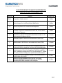
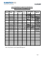
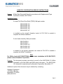
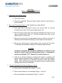
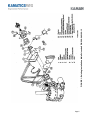
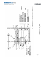
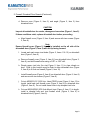
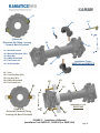
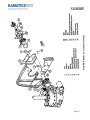
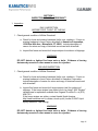
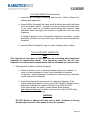
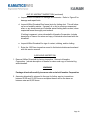
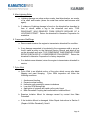
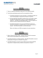
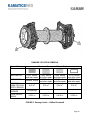
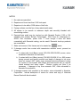
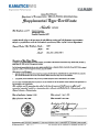
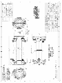
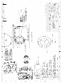
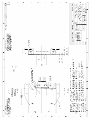
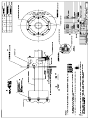
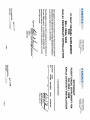
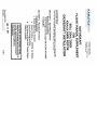
Service Instruction Number
SIN2348 Revision K
Installation, Maintenance, and Repair of the KAflex®
Driveshaft for the Bell 206A and 206B Helicopter.
KAMATICS CORPORATION SERVICE INSTRUCTION NUMBER 2348
This Service Instruction consists of the following sections:
1. KAflex® Driveshaft Retrofit
2. KAflex Driveshaft Removal and Installation
3. KAflex Driveshaft Inspection
4. KAflex Driveshaft Maintenance
5. KAflex Driveshaft Repair
6. Supplemental Type Certificate
7. SKCP2782 Installation Drawing
8. Weight and Balance
The KAflex® Driveshaft Installation Kit in accordance with drawing SKCP2782 contains
the following parts (please check parts before continuing):
1. KAflex Driveshaft P/N SKCP2348-101
2. Firewall Cover kit P/N SKCP1322-3
3. 12 MS20613-3C Universal Head CRES Rivets- 6 required
(Included in SKCP1322-3 Firewall Cover)
4. 2 MS20427M3 Flush Monel Rivet – 1 required
(Included in SKCP1322-3 Firewall Cover)
5. Certificate of Compliance
6. Kamatics Corporation Service Instruction Number 2348
7. Historical Service Record (in back pocket of Service Instruction)
The following tools will be required to complete Section 1 of this Service Instruction:
1. 3/32” or .093” drill bit
2. Electric or air drill motor
3. Rivet gun with 3/32” set
4. 0-100 in-lb torque wrench
5. Workaid, KAflex Frame Compressor P/N SKSP1321, SKSP1375 OR
SKSP1404
6. Machine shop facilities if aircraft is equipped with a BHTI P/N 206-030539-101 or -005 Lord (Barry) Transmission Isolation Mount.
Page 1
LOG OF REVISIONS TO KAMATICS CORPORATION
SERVICE INSTRUCTION NUMBER 2348
Revision
Basic
Reason
Prepared By
Preparation of basic manual
J. Miller
A
Added changes for Lord (Barry) Mount Modification.
J. Miller
B
Remove requirement for annual removal/inspection.
J. Miller
C
D
Change inspection intervals to agree with those of other nearby
drivetrain components, added alternate work aid, correct callout
for number of fasteners.
Changed firewall cover to have pre-drilled holes. Improved
Instructions in general. Changed driveshaft dash number to -101.
Added weight and balance section.
J. Miller
J. Parekh
E
Increased inspection interval from 4500 hours to 6000 hours.
J. Parekh
F
Added inertia kit SKCP3244 to be installed with riveted TRDS
J. Parekh
G
Added more caution and warning notes to emphasize daily, 100
hours and 1500 hour inspection and record in historical data card.
J. Parekh
H
Included .370” max. installation compression limit (install tool).
Added Inspection Criteria for Compressor Stall/Surge and Pylon
Whirl. Installation Drawing SKCP2782 now at Revision “F” (added
corrosion protection coating note). Updated workaid illustrations
J. Parekh
J
Revised to account for possible change in OEM hardware due to
EASA SIB No: 2012-06R2.
A. Zink
K
Additional revisions related to EASA SIB No: 2012-06R2.
Kamatics-supplied MS21042 nuts removed from locations
connecting the Kaflex driveshaft to the helicopter.
A. Zink
Page 2
LOG OF REVISIONS TO KAMATICS CORPORATION
SERVICE INSTRUCTION NUMBER 2348
Affected Pages
Section
Section
Sections
1
5
2,3,4,8
Revision
Letter
Revision
Date
Basic
10/05/1990
A
12/12/1991
B
03/09/1994
C
03/20/1996
1,9,10
D
11/26/1997
1-5,710,12,13
20,21,22
14-19
E
09/15/1999
1,2,4,5,11
21,22
17-20
F
05/02/2001
1-4,9-11
G
02/21/2005
2
22
16-20
H
07/15/2013
5,7
23,24
17,18
J
01/20/2015
10
16
K
03/30/2015
10
16
1,9 & ff
19 & ff
DER Approval
Section
Section
1
5
Kamatics
Approval
14 & ff
13
14-20
15,30
N/A
N/A
N/A
N/A
*Note: Only Sections 1 and 5 require DER approval.
Page 3
KAMATICS CORPORATION SERVICE INSTRUCTIONS
Subject:
KAflex Main Driveshaft Retrofit in accordance with Supplemental Type
Certification Number SH7767SW.
Installation Notes:
If riveted Tail Rotor Drive Shaft (TRDS), Bell part number:
206-040-383-101
206-040-383-105
206-040-387-103
206-040-387-105
206-040-387-107
is installed on the aircraft, Kamatics inertia kit P/N 3244 is needed to
complete the KAflex installation.
If rotor brake assembly, Bell part number:
206-706-034-3
206-706-034-7
206-706-034-101
206-706-034-103
206-706-034-105
is installed on the aircraft, Kamatics rotor brake kit P/N 2975 is needed to
complete the KAflex® installation.
Note
For KAflex inertia kit P/N SKCP3244 or rotor brake installation kit P/N SKCP2975,
please contact Kamatics Corporation.
Purpose: This document provides instruction for retrofit of the SKCP2348-101 KAflex
Driveshaft on the Bell 206A and 206B series helicopters. The SKCP2348101 driveshaft is manufactured by Kamatics Corporation, Bloomfield, CT.
Additional copies of this document may be obtained by contacting:
Kamatics Corporation
1330 Blue Hills Ave.
Bloomfield, CT 06002
(860) 243-9704
Page 4
SECTION 1
KAflex DRIVESHAFT RETROFIT
1. Preparation and General Notes
a. Disconnect battery.
b. Remove transmission fairing and open engine cowling to gain access to
main driveshaft.
2. Removal of Driveshaft (Figure 1) P/N 206-040-100 or 206-040-015
a. From right side of helicopter, remove two screws (Item 6) securing
driveshaft cover (Item 8) and cone assembly (Item 18).
b. Remove eleven screws (Item 14) securing driveshaft door (Item 5) to aft
side of forward firewall (Item 15). Remove driveshaft door (Item 5) and
gasket (Item 4) from aircraft.
c. Remove four bolts (Item 3), eight washers (Item 2), and four nuts (Item 1)
attaching forward driveshaft coupling to input adapter on transmission.
d. Remove four bolts (Item 9), eight washers (Item 10) and four nuts (Item
11) attaching aft driveshaft coupling to freewheeling adapter flange.
CAUTION
Compress couplings with Kamatics installation tool (Figure 3) just
enough to release them from mating adapter flange. If couplings are
compressed beyond 0.370”, damage to coupling may occur.
e. Push aft on forward coupling to compress flex frames in couplings and
obtain clearance between forward driveshaft coupling and input adapter
flange. Move forward end of driveshaft outboard to clear input adapter
flange. Move driveshaft assembly aft passing forward coupling through
opening and remove from helicopter.
3.
Firewall, Driveshaft Door Rework (Figures 1 and 2)
a. Gain access to driveshaft door (Figure 2, Item 9)
b. Remove both halves of cone assembly (Figure 1, Item 18)
c. Remove driveshaft cover assembly (Figure 1, Items 8)
Page 5
Page 6
FIGURE 1: Existing Installation Main Driveshaft P/N 206-040-100-13
Page 7
FIGURE 2: Looking FWD
3. Firewall, Driveshaft Door Rework (Continued)
d. Remove cone (Figure 2, Item 2) and angle (Figure 2, Item 3) from
driveshaft door.
CAUTION
Inspect driveshaft door for cracks, damage and corrosion (Figure 1, Item 5).
If these conditions exist, replace driveshaft door before proceeding.
e. Align firewall cover (Figure 2, Item 6) and secure with two screws (Figure
2, Item 8).
Note
Ensure firewall cover (Figure 2, Item 6) is installed on the aft side of the
driveshaft door (Figure 2, Item 9) with the lip facing forward.
f. Locate and mark seven rivet holes (Figure 2, Items 11 & 12) on driveshaft
door (Figure 2, Item 9)
g. Remove firewall cover (Figure 2, Item 6) from driveshaft door (Figure 2,
Item 9), and drill firewall cover using a 3/32” or .093” drill.
h. Dimple upper rivet hole (for rivet Figure 2, Item 11) to clear dimple on
door. Rivet in this location must be flush to allow driveshaft door (Figure
2, Item 9) to fit flush on firewall (Figure 2, Item 10).
i.
Install firewall cover (Figure 2, Item 6) on driveshaft door (Figure 2, Item 9)
and secure with two screws (Figure 2, Item 8).
j.
Cut six MS20613-3C (3/32 Univ. Head CRES) rivets (Figure 2, Item 12) to
length, install and rivet firewall cover (Figure 2, Item 6) to driveshaft door
(Figure 2, Item 9). Do not install these rivets in top dimpled rivet hole.
k. Cut one MS20427M3 (3/32 flush Monel) rivet (Figure 2, Item 11) to length,
install in dimpled hole and rivet firewall cover (Figure 2, Item 6) to
driveshaft door (Figure 2, Item 9).
Page 8
4. Modification to Lord (Barry) Transmission Isolation Mount,
P/N 206-030-539-101 or -005
Note
Modification is necessary only with the Lord (Barry) Transmission Isolation
Mount BHTI P/N 206-030-539-101 or -005, the mount with aluminum cover
plates. The Lord Transmission Isolation Mount, BHTI P/N 206-030-539-003
with black elastometric cover, has additional clearance and modification is
not necessary. Since Barry has merged with Lord, the transmission
isolation mounts with aluminum covers may have “Lord” name plate on
them. Older mounts may still have “Barry” name plate on them.
a. Remove the transmission mount per BHTI service instructions.
b. Modify the Lord (Barry) Isolation Mount in accordance with SKCP2782
Sheet 3, Section 7.
c. Reinstall the mount according to the BHTI Maintenance Manual.
Note
Do not use unauthorized shims, adhesives or sealants between the Lord
(Barry) Mount and the cabin roof. Refer to BHTI Technical Bulletin 206-7714 if interference exists between the Lord (Barry) Mount and roof top rivets.
5. KAflex Driveshaft Installation (Figures 3 and 4)
Note
Inspect KAflex Driveshaft in accordance with Section 3, “KAflex Driveshaft
Inspection” and Section 5, “Repair of KAflex Driveshaft” before proceeding
with the installation.
a. Install Workaid on KAflex Driveshaft by installing Workaid collars over
driveshaft and attach tightening screws with nuts (Figure 3). Compress
forward frames. Position lugs of the two tightening screws over nut
attaching end fitting to flex frame of KAflex Driveshaft (Figure 3). The
KAflex Driveshaft will be installed with the serial number aft to facilitate
future maintenance and inspections. Orientation does not affect function
of the KAflex Driveshaft.
CAUTION
If the lugs of the tightening screws are installed over the nut attaching flex
frame to flex frame, the flex frames can be over compressed and the flex
frames are likely to be damaged.
Page 9
5. KAflex Driveshaft Installation (continued)
b. Compress KAflex Flex frames approximately ¼” by tightening the workaid
nuts.
c. Install KAflex Driveshaft in the aircraft with serial number facing aft.
d. Loosen workaid nuts and allow KAflex Driveshaft to extend, aligning pilots
on KAflex Driveshaft to Quill Adapter and Freewheeling Adapter. Remove
workaid.
e. Install four bolts (Figure 4, Item 3) at the forward portion of the KAflex
Driveshaft, ensuring bolt heads face aft. Do not put washers under bolt
heads.
f. Install eight washers (Figure 4, Item 2), and four nuts (Figure 4, Item 1) on
the four bolts. Do not put washers under bolt heads.
g. Install four bolts (figure 4, Item 9) at the aft portion of the KAflex
Driveshaft, ensuring bolt heads face forward. Do not put washers under
bolt heads.
h. Install eight washers (Figure 4, Item 10), and four nuts (Figure 4, Item 11)
on the four bolts. Do not put washers under bolt heads.
Note
If a riveted TRDS is installed in the aircraft, an inertia kit SKCP3244 is
required with this KAflex Driveshaft (see Section 1, Page 4). In that case
use the hardware (bolts, nuts, washers) supplied with the inertia kit for the
aft portion of the driveshaft. Install the inertia kit as shown on the drawing
SKCP3244 enclosed in Section 7.
i.
Torque four nuts (Figure 4, Item 11) in accordance with OEM installation
instructions, ensuring pilot is engaged and KAflex Driveshaft end fitting
flanges are flat against the freewheeling adapter.
j.
Apply torque stripes to 4 aft KAflex mounting bolts and nuts.
k. Torque four nuts at the forward portion of the KAflex Driveshaft (Figure 4,
Item 1) in accordance with OEM installation instructions, ensuring pilot is
engaged and KAflex Driveshaft end fitting flanges are flat against the Quill
Adapter.
l.
Apply torque stripes to 4 forward KAflex mounting bolts and nuts.
Page 10
A5
A2
A1
A3
A
(View A-A)
A4
Driveshaft Aft Fitting, Looking
Forward, Main Driveshaft
A1.
A2.
A3.
A4.
A5.
A6.
Workaid Collars
Workaid Brackets (2PL)
Wing Nut
KAflex Driveshaft
Flex Frame Nut
Serial Number
B1.
B2.
B3.
B4.
B5.
Yoke
Foot Brackets (2PL)
Hex Nut (2PL)
KAflex Driveshaft
Flex Frame Nut
A5
A
Installation Tools:
SKSP1321 or SKSP1375
A6
A1
B3
B2
B4
B5
B1
B
Installation Tool:
SKSP1404
(View B-B)
Driveshaft Forward Fitting,
Looking Aft, Main Driveshaft
B
B5
B3
B2
FIGURE 3: Installation of Workaid
(Installation Tool SKSP1321, SKSP1375 or SKSP1404)
Page 11
Page 12
FIGURE 4: KAflex Driveshaft Installation
6. Driveshaft Door Installation (Figure 4)
a. Install firewall cover (Figure 2, Item 7) using 4 screws (Figure 2, Item 8).
b. Install driveshaft door (Figure 2, Item 5) and gasket, (Figure 2, Item 4)
using 11 screws (Figure 2, Item 8) and remaining 2 screws (Figure 2, Item
8).
c. Turn KAflex® Driveshaft by hand to ensure proper operation and
clearance. Check clearance between the driveshaft and firewall
covers (Figure 2, Items 6 &7) at four positions, 3 o’clock, 6 o’clock, 9
o’clock and 12 o’clock. Minimum clearance must be 0.450”. If the
clearance is less than 0.450”, it can be adjusted by loosening 4 screws
(Figure 2, Item 8) and sliding firewall cover (Item 7) or by loosening 11
screws (Item 14) and sliding driveshaft door (Item 5) within the clearance
of the screw hole and then re-tightening the screws.
CAUTION
Ensure aircraft rotors are free to turn, and will not strike any surface.
d. Carefully check all electrical lines, fuel lines, hydraulic lines, and bleed air
lines for interference or looseness. Route and secure all lines in
accordance with AC43.13-1A chapters 10 & 11.
e. Close engine cowling and install transmission fairing.
f. Connect battery.
g. Ground run aircraft.
h. Complete Historical Service Record, and applicable logbook entries. It
should be updated and all the required entries made, any time a service or
inspection is performed on the driveshaft.
Page 13
SECTION 2
KAflex DRIVESHAFT REMOVAL AND INSTALLATION
1. KAflex Driveshaft Removal (Figure 4)
a. Disconnect battery.
b. Remove transmission fairing and open engine cowling to gain access to
KAflex Driveshaft.
c. From right side of the helicopter, remove 15 screws (Figure 4, Item 14)
securing firewall cover (Figure 2, Item 7), and driveshaft door (Figure 2,
Item 9) to firewall. Remove firewall cover (Figure 4, Item 7) driveshaft
door (Figure 4, Item 5), and gasket (Figure 4, Item 4) from aircraft.
d. Remove 4 nuts (Figure 4, Item 1), 8 washers (Figure 4, Item 2) and 4 bolts
(Figure 4, Item 3) securing the forward portion of the KAflex Driveshaft.
e. Remove 4 nuts (Figure 4, Item 11), 8 washers (Figure 4, Item 10), and 4
bolts (Figure 4, Item 9) securing the aft portion of the KAflex Driveshaft.
f. Install workaid per Figure 3 on KAflex Driveshaft by installing workaid
collars over driveshaft and attach tightening screws with nuts. Compress
forward frames. Position lugs of the two tightening screws over nut
attaching end fitting to the flex frame at aft end of KAflex Driveshaft. The
KAflex Driveshaft will be reinstalled with the serial number aft to facilitate
future maintenance and inspections. Orientation does not affect function
of the KAflex Driveshaft.
g. Compress KAflex
approximately ¼”.
Flex
Frames
by
tightening
the
workaid
nuts
h. Remove KAflex Driveshaft from aircraft.
Page 14
2. KAflex Driveshaft Installation (Figure 4)
a. Install workaid per Figure 3 on KAflex Driveshaft by installing workaid
collar(s) over driveshaft and attach tightening screws with nuts. Position
lugs of the two tightening screws over nut attaching end fitting to flex
frame of KAflex Driveshaft (Figure 3). The KAflex Driveshaft will be
installed with the serial number aft to facilitate future maintenance and
inspections. Orientation does not affect function of the KAflex Driveshaft.
CAUTION
If the lugs on the tightening screws are installed incorrectly over the nut
attaching flex frame to flex frame, the flex frames can be over compressed
and the flex frames are likely to be damaged.
b. Compress KAflex Flex frames approximately ¼” by tightening the workaid
nuts.
c. Install KAflex Driveshaft in the aircraft with serial number facing aft.
d. Loosen workaid nuts and allow KAflex Driveshaft to extend, aligning pilots
on KAflex Driveshaft to Quill Adapter, and Freewheeling Adapter.
Remove workaid.
e. Install four bolts (Figure 4, Item 3) at the forward portion of the KAflex
Driveshaft, ensuring bolt heads face aft. Do not put washers under bolt
heads.
f. Install eight washers (Figure 4, Item 2), and four nuts (Figure 4, Item 1) on
the four bolts. Do not put washers under bolt heads.
g. Install four bolts (Figure 4, Item 9) at the aft portion of the KAflex
Driveshaft, ensuring bolt heads face forward. Do not put washers under
bolt heads.
h. Install eight washers (Figure 4, Item 10) and four nuts (Figure 4, Item 11)
on the four bolts. Do not put washers under bolt heads.
Note
If a riveted TRDS is installed in the aircraft, an inertia kit SKCP3244 is
required with this KAflex Driveshaft (see Section 1, Page 4). In that case
use the hardware (bolts, nuts, washers) supplied with the inertia kit for the
aft portion of the driveshaft. Install the inertia kit as shown on the drawing
SKCP3244 enclosed in Section 7.
Page 15
a. Torque four nuts (Figure 4, Item 11) in accordance with OEM installation
instructions, ensuring pilot is engaged and KAflex Driveshaft end fitting
flanges are flat against the Freewheeling Adapter.
b. Apply torque stripes to 4 aft KAflex mounting bolts and nuts.
c. Torque four nuts at the forward portion of the KAflex Driveshaft (Figure 4,
Item 1) in accordance with OEM installation instructions, ensuring pilot is
engaged and KAflex Driveshaft end fitting flanges are flat against the Quill
Adapter.
d. Apply torque stripes to 4 forward KAflex mounting bolts and nuts.
3. Driveshaft Door Installation (Figure 4)
a. Install firewall cover (Figure 4, Item 7) using 4 screws (Figure 4, Item 8).
b. Install driveshaft door (Figure 4, Item 5) and gasket (Figure 4, Item 4) using
11 screws (Figure 4, Item 8)
c. Turn KAflex Driveshaft by hand to ensure proper operation and
clearance. Check clearance between the driveshaft and firewall
covers (Figure 2, Items 6 & 7) at four positions, 3 o’clock, 6 o’clock, 9
o’clock and 12 o’clock. Minimum clearance must be 0.450”. If the
clearance is less than 0.450”, it can be adjusted by loosening 4 screws
(Figure 2, Item 8) and sliding firewall cover (Figure 4, Item 7) or by
loosening 11 screws (Figure 4, Item 14) and sliding driveshaft door (Figure
4, Item 5) within the clearance of the screw hole and then re-tightening the
screws.
CAUTION
Ensure aircraft rotors are free to turn, and will not strike any surface.
d. Carefully check all electrical lines, fuel lines, hydraulic lines, and bleed air
lines for interference or looseness. Route and secure all lines in
accordance with AC43.13 – 1A chapters 10 & 11.
e. Close engine cowling and install transmission fairing.
f. Connect battery.
g. Ground run aircraft.
h. Complete Historical Service Record, and applicable logbook entries. It
should be updated and all the required entries made any time a service or
inspection is performed on the driveshaft.
Page 16
SECTION 3
INSPECTION OF KAflex DRIVESHAFT
1. Inspection
DAILY INSPECTION
BEFORE FIRST FLIGHT OF THE DAY
1. Check general condition of KAflex Driveshaft.
a. Check for loose and missing hardware (bolts, nuts, washers). If loose or
missing hardware is found, return driveshaft to Kamatics Corporation,
1330 Blue Hills Ave., Bloomfield, CT 06002. Include description of
reason for return and copy of historical record card with driveshaft.
b. Inspect flex frame and mount bolt torque stripes for evidence of slippage.
WARNING
DO NOT disturb or tighten flex frame nuts or bolts. Evidence of turning
fasteners by wrench or other means is cause for rejection.
100 HOUR INSPECTION
1. Check general condition of KAflex Driveshaft.
a. Check for loose and missing hardware (bolts, nuts, washers). If loose or
missing hardware is found, return driveshaft to Kamatics Corporation.
Include description of reason for return and copy of historical record card
with driveshaft.
b. Inspect flex frame and mount bolt torque stripes (red) for evidence of
slippage. If the torque stripes have faded, touch up using F-925 “Skydrol”
resistant seal or equivalent available from Organic Products Co. at (972)
438-7321.
If the torque stripes are yellow, contact Henkel North America.
http://www.henkelna.com to obtain a touch up kit (Loctite E-20HP Hysol
Epoxy Adhesive, Fast Setting).
WARNING
DO NOT disturb or tighten flex frame nuts or bolts. Evidence of turning
fasteners by wrench or other means is cause for rejection.
Page 17
100 HOUR INSPECTION (continued)
c. Inspect KAflex Driveshaft for damage and corrosion. Refer to Figure 5 for
damage and repair limits.
d. Inspect KAflex Driveshaft flex frame joints for fretting dust which will show
up as red metallic residue. If grease, oil or dirt is covering suspected area,
or any doubt exists as to whether actual fretting has occurred, clean
suspected areas thoroughly and recheck in conjunction with next daily
inspection.
If fretting is apparent, return Driveshaft to Kamatics Corporation. Include
description of reason for return and copy of historical record card with the
driveshaft.
e. Inspect KAflex Driveshaft for sign of contact, rubbing, and/or chafing.
OUT OF AIRCRAFT INSPECTION
Note
This inspection is to be done at 1500 hour intervals (coinciding with removal and
inspection of freewheeling clutch). This inspection reads like the 100 hour
inspection, but will be more comprehensive with the driveshaft out of the aircraft.
1. Check general condition of KAflex Driveshaft.
a. Check for broken, loose, or missing hardware (bolts, buts, washers). If
loose or missing hardware is found, return driveshaft to Kamatics
Corporation. Include description of reason for return and copy of historical
record card with the driveshaft.
b. Inspect flex frame bolt torque stripes for evidence of slippage. If the
torque stripes have faded, touch up using F-925 “Skydrol” resistant seal or
equivalent available from Organic Products Co at (972) 438-7321.
If the torque stripes are yellow, contact Henkel North America.
http://www.henkelna.com to obtain a touch up kit (Loctite E-20HP Hysol
Epoxy Adhesive, Fast Setting).
WARNING
DO NOT disturb or tighten flex frame nuts or bolts. Evidence of turning
fasteners by wrench or other means is cause for rejection.
Page 18
OUT OF AIRCRAFT INSPECTION (continued)
c. Inspect KAflex Driveshaft for damage and corrosion. Refer to Figure 5 for
damage and repair limits.
d. Inspect KAflex Driveshaft flex frame joints for fretting dust. This will show
up as red metallic residue. If grease, oil or dirt is covering a suspected
area, or any doubt exists as to whether actual fretting has occurred, clean
suspected areas thoroughly and recheck.
If fretting is apparent, return driveshaft to Kamatics Corporation. Include
description of reason for return and copy of historical record card with the
driveshaft.
e. Inspect KAflex Driveshaft for sign of contact, rubbing, and/or chafing.
f. Enter the 1500 hour inspection record in the historical data card enclosed
with this service manual.
6,000 HOUR INSPECTION
1. Remove KAflex Driveshaft for factory inspection. Return to Kamatics
Corporation. Include description of reason for return and copy of historical log
with driveshaft.
WARNING
Package driveshaft carefully to ensure safe arrival at Kamatics Corporation
2. Assuming driveshaft is returned to the user for further service, inspections
between 6,000 and 12,000 hours or multiples thereof will be the same as
between new and 6,000 hours.
Page 19
2. KAflex Driveshaft Conditional Inspection
Note
The following inspections detail special inspection instructions applicable to
KAflex Driveshaft. Refer to appropriate Bell and Allison maintenance manuals for
airframe and engine special inspection instructions.
1. Overtorque
a. 110-120% overtorque, perform a daily inspection on KAflex Driveshaft.
b. 120+% overtorque, perform a 100 hour inspection on KAflex Driveshaft.
2. Overspeed
a. 114+% overspeed, no KAflex Driveshaft inspection necessary.
3. Sudden Stoppage
a. Perform a 100 hour inspection on the KAflex Driveshaft. Inspect
freewheeling clutch assembly for evidence of overtorque. If clutch sprags
are chipped or broken, if there is evidence of static brinelling of clutch
races or other evidence of torsional overload, return driveshaft to
Kamatics Corporation with information described in the Section on 6,000
hour inspection.
4. Hard Landing
a. If any of the following components do not pass their respective inspection
criteria as detailed in chapter 5, “Inspections” of the Bell 206A/B
Maintenance Manual, the KAflex Driveshaft must be returned to Kamatics
as described in the Section of this manual on inspection after 6,000 hours:
i.
ii.
iii.
iv.
v.
Main Rotor Hub
Main Rotor Mast
Main Transmission, Main Transmission Mounts, Drag Pin, Drag Plate
Freewheeling Clutch Assembly
Engine or Engine Mounts
b. Even if none of the items in Item ‘a’ above show the effects of the hard
landing, perform a 100 hour inspection on the KAflex Driveshaft, and
inspect the top of the isolation mount (P/N 206-030-539-003, -101 or -005)
if installed. If contact has occurred, refer to Section 5.
Page 20
5. After Lightning Strike
a. Lightning damage can show as burn marks, heat discoloration, arc marks,
or as small weld marks (where the metal has melted and became solid
again).
b. If evidence of lightning damage is found on the driveshaft as described in
Item ‘a’ above, attach a tag to the driveshaft and write, “THIS
DRIVESHAFT WAS REMOVED FROM SERVICE BECAUSE OF A
LIGHTNING STRIKE”. Return the driveshaft to Kamatics Corporation for
evaluation.
6. Compressor Stall/Surge
a. Remove and examine the engine-to-transmission driveshaft for condition.
b. If any damage suspected to be related to the compressor stall or surge is
found, make an entry on the Historical Service Record, and attach a tag
on the driveshaft and write “THIS COMPONENT WAS REMOVED FROM
SERVICE BECAUSE OF A COMPRESSOR STALL/SURGE”. Return the
driveshaft to Kamatics Corporation for factory inspection.
c. If no defects were detected, return the engine-to-transmission driveshaft to
service.
7. Pylon Whirl
a. Pylon Whirl is an elliptical motion of the pylon which occurs after blade
flapping and mast bumping. Pylon Whirl inspection will follow the
following conditions:
i.
ii.
iii.
iv.
v.
vi.
An abnormal landing
Excessive slope landing
Helicopter was operated in severe turbulence
Low rotor RPM during flight
Application of extreme and rapid cyclic control input
Main Driveshaft Coupling has contacted the Isolation Mount
b. Examine Isolation Mount for damage caused by contact from Main
Driveshaft.
c. If the Isolation Mount is damaged, follow Repair Instructions in Section 5
(Repair of KAflex Driveshaft), Note 8.
Page 21
SECTION 4
MAINTENANCE OF KAflex DRIVESHAFT
1. There is no periodic maintenance requirement for the KAflex Driveshaft.
2. The following maintenance practices will be incorporated as follows:
a. The KAflex Driveshaft is not field overhauled. The KAflex Driveshaft can
only be disassembled for inspections at Kamatics Corporation.
b. Any time the KAflex Driveshaft is transferred from one aircraft to another,
the KAflex Driveshaft does not require a complete disassembly and
inspection. The KAflex Driveshaft does require a 100 hour inspection at
this time, and then at each aircraft 100 hour inspection.
c. The KAflex Driveshaft is to be removed at 6,000 hours and sent to
Kamatics Corporation for complete factory inspection and overhaul as
required. The KAflex Driveshaft is not field overhauled.
Refer to the Section on 6,000 hour inspection for return instructions.
SECTION 5
REPAIR OF KAflex DRIVESHAFT
1. Refer to Figure 5 for repair criteria. All blends shall be smooth at maximum
depth and smoothly blended with surrounding surfaces.
2. The KAflex Driveshaft is not field overhauled. The KAflex Driveshaft can only be
disassembled for inspection at Kamatics Corporation.
3. The KAflex Driveshaft is to be removed at 6,000 hours and sent to Kamatics
Corporation for complete factory overhaul and inspection as required.
Page 22
DAMAGE LOCATION SYMBOLS
Type of Damage
MECHANICAL
CORROSION
MAXIMUM
AREA PER FULL
DEPTH REPAIR
NUMBER OF
REPAIRS
EDGE DENTS,
NICKS
Maximum Damage and Repair Depth
0.001” before
and after repair
0.005” before
and after repair
0.005” before
Surface, no pits
and after repair
0.05 in2
0.005” before
and after repair
0.005” before
and after repair
0.015” before
and after repair
0.010” before
and after repair
0.10 in2
0.25 in2
0.25 in2
0.010 in
0.010 in
0.025 in
One per leg
0.001 in
FIGURE 5: Damage Limits – KAflex Driveshaft
Page 23
NOTES:
1. No cracks are permitted
2. Repairs must be no less than 1.000 inch apart.
3. Repairs not to be within 0.500 inches of bolt hole.
4. Faying surfaces must be free of any raised metal areas.
5. All repairs to be smooth at maximum depth and smoothly blended with
surrounding surface.
6. Exposed bare metal may be touched up with Sermetel Product 1122 or 196
available from Praxair Surface Technologies, 1550 Polco St. Indianapolis In.
46222. Zinc Chromate, primer color T, even though it does not blend
cosmetically with Sermetel coating, can be used if Sermetel touch-up products
are unavailable.
7. Sides and corners of flex frames are to be treated as
areas.
8. If damage results from contact with transmission isolation mount, proceed as
follows:
a. If contact with Lord (Barry) mount (P/N 206-030-539-303) occurs, return
driveshaft to Kamatics for evaluation.
b. If contact with Lord (Barry) mount (P/N 206-030-539-101 or -005) occurs
during unusual and severe condition and depth of damage to top cover
does not exceed .025”, lightly stone smeared aluminum/ceramic coating
on corners of flex frames, end fittings and interconnect ears to remove
raised material and sharp edges. Restore coating per Note 6 as
necessary. If damage to top cover exceeds .025”, return driveshaft to
Kamatics for evaluation.
9. If damage exceeds limit specified in this section, return driveshaft to Kamatics
Corporation. Include description of reason for return and copy of Historical
Record Card with the driveshaft.
Page 24
SECTION 6
TYPE CERTIFICATE
Following is a copy of:
1. FAA Supplemental Type Certificate Number SH7767SW
2. EASA Supplemental Type Certificate 10052951.
Page 25
Page 26
Page 27
Page 28
SECTION 7
INSTALLATION DRAWING
Following are copies of the installation drawing in the STC 7767SW:
SKCP2782
SH 1, 2, 3
SKCP3244
SH 1
Page 29
SECTION 8
WEIGHT & BALANCE
The KAflex Main Driveshaft retrofit has negligible effect on weight and balance of the
helicopter.
Page 34
Page 35
Page 36
COMPONENT NAME:
PART NUMBER:
SERIAL NUMBER
PAGE
KAFLEX DRIVESHAFT
HISTORICAL SERVICE RECORD
OF
INSTALLATION DATA
DATE
INSTALLED
ON A/C NO.
BY
(ACTIVITY)
INSTALLED
AT A/C HRS.
COMP. HRS.
SINCE NEW
SINCE O/H
A/C HOURS
SCH. FOR
O/H
RETIRE
HRS. / DATE
REMOVAL DATA
DATE
REMOVED AT
A/C HRS.
COMP. HRS.
SINCE NEW
SINCE O/H
REASON FOR
REMOVAL
TECHNICAL DIRECTIVES AND HISTORY OF OVERHAUL
DIRECTIVE NUMBER
IF APPLICABLE
TIME/DATE
EFFECTIVITY
DESCRIPTION
COMPLIANCE
BY (ACTIVITY)
DATE
1,500 HOURS INSPECTION, 6,000 HOURS INSPECTION, AND ANY OTHER REPAIRS / MAINTENANCE PERFORMED ON THE DRIVESHAFT MUST BE RECORDED ON THIS
HISTORICAL DATA CARD.
ORIGINALLY
PLACED IN
SERVICE
COMPONENT NAME
SERIAL NUMBERS
PART NUMBER
NAME:
NO.:
NAME:
NO.:
NAME:
NO.:
NAME:
NO.:
NAME:
NO.:
NAME:
NO.:
NAME:
NO.:
NAME:
NO.:
NAME:
NO.:
NAME:
NO.:
INSTALLATION DATA
SCHEDULED
REMOVAL
ACCULULATED TIME ON
ASSEMBLY OR PART
DATE
DATE
COMPONENT
HOURS
AIRCRAFT
HOURS
DATE
SINCE NEW
COMPONENT
(HRS)
HOURS
SINCE
OVERHAUL
(HRS)
REMOVAL DATA
ACCUMULATED TIME ON
ASSEMBY OR PART
SINCE NEW
(HRS)
SINCE
OVERHAUL
(HRS)