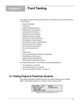
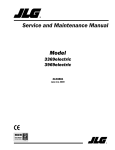
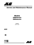
1
Merits
S1/S3 series
Rhino Service Manual
Nov.9.2006 V1
S1/S3 series-Rhino Service manual
Page
Introduction-------------------------------------------------------------------1
1.Service guide---------------------------------------------------------------1
2.Battery-----------------------------------------------------------------------1
2.1 When to replace the batteries-----------------------------------------1
2.2 To remove the batteries------------------------------------------------1
2.3 To install the batteries--------------------------------------------------2
2.4 Check battery charge---------------------------------------------------2
3. Motor, brush and Parking brake-----------------------------------------2
3.1 Motor---------------------------------------------------------------------2
3.2 Brushes-------------------------------------------------------------------4
3.3 Parking Brake-----------------------------------------------------------4
4. Tiller Instrument---------------------------------------------------------10
4.1 Tiller disassembly/assembly procedure----------------------------11
4.2 Throttle Potentiometer-----------------------------------------------13
4.3 Dash board ------------------------------------------------------------15
4.3.1 Analog Dash board------------------------------------------------15
4.3.2 Digital Dash board------------------------------------------------16
5. Examples of Electrical illustrated parts breakdown-----------------17
5.1 S1-series--------------------------------------------------------------17
5.2 S3-series--------------------------------------------------------------18
6. Scooter troubleshooting-------------------------------------------------19
(Typical problems and solution)
7. Controller-----------------------------------------------------------------22
7.1 Rhino connection and wiring---------------------------------------22
7.2 Programming Rhino--------------------------------------------------24
7.2.1 Setup Menu-------------------------------------------------------27
7.2.2 Option Menu-----------------------------------------------------32
7.2.3 Common programming errors---------------------------------34
7.3 Rhino Diagnostics and fault finding-------------------------------35
7.3.1 Diagnose fault---------------------------------------------------35
7.3.2 flash code--------------------------------------------------------38
8.Charger--------------------------------------------------------------------39
8.1 Operation instruction------------------------------------------------39
8.2 LED indication-------------------------------------------------------40
8.3 Troubleshooting------------------------------------------------------40
9. Scooter diagnostic flow chart------------------------------------------42
Introduction
The purpose of this manual is to provide dealers and/or distributors with the
product information and instructions that are required for servicing the
S1/S3 series electrical scooter.
1 Service Guide
n
n
n
n
n
n
n
n
Batteries
Motors, Brush and brake
Tiller instrument
Electrical illustrated parts breakdown
Troubleshooting
Dynamic Rhino controller
Charger
Scooter diagnostic flow chart
WARNING
Before performing any maintenance or service, turn the power off.
NEVER allow tools and/or battery cable(s) to contact BOTH the battery
terminal(s) or the post(s) at the same time. An electrical short may occur
resulting in serious personal injury and/or damage. It is strongly
recommended that battery installation and/or replacement should be
done only by a qualified technician.
2 Batteries
n Battery type: Lead-acid *2 pieces
2.1 When to replace the batteries
The batteries may have to be replaced should one of the following
conditions occurs:
n The scooter’s driving distance decreases significantly.
n Incomplete charge.
n The Charging cycle becomes significantly longer or shorter than
before.
2.2 To Remove the Batteries
1. Remove the seat and shroud and unplug rear lights connector.
1
2. Disconnect the wiring harness from the batteries by removing
the screws.
3. Remove the batteries from the scooter base.
2.3 To install the Batteries
1. Install two new batteries into the power chair base.
2. Connect the wiring harness to the batteries. Refer to“Electrical
illustrated parts breakdown” diagram.
3. Confirm the battery supply voltage. (the battery voltage to the
controller should be at least 25VDC)
4. Plug rear lights connector and cover the shroud and install the
seat.
2.4 Checking Battery Charge:
1. Connect the voltmeter negative probe to controller power-.
2. Connect the voltmeter positive probe to controller power+.
3. The voltmeter should measure 23-27 volts (i.e. Battery
Voltage).
4. If the voltage is negative, check for correct battery wiring
polarity. Ensure that batteries are connected correctly.
5. If the voltage reading is zero, check for wiring open circuits or
battery wiring polarity.
6. Charge the batteries completely before driving.
3 Motor, brush and parking Brake
3.1 Motor:
The 24V motors are specifically designed for use on electrical scooter.
The motors incorporate a metal-cased parking brake. The parking brake
assembly and brushes are protected by a metal cover. The motor frame
is integral with the cast aluminum gearbox housing that forms a strong
and compact unit. An easy-to-operate brake lever engages/releases the
magnetic brake for manual pushing of the scooter.
Connections and Wiring
1. Each motor has four wires of two different sizes that require
connection. Note that the red and blue(or black) wire
connections will affect the motor orientation.
2. Upon completing all wirings the loom must be fastened to the
frame to minimize strain on the connections.
2
3. Lift the wheels before making the battery connection and
check if the drive system functions correctly.
4. Ensure that the scooter’s power system is equipped with a
circuit breaker or fuses.
Testing
Check the motors and control system when the installation is
completed. Note the following points:
The circuit breaker or fuses must be included in the power circuitry.
n Lift the wheels off the ground;
n Do not arc cables to check for power.
n Use a multimeter to check the voltage.
Operation of Brake lever
When it is desired to manually push the scooter, the brake lever is
easily released. Simply push/pull the lever on the magnetic brake.
Labels are available for indicating the status of the brake lever.
Maintenance and Servicing
The motor is a low-maintenance-required motor and except for
periodic checkup, requires no further maintenance under normal
conditions. The batteries should be disconnected during any
maintenance procedure and in fact their complete removal from the
scooter may help access.
n Check system regularly.
n Check for loose, damaged or corroded connectors and
terminals.
n Replace damaged cabling.
n Check motor mountings for tightness.
n Clean motor and control system components with a
damp cloth.
n The cover may be removed to check the brush length.
n Check for oil or grease leaks around the seals, output
shaft, and brake lever.
n Check motor for increased backlash or play, excessive
noise or other indications of the gear wear-out.
3
Warning:
Do not use the motor if there is any indication of damage or if
abnormities such as: damage to the case, grease leakage, abnormal
response as well as excessive backlash or play, noise, heat, smoke
and/or arcing are present.
Ensure that the motor is securely fastened to the transaxle and the
wheel securely fastened to the transaxle.
3.2 Motor Brushes
Each motor contains two or four carbon brushes which may require
replacement after operating the scooter a long period of time. Brush
replacement is a simple operation:
n Disconnect the motor.
n Remove the end cover to allow access.
n Remove the brush.
n Check the commutator for excessive wear or unusual
burns or erosion marks.
n Reverse the above processes to install the new brush,
ensuring that the brush is still able to slide in the brush
guide.
n Ensure the springs seat properly on the brush and the
brush wire is placed properly.
Note:
Ensure correct insulation between motor case and motor wires (refer
ISO 7176-14).
n Always replace all the brushes in both motors at the
same time.
n Run brushes in for several hours in the forward
direction. Ensure that the parking brake is released when
operating the motor. (This reduces brush bounce which
causes arcing and in turn generates RFI and audible noise.)
3.3 Parking Brake:
Poor parking brake holding ability indicates the need for replacing the
parking brake assembly.
n Disconnect the motor.
n Remove the cover to allow access.
n Cut/solder the wires of the parking brake. Avoid excess strain
4
on the wires.
n Remove the screws that hold the parking brake assembly
together.
n Reverse the process to install the new parking brake
assembly.
n Check the armature which must rotate freely with the parking
brake disengaged.
Parking brake replacing procedure:
5
6
7
8
9
4. Tiller Instrument
In case tiller instruments are to be checked or replaced, tiller shroud must be
dismantled first to allow access.
10
4.1Tiller disassembly/assembly procedure;
11
12
B: Tiller assembly procedure:
You can just backward the disassembly procedure to assemble the tiller. Remember to
tighten every screw and make sure every connector is plugged firmly.
4.2 Throttle Potentiometer( POT):
In some cases, scooter can not move results from POT problems. There are
three typical POT problems.
1. Speed POT wire broken or short-circuited(Rhino flash code 7)
13
Check if wires shorted or connector loose.
2. Speed POT out of range(Rhino flash code 7)
Measure the resistance between “1”and “3”of the potentiometer. It must be
5KΩ±10%. If not, Replace the potentiometer.
3.Speed POT not in neutral position(Rhino flash code 6)
Measure the resistance between “1”and “2”of the potentiometer. It must be
2.5KΩ±10%. If not, recalibrate the neutral position.
Measure the resistance between “2”and “3”of the potentiometer. It must be
2.5KΩ±10%. If not, recalibrate the neutral position.
1
2
3
Follow the wire color allocation--as picture below-- to solder the wire to the
potentiometer.
14
4.3 Dash board PCB
Dash board handles all accessories of the scooter, like lighting system, buzzer,
switches, battery gauge, charging inlet, keypad, speed adjust, throttle
potentiometer. Sometimes the accessory problems may turn out to be caused
by dash board PCB. Make sure all wires are not loose and all connector are
connected firmly. If everything is fine but the problem still remains, replace
the dash board PCB and test.
4.3.1 Analog dash board PCB
Following picture shows function of each connector on analog dashboard PCB.
13
1:Main cable connector
2:Key switch connector
3:Speed POT. Connector
4:Charger connector
5:Status LED connector
6:Hazard switch connector
7:Direction switch connector
8:Head light switch connector
9:Horn switch connector
10:Reduce speed switch connector
11:Turning reduce speed sensor connector
12:Lighting system connector
13. Speed adjust VR. Connector
15
4.3.2 Digital dash board PCB
2
4
1
5
6
7
8
3
1:Main cable connector
2:Key switch connector
3:Speed POT. Connector
4:Charger connector
5: Lighting system connector
6:Key pad connector
7: Turning reduce speed sensor connector
8: Reduce speed switch connector
16
5 Examples of electrical illustrated parts breakdown
5.1 S1-series scooter
17
5.2 S3-series scooter
18
6. Scooter troubleshooting ---Typical problems and solutions
Problem
Possible Causes Solution
Scooter does
not run
(Scooter not
moving and
lights do not
work using
battery, but
lights do work
when you plug
the charger into
the scooter and
also plug the
charger into the
wall outlet)
Undercharged
battery
Charge the battery. A new battery should have been charged
for at least 12 hours before using the vehicle for the first time
and up to 8 hours after each subsequent use.
Check all connectors. Make sure the charger connector is
tightly plugged into the charging inlet, and that the charger is
plugged into the wall.
Make sure power flow to the wall outlet is on.
Charger is not
working
You may check to see if your charger is working by using a
volt meter
Burned out fuse
Replace the fuse.
Scooter does
not run
(Scooter not
moving and
lights do work
using battery,)
Controller
diagnostic
(flashcode)
Follow controller section(Chapter 7.3.2) to see flashcode
meanings and Solutions.
Status LED fail
If status LED is dimly light or not working, replace with new
one.
Scooter not
moving and all
lights do not
work with only
batteries.
Burned out fuse
Replace the fuse
Scooter was
running but
suddenly
stopped
Controller trip
Loose
Check if wires/connections are tight.
wire/Connection
The controller will automatically shut off the power if the
motor is overloaded.
An excessive overload, such as too heavy a rider or too steep
a hill, could cause the controller to overheat. If the scooter
suddenly stops running, wait a few seconds and let the
controller cool down.
Tripped circuit
breaker or
burned out fuse
Check all wires and connectors to make sure they are tight.
The circuit breaker or fuse will automatically shut off the
power if overload or short-circuit happens. If the scooter
suddenly stops running, push the breaker to reset the circuit
19
or replace the fuse. Correct the conditions that caused the
breaker/fuse to trip and avoid repeatedly tripping the
breaker.
Short run time
(less than usual
per charge)
Undercharged
battery
Charge the battery. A new battery should have been charged
for at least 12 hours before using the scooter for the first
time and up to 8 hours after each subsequent use.
Check all wires and connectors. Make sure the charger plug
is tightly plugged into the charging socket, and that the
charger is plugged into the wall.
Make sure power flow to the wall outlet is on.
Scooter runs
sluggishly
Battery is old
and will not
accept full
charge
Even with proper care, a rechargeable battery does not last
forever. Battery life depends on scooter use and conditions.
Replace the battery if necessary.
Hand brake is
not adjusted
properly
Adjust the handbrake neutral position to reduce the friction
between brake disk and brake lining when brake is in neutral
position.
Tires are not
Make sure the tires have sufficient air but this usually is not
properly inflated the problem. The tires are inflated when shipped, but they
will lose some pressure between the point of manufacturing
and delivery. Check tire pressure and properly inflate the
tires.
Scooter is
overloaded
Make sure you do not overload the scooter by carrying too
much weight, going up a hill or towing objects behind the
scooter. If the scooter is overloaded, the controller may go
into protection mode and even shut off power to the motor.
Correct the driving conditions that caused the overload, wait
a few seconds, and then let the controller to recovery. Avoid
repeatedly overloading the scooter.
Hand brake is
not adjusted
properly
Adjust the handbrake neutral position to reduce the friction
between brake disk and brake lining when brake is in neutral
position.
Battery problem
Battery needs to be recharged. If after full charging the
20
batteries, the scooter still runs sluggishly. Replace the
batteries.
Sometimes, it may be too cold to operate the scooter. The
battery does not output much current at low temperatures
(below 5 degree C). It is too cold to operate.
Sometimes the
scooter doesn’t
run, but other
times it does
Loose wires or
connectors
Check all wires and all connectors to make sure they are
tight.
Switch bad
Check ON/OFF switch to make sure it is working properly.
Charger gets
warm during
use
Normal
response to
charger use
No action required. This is normal for chargers and is no
cause for concern. If the charger does not get warm during
use, it does not mean that it is not working properly.
Scooter can not
stop on a slope
Magnetic brake
are not working
properly
Possibly the brake lining is worn out. Replace the magnetic
brake.
Scooter takes
off - will not
stop
Throttle
potentiometer
problem
If the scooter is moving when you release the throttle , you
will need to adjust the potentiometer neutral position or
replace the throttle potentiometer.
After charging
for 8 hours, the
scooter battery
gauge does not
show a full
charge
Charger
Charger may be bad. Replace charger. This is the most
common.
Charger
connection
Charger connection on scooter is bad- usually a wire on the
back of the charger socket is loose.
Battery
Batteries are bad. Replace new ones
Loose
wire/connection
Check if wire/connection is tight.
Battery gauge
Battery gauge is bad. Replace new ones.
Bulb
Check /Replace light bulb.
All lights work
and scooter can
move but the
battery gauge
does not work.
Light is not
working.
Loose
Check if wire/connection is tight.
wire/Connection
Switch
Check switch function, If bad, replace new one.
Dashboard PCB
If light bulb , wire connection and switch are all OK,
Replace dashboard PCB.
21
7.Controller
The Rhino Controller
The RHINO scooter controllers includes:
•70A model (DS72K) for small-to-medium-size scooters
•110A model (DS112K) for medium-to-large-size scooters
•160A model (DS162K) for large scooters
7.1 RHINO Connections and Wiring
RHINO connections are located along the front of the case. The illustration
below indicates the different connectors and gives a section reference for
specific installation instructions. When all wiring has been completed, it must
be securely fastened to the scooter frame to ensure there is no strain on the
connectors or any chance of snagging.
Before making any connections to RHINO, disable the scooter by
one of the following means to prevent accidental movement or
arcing:
1) place the battery circuit breaker in the open position, or
2) disconnect the batteries
22
Typical Wiring Diagram for RHINO DS52K, DS72K, DS112K
23
Typical Wiring Diagram for RHINO DS162K
7.2 Programming RHINO
Using a hand-held programmer DZ-DS-PM, the controller settings can be
modified if desired.
DZ-DS-PM (Manufacturer Version) Programmer Tree
24
* Parameters available to DZ-DS-PD
** DS162K Only
RHINO Programming
Warning :
Only qualified personnel should make alterations to RHINO
programming. Incorrect or inappropriate programming of RHINO
can put the scooter into a dangerous state. Manufacturer accepts
no responsibility or liability for accidents caused by incorrect
programming. On completion of programming, we recommend a
drive test be carried out to ensure performance is as desired.
Note :If the scooter is turned off during programming, any changed settings
25
are not saved and RHINO defaults back to the previously programmed
settings.
26
Programmable Settings
The following settings can be modified so that a scooter can meet user’s needs.
Not all of these settings are available from the Scooter Programmer.
7.2.1 Setup Menu
These settings customize the scooter to user preferences and/or environment.
27
28
29
30
31
7.2.2 Options Menu
These settings are adjustable using a hand held programmer. Settings via the
programmer can be either ON or OFF.
32
33
7.2.3 Common Programming Errors
Sometimes after changing certain parameters, in particular, when customizing
the Motor Reverse and Pot Reverse settings, the scooter might not drive in the
way that was intended. Following is a matrix of Motor Reverse and Pot Reverse
34
settings and the impact they have on the motion of the scooter.
7.3 RHINO Diagnostics & Fault Finding
RHINO provides diagnostics information to assist technicians with diagnosing and
correcting faults within the scooter system. A fault in the scooter will cause the RHINO
Status Light to flash separated by a pause. The number of flashes in each burst, also referred
to as the flash code, indicates the nature of the fault. Depending on the severity of the fault
and its impact on user safety, RHINO will react differently. It can:
• Display the flash code as a warning but allow normal driving and operation.
• Display the flash code as a warning but allow limited driving and operation.
• Display the flash code, stop the scooter and prevent driving until the scooter has been
turned off and then back on again.
Descriptions of what each flash code means can be obtained by plugging in the RHINO
programmer. Detailed descriptions of what each flash code means and the probable cause
and remedy for each are described in flash code table .
7.3.1 Diagnosing RHINO Faults
Use the following troubleshooting guide if the scooter fails to operate. The guide will help
identify whether the fault exists within RHINO or another part of the scooter system.
Required equipment: Voltmeter
Note: Elevate the drive wheels before carrying out the following tests. Turn the
key switch on before beginning any diagnostics. The voltages shown are
nominal values.
Warning:
Testing should only be carried out by qualified service personnel.
35
36
37
7.3.2 RHINO Flashcodes
38
8.CHARGER(HP8204B)
8.1 Operating Instruction
(1) To select the input voltage (115V/230V) and make a correct option by
115/230V option switch.
39
(2) To assure the charged batteries are lead acid batteries.
(3) To keep the AC power switch in "off " position before the charge circuitry
and battery have been connected completely.
(4) To check if the output end of charger corresponds with the positive/negative
pole of battery.
(5) After the above sequences have been finished, please turn on the AC power
switch to "I" and the fan will begin to run. When LED turns red/yellow, it
means the charger has been under normal charging condition (If the abnormal
phenomena occurs, please turn off the charger immediately and check the 1~4
sequences repeatedly, then turn on the charger again.)
(6) When LED turns to red/green, that means the batteries have been finished
for complete charge.
(7) Under the condition of yellow/green LED. It may have a temporary
alternating phenomenon around 1~60 seconds during switching, please note this
is a normal feature.
8.2. LED Indication
LED (POWER)-RED LIGHT ON: Power On
LED (CHARGE)-LIGHT OFF: Battery Disconnect
YELLOW LIGHT ON: Charging
GREEN LIGHT ON: Full-Charged
8.3 Troubles Shooting
(1) When the power switch sites "on" but no LED light up:
To check the connection of power cord
To check the connection of socket.
To check if the fuse is under normal condition.
(2) When the power switch sites "on" but red/yellow LED do not light up
completely and the fan does not run:
To check if the output wire occurs short circuit
(3) When the power switch sites "on", red LED light up, but green LED flashes
and no charging action:
To check if the output fuse has severed
To check the connection between output connector and the battery
To check if having made a correct connection for the battery polarity.
To check the battery is connected completely.
(4) If the fuse is burned-out as soon as the power switch has been turned on and
no effect at all:
After having been replaced with another new/same fuse. Please do not dismantle
40
the charger or replace with other larger fuse by yourself.
(5) The charge time continues for a long duration(abnormal):
To check if the battery has been broken down or aged
(6) The yellow/green LED have flashed over 40 minutes during charging:
To check if the battery is broken down
(7) The battery heats(abnormal):
To stop charging and check if there are troubles occurred on the charger
Caution
(1) If there is a ground wire for the power cord of charger, for safety purpose,
please be sure to make a good ground connection job.
(2) To make sure the DC output corresponding with the battery which will be
charged and the voltage value, otherwise, it may cause battery explosion and
hurt someone.
(3) To keep the power on/off switch in "o" position before the charge circuitry
and battery have been connected completely.
(4) Do not expose the charger to the rain, water or store it at humid place.
41
9. Diagnostic flow Chart
42
43
44
45
46
47
48
49
50
51
52
53
54
55