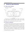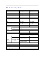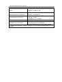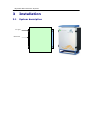
1
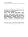
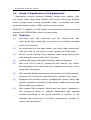
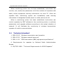
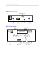
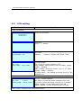
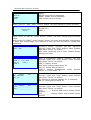
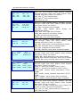
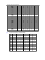
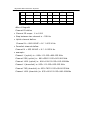
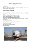
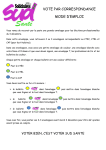
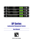
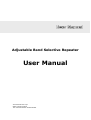
Adjustable Band Selective Repeater
User Manual
SoroushTelecom Corp.
Data Communication
Tell: 02122737305 02122736415
Adjustable Band Selective Repeater
1
General
1.1
Overview
In GSM mobile communication system, limited by the coverage of
base station or by geographic environment, the transmission of signals
may be influenced in shadow or semi-shadow in some areas, generally
referred to as blind area or semi-blind area, bringing serious impact on
voice quality or even causing failure to normal communication. To solve
this problem, apart from adding more base stations, the deployment of
mobile communication repeater, characterized by quick expansion of
coverage and reduction of cost, shall be an ideal cost-effective choice of
high efficiency.
Wireless transmission repeater of GSM mobile communications is an
important tool to expand network coverage, enhance network capacity,
reduce
network
cost
and
realize
network
optimization.
Wireless
transmission repeater of GSM mobile communications is meant to
amplify communication signal, extend network coverage, to improve
communication quality by amplifying some weak received signal and
expanding the signal coverage and to distribute traffic load in various
base stations with efficiency.
In the course of GSM network optimization, wireless transmission
repeater of GSM mobile communications offers a wide variety of
application, and has become an indispensable part of network system. In
some areas, such as satellite cities of some large cities, remote
residential areas, countries and towns or other blind areas or shadow
areas formed due to the natural or human obstacles (such as high
mountains, large buildings, tunnels or underground stores), optical fiber
transmission repeater of GSM mobile communications shall be the most
economical and reasonable solution to the effective coverage of these
Adjustable Band Selective Repeater
networks since these areas are demanding a greater coverage rather
than capacity.
Wireless transmission repeater of GSM mobile communications is
cheap with easy installation. It will greatly reduce the investment in
equipment and running cost to expand the network by optical fiber
transmission
repeater.
The
outdoor
cabinet
design
enables
the
equipment to work under severe conditions in the open air and saves a
lot of operating cost by working without establishment of machine room,
air conditioner or large-scale power supply.
PULSE GX** wireless
communication
transmission repeater integrated with wireless
technology
and
excellent
performances,
provides
operators with multiple solutions that can save the investment in
equipment and running maintenance cost without lowering the network
quality. As a supplement to base stations, the system can be easily
expanded to the blind areas that need covering to solve the problem of
coverage.
By
using
PULSE
GSM
repeater
of GSM mobile
communications, the surplus capacity of networks can be re-planned or
re-arranged so that the resources of networks will be used to their
maximum. The application of repeater shall attract more traffic load with
its short cycles, immediate returned profits, easy installation and savings
of network resources and expand the network coverage with low cost to
make up for the insufficient coverage of system base station. It is a good
solution to optimize network with wireless transmission repeater in
networks.
Adjustable Band Selective Repeater
1.2
Scope of Application of the Equipment
Applicable to airport, stations, highway, railway lines, subway, light
rail, tourist areas, large-scale industry and mining enterprises, satellite
cities of large cities, remote residential areas, countryside and blind
areas and shadow areas of GSM mobile communications.
PULSE GX** repeater of GSM mobile communications mainly serves the
operators of GSM900MHz mobile communication
1.3
Features
(1)
Use filter with high selectivity and low insertion-loss and
multi-grade filter technology to enhance the isolation between
uplink and downlink.
(2)
No interference to the base station and other radio equipments
with low noise for the system, proper linearity and high power.
(3)
Ensure normal working of the repeater under tough environment
with automatic level control (ALC) function.
(4)
Modularized design facilitates assembly and maintenance.
(5)
With local LCD or local PC, technicians can monitor, set, modify
the parameters of all the modules of repeaters and easily collect
equipment information.
(6)
With wireless digital transmission and remote monitoring system,
operator can monitor and maintenance for network more easily.
(7)
Equipped with perfect network management system (NMS) and
friendly operation interface, provide highly reliable operation and
failure treatment capability.
(8)
With Hwatel NMS software, technicians can control repeaters in
the monitoring center or optimize parameters and upgrade
software according to the actual situation of network. It will
facilitate the monitoring of wireless transmission repeater of
mobile communications.
Adjustable Band Selective Repeater
When monitoring center has not been established, technicians can
monitor, set, modify the parameters of all the modules of repeaters and
easily collect equipment warning information via local PC. Once the
repeater fails, monitoring system can immediately send warning
information to designated mobile phone or cable phones at will.
When a monitoring center has been established, technicians can
control repeaters by OMT software in the monitoring center or optimize
parameters and upgrade software according to the actual situation of
network. It will facilitate the monitoring of wireless transmission
repeater of mobile communications.
1.4
Technical standard
1. GSM 05.05 “Wireless transmission and reception
2. GSM 03.30 “Wireless network planning”
3. GSM 11.20 “GSM base station (BBS) equipment specifications”
4. Requirements for repeater by National Radio Administration
Bureau
5. YD/T952-1998 “ Technical Requirements for 900M Repeater”
Adjustable Band Selective Repeater
2
Technical specification
2.1.1 Major blocks diagram
Components of repeater
The equipment consists of duplexers, uplink filters, downlink filters,
uplink band selective amplifying module, downlink band selective
amplifying module, monitoring elements and power elements.
2.1.2 Theory of Operation
The downlink signal received by the donor antenna of the base station
shall be sent to a band selective filter via duplexer to be filtered and to
be amplified by the downlink band selective amplifier to a proper level.
The coverage antenna via a duplexer shall emit the downlink signal.
Similarly, for uplink, the signal received by the re-transmission antenna
shall have its level adjusted to a regulated level by a uplink band
selective amplifier after it is filtered. The donor antenna will emit it after
it is filtered and sent to the duplexer.
Adjustable Band Selective Repeater
2.2
Technical Specification
Item
Up Link
Down Link
Frequency range
890-915MHz
935-960MHz
Max. Output Power
33dBm
33/37/40/43 dBm
Max. Gain
90±3 dB
95±3 dB
Gain step
1 db
Gain adjust scope
31 dB
Adjustable ( Each Step
Band width
25 K)
ALC
0f
<=2 dB
f0<=2 dB
Passband Ripple
No bigger 3 dB
No bigger 3 dB
Frequency Error
±5X10⁻⁸
±5X10⁻⁸
Gain Adjustment Range
No less 30dB
No less 30dB
Gain
-10 dB
±1.0dB
Adjustmen
-20 dB
±1.0dB
t Error
-30 dB
±1.5dB
Gain Adjustment Step
1 dB / Step
1 dB / Step
Noise Figure
<=4 dB
<=4 dB
Spurious emission
Third-order
In Work band
inter-modu
Out band (offset
lation
from work band
distortion
edge 1MHZ)
9KHz-1GHz: <=-36dBm/30KHz
1GHz-12.75GHz: <=-30dBm/30KHz
<=-45dBc/30KHz
9KHz-1GHz:
<=-36dBm/30KHz
1-12.75GHz:
<=-30dBm/30KHz
System Time Delay
< 5 us
VSWR
< 1.4:1
In/Output Impedance (Ω)
50W
In/Output Connector
N-F
Working Voltage
-48V DC or 220V AC
<=-50dBc/30KHz
Adjustable Band Selective Repeater
Requirement
for
technical
safety
Requirement
In accordance with relevant regulations in the
standard of GB4793-84
for
electromagnetic compatibility
In accordance with relevant regulations in the
standard of GB6833-87
Temperature: -25 ˚c ~ 55˚c
Humidity: ≤95%
Air pressure: 70~ 106kPa
Dimension(W x D x H)
360 x 168 x 420mm
LCD and keyboard on Front panel
Management and control
Local computer through RS232
Remote management via GSM SMS channel
* detail tech parameter should reference to Test Report accomplished with its
repeater
Environmental Conditions
Adjustable Band Selective Repeater
3
Installation
3.1
System description
Fix part
Heat sink
Adjustable Band Selective Repeater
3.1.1 Structure and Internal module
3.1.1.1
Power Amplifier
3.1.1.2
LNA Module
3.1.1.3
Filter
3.1.1.4
Duplexer
3.1.1.5
Channel/Band/Frequency Selective
3.1.1.6
GSM Modem
3.1.1.7
Control Unit
3.1.1.8
LCD Panel
Adjustable Band Selective Repeater
3.1.2 Bottom panel
battery
MODEM Antenna
BS
MS
AC220V
GND
Power
Supply
Donor
Antenna
Coverage
Antenna
Ground
3.1.3 Front panel
LCD
Alarm
ON
OFF
GSM900
RF REPEATERS
POWER
Power
Reset
Enter
Shift
RS232
:Up
:
Down
Control Key
:
Right
Adjustable Band Selective Repeater
3.2
LCD setting
LCD
Explain
Power On display
Power On Welcome
PULSE GX **
RF Repeaters
Self test:
A/D1 ----- passed
Test A/D1.. OK
Self test:
Modem ---- passed, if failure will show “Fail”
Test MODEM .. OK
LOOK
DV_27.0V
UPP_28dBm
P1.0
->
DNP_37dBm
Show status:
DV_27.0V:DC power voltage is 27V
UPP_28dBm: Uplink Power now is 28 dBm, (range :
0dBm---33dBm)
DNP_37dBm: Downlink Power now is 37 dBm,:
(range : 0dBm---43dBm)
If there alarm , will display at below, such as “DV
WRONG” etc …
Press “Down” keyboard will show below
LOOK
AC_220V
UPGP_090dB
P1.1 ->
I_02.0A
DNGP_095dB
Item 1.1:Show status:
AC_220V: current AC power voltage is 220 Volt
I_02.0A: current AC power current is 2.0 ampere
UPGP_090dB: current uplink gain is 90 dB
DNGP _095dB: current downlink gain is 95 dB
Press “Down” keyboard will show below menu
Adjustable Band Selective Repeater
<SETUP
SETUP ->
LOOK
VER
P0
->
MENU:
SETUP: setup device parameter
LOOK: display device parameter
VER: display device version
When cursor on “VER”, press “Return” button, will show software version as below
Version information:
PULSE GX**
VER1.0
PULSE GX**
VER1.0
When cursor on “SETUP”, press “Return” button, will enter setting page and show
below
When cursor on “LOOK”, press “Return” button, will enter looking page, looking page
is same with setting page, only different is can just look and can nor modify any
parameter
Password setting: operator can edit password
through “right” and “shift” button; when finished
edit press “return” to confirm
KEY_0000: password now is 0000, Default factory
password is 0000
KEY_ 0000
<SETUP
P2.1
VER_2
FAC_ 0000
FIX_41
COM_2
VER_2
->
<SETUP
ID _ 00000000
SN _ FF
->
P2.2
<SETUP
P2.3 ->
CTel _ _ _ _ _ _ _ _ _ _ _ _
JTel _ _ _ _ _ _ _ _ _ _ _ _
Item 2.1:Parameter setting: operator can edit
through “right” and “shift” button; when finished
edit press “return” to confirm
VER_2: setting Version
FAC_0000: setting manufactory ID
FIX_41: setting device type ID
COM_2: setting management mode; Remote
mode: ”2”;Local mode: ”5”
Item 2.2:Parameter setting: operator can edit
through “right” and “shift” button; when finished
edit press “return” to confirm
ID_00000000: Setting repeater ID , 8 character
SN_FF: setting device serial ID
Item 2.3:Parameter setting: operator can edit
through “right” and “shift” button; when finished
edit press “return” to confirm
CTel________: Setting NMS center Mobile phone
number
JTel________: Setting Alarm report Mobile phone
number
Adjustable Band Selective Repeater
<SETUP
P2.4 ->
CH1 _ ON
CH2 _ ON
CH3 _ OFF
CH4 _ OFF
CH5 _ OFF
CH6 _ OFF
<SETUP
P2.5 ->
DVL_ON
L1G_OFF
LNA1 _ ON
LNA2_OFF
GL _ ON
DOOR_ON
<SETUP
P2.6 ->
UPP_ON
DNP_ON
TCH_ON
DLP_ON
<SETUP
UPSW _OFF
CS_OFF
P2.7
DNSW_ON
POWER_ON
<SETUP
UHPA_ 0
UATT_ 00dB
UPH--+05dBm
P2.8 ->
DHPA-1
DATT_ 00dB
DPH--+36dBm
<SETUP
P2.9 ->
CH1_ 055
CH2_ 050
CH3_ 065
CH4_ 060
Item 2.4: work channel enable setting: operator
can edit through “right” and “shift” button; when
finished edit press “return” to confirm
CH1_ON: 1st work channel open
CH2_ON: 2nd work channel open
CH5~CH8: no use
Item 2.5: Alarm Enable setting: operator can edit
through “right” and “shift” button; when finished
edit press “return” to confirm
DVL_ON: Loss power alarm Enable
L1G_OFF: Fiber Optical alarm Enable (for
GV900F-OW family)
LNA1_ON: uplink LNA failure Enable
LNA2_ON: downlink LNA failure Enable
GL_ON: self active alarm Enable
DOOR_ON: door open alarm Enable
Item 2.6: Indicator Enable setting: operator can
edit through “right” and “shift” button; when
finished edit press “return” to confirm
UPP_ON: uplink power overload Indicator enable
DNP_ON: downlink power overload enable
TCH_ON: temperature alarm Enable
DLP-ON: downlink input power threshold enable
Item 2.7: Alarm Enable setting: operator can edit
through “right” and “shift” button; when finished
edit press “return” to confirm
UPSW_ON: uplink stationary wave alarm enable
DNSW_ON: downlink stationary wave alarm enable
POWER_ON: power modular failure alarm enable
Item 2.8: Alarm Enable setting: operator can edit
through “right” and “shift” button; when finished
edit press “return” to confirm
UHPA_0: uplink PA enable(0 close/1 open)
DHPA_1: downlink PA enable(0 close/1 open)
UATT_00dB: setting uplink attenuation ATT(0
31dB)
DATT_99dB: setting downlink attenuation ATT(0
31dB)
UPH_+05dBm: uplink power upper threshold
DPH_+36dBm: downlink power upper threshold
Item 2.9: Work band setting: operator can edit
through “right” and “shift” button; when finished
edit press “return” to confirm
CH1_050: For ABS, setting start work channel ID.
(scope 1~1000, reference to appendix)
CH2_055: For ABS, setting end work channel ID.
CH3_060: No use
Adjustable Band Selective Repeater
CH4_065: No use
<SETUP
P2.10
CH5_ 000
CH6_ 000
CH7_ 000
CH8_ 000
->
<SETUP
P2.11 ->
UPALC_ 00dB DNALC-00dB
ATTU_ 00dB ATTD_ 00dB
UGP_090dB
DGP_095dB
<SETUP
KEY _ 0000
3.3
P2.12 ->
Item 2.10: Work channel setting: operator can edit
through “right” and “shift” button; when finished
edit press “return” to confirm
CH5_000: No use
CH6_000: No use
CH7_000: No use
CH8_000: No use
Item 2.11: parameter setting: operator can edit
through “right” and “shift” button; when finished
edit press “return” to confirm
UPALC_00dB: uplink ALC value (no use for ABS)
DNALC_00dB: downlink ALC value (no use for ABS)
ATTU_00dB: setting uplink attenuation (0~31dB)
(no use for ABS)
ATTD_00dB: setting downlink attenuation (0
31dB) (no use for ABS)
UGP_90dB: setting uplink MAX gain
DGP_95dB: setting downlink MAX gain
Item 2.12: password setting: operator can edit
through “right” and “shift” button; when finished
edit press “return” to confirm
KEY_0000: setting pass word, Default factory pass
word: 0000
Preparations before Installation of the Equipment
Following jobs should be done before installation of equipment:
§ Site reconnaissance and test of electromagnetic environment
§ Selection of plan for coverage, determination of construction plan
The site reconnaissance and test of electromagnetic environment
shall be basis for design and installation of the constructions. The
contents include the position of the donor antenna and its field intensity,
areas under coverage and landform, determination of the fixing position
of the antenna and plan for cable laying, and the design and installation
of grounding system.
(1)
Installation of antenna
1) Donor antenna must be carefully adjusted so that it will face the
base station in an exact way.
2) Coverage antenna must keep a proper isolation degree with donor
Adjustable Band Selective Repeater
antenna while its coverage must be ensured. For isolation degree, the
greater, the better.
(2)
Selection of band
Set to corresponding frequencies by using the monitoring and control
software of the repeater.
(3)
Field intensity test and level adjustment.
Level adjustment is important in the opening of wireless transmission
repeater construction, especially for downlink passage. First, test field
intensity of the signal of the base by donor antenna and then adjust the
uplink and downlink gains according to the field intensity of the signal so
that the downlink output shall meet the requirements of coverage.
Meanwhile, adjust corresponding uplink and downlink gains.
(4)
Sealing of joints of feed lines:
it is suggested that it should be powered up first and test the level to
see if it is normal before the sealing of joints of feed line of antenna.
Clean the joint’s inner part before installation of it, check and see if the
length of cable core and their left or right position are correct and then
fix them. Check if the joint is fastened before sealing.
(5)
Lightning protections
The location of wireless transmission repeater is usually in high
buildings or at the top of mountain and is connected to the antenna by
feed line. Thus it should have reliable lightning protection. The lightning
protections of wireless transmission repeater include the followings:
§ Cases, antenna bases and cables must be reliably grounded.
§ Inlet power cables must be protected against lightning.
§ The lightning protection of antenna.
(6)
Grounding of Equipment
Peel off the plastic skin of the feed line with special tools according to
the requirements of the process and leave a 6 to 7cm cut. Do not hurt
the inner ripple copper tube. Fasten it with copper braided tape to ensure
Adjustable Band Selective Repeater
that it is closely fastened with ripple copper sheet. Seal it with tape or
clay and fasten the other end firmly to ground. Fixing screws or nuts
must receive anti-rust treatment.
3.4
Installation and Opening of Equipment
Open the package and check the merchandise according to packing
list. Consult with construction units and determine the position and
height of the antenna pole, ways of feed line laying and fixing, position
for installation of the equipment and burying of 220V power and ground
cables according to the position for installation determined in the report
and field intensity tested on site. Then install and debug in accordance
with the following steps:
1. Before installation of the equipment, set up the donor antenna in
the selected position for donor antenna, check if the signal received by
donor antenna and the signal amplitude agree with design plan. Adjust
the direction and angle of the antenna to achieve a maximum value of
amplitude of the signal from base station. Then, fix the donor antenna.
2. Determine the brief direction of the coverage antenna according to
the plan and install the antenna. The way of polarization is usually
vertical. The gains of vertical polarization is superior to 2-3dB, however,
the vertical polarization has a small angle and is too much exposed so
the antenna must be fixed. In addition, the way of installation of the
dipole antenna and reflector under various polarizations shall be
determined in accordance with installation instructions for the antenna.
3. After fixing of the equipment, open it and test the mobile signal
with a mobile phone and adjust the position of the antenna to achieve
best coverage.
4. After the adjustment of antenna, fasten the antenna to avoid
impact of external force. Pay attention to grounding of the equipment.
5. Description of indicators: When the equipment is powered up, red
Adjustable Band Selective Repeater
light will be on indicating that the equipment is in the status of
initialization. The yellow light will blink in regular intervals to indicate
that the system is working normally. After a while, the red light will be
off, indicating that initialization is completed and the system is in
working status. It usually takes 10 seconds when it is under the
condition without modem. If it is connected to wireless modem, it takes
one minute to initialize. Users can operate the equipment with supplied
software after the system has entered normal working condition. Green
light will blink irregularly, indicating that it is working normally.
6. Installation of monitoring and control system (wireless modem)
4
Maintenance
It is unnecessary to shut down the equipment without special need
once the equipment is put to use. Therefore, the equipment must be
used in ventilated and clean environment, avoiding dust from entering
the equipment, consequently causing damage. The equipment can work
soundly on the condition of temperature of -25˚C ~ +55˚C and humidity
of 95%.The equipment must be shut down immediately for maintenance
once abnormities occur (such as noise from module increases or odor
appears). Check if the antenna fails to receive signals due to the change
of angle when the signals cannot be received or received poorly while the
equipment is found to work with normality. Adjust antenna and re-fix it
when it is found with changed angle.
When the equipments are working normally, do not touch the joints
between equipment if not necessary so as to prevent joints from getting
loosened or improperly contacted. When the equipment fails, user must
turn it off and notify our company. It is not allowed to take apart the
joints between the equipment or to turn on the equipment, to avoid
accident.
Adjustable Band Selective Repeater
5
Cautions
The products of our company have been tested and aged before
delivery so as to ensure quality.
The products are sealed upon delivery and no units or individuals are
allowed to unseal them without the authorization of our company. Our
company shall not be liable for any consequences caused due to the
unauthorized start of the product.
Check all the attached accessories by packing list upon reception of
the equipment of our company. Contact the supplier in time for any
shortage.
Our company owns the property right of our products which is
protected by State law. No units or individuals are allowed to copy them.
Our company shall investigate any of these actions for their legal
responsibilities and reserves the right to claim for economic losses duly
suffered.
Appendix
(1)
Attenuation DIP setting
Attenuation
value
1dB
2dB
3dB
4dB
5dB
6dB
7dB
8dB
1
0
1
0
1
0
1
0
1
DIP switch
2
3
1
1
0
1
0
1
1
0
1
0
0
0
0
0
1
1
ON=”1”
4
1
1
1
1
1
1
1
0
5
1
1
1
1
1
1
1
1
Adjustable Band Selective Repeater
9dB
10dB
11dB
12dB
13dB
14dB
15dB
16dB
17dB
18dB
19dB
20dB
21dB
22dB
23dB
24dB
25dB
26dB
27dB
28dB
29dB
30dB
31dB
(2)
0
1
0
1
0
1
0
1
0
1
0
1
0
1
0
1
0
1
0
1
0
1
0
1
0
0
1
1
0
0
1
1
0
0
1
1
0
0
1
1
0
0
1
1
0
0
1
1
1
0
0
0
0
1
1
1
1
0
0
0
0
1
1
1
1
0
0
0
0
0
0
0
0
0
0
0
1
1
1
1
1
1
1
1
0
0
0
0
0
0
0
0
1
1
1
1
1
1
1
0
0
0
0
0
0
0
0
0
0
0
0
0
0
0
0
Power Watt to dBm exchange table
DBm
watt
dBm
watt
dBm
watt
dBm
watt
0
0.001
16
0.04
31
1.28
46
40
1
0.00125
17
0.048
32
1.6
47
51.2
3
0.002
18
0.064
33
2
48
64
4
0.0025
19
0.08
34
2.56
49
80
5
0.003
20
0.1
35
3.2
50
100
6
0.004
21
0.128
36
4
51
128
7
0.005
22
0.16
37
5.12
52
160
8
0.006
23
0.2
38
6.4
53
200
9
0.008
24
0.256
39
8
54
256
10
0.01
25
0.32
40
10
55
320
11
0.012
26
0.4
41
12.8
56
400
Adjustable Band Selective Repeater
12
0.016
27
0.512
42
16
57
512
13
0.02
28
0.64
43
20
58
640
14
0.024
29
0.8
44
25.6
59
800
15
0.032
30
1
45
32
60
1000
dBm=10logmW
Channel ID define
§ Channel ID scope : 1 to 1000
§ Step between two channel is : 25K Hz
§ Uplink channel define:
Channel N = 890.000HZ + N * 0.025 M Hz
§ Downlink channel define:
Channel M = 935.000HZ + M * 0.025 M Hz
§ example:
Channel 1 (uplink) is : 890+1*0.025=890.025 MHz
Channel 556 (uplink) is : 890+556*0.025=903.900 MHz
Channel 1000 (uplink) is : 890+1000*0.025=915.000MHz
Channel 1 (downlink) is: 935+1*0.025=935.025 MHz
Channel 785 (downlink) is: 935+785*0.025=954.625 MHz
Channel 1000 (downlink) is: 935+1000*0.025=960.000MHz