1
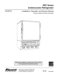
REF Series
Undercounter Refrigerator
Order parts online
www.follettice.com
Installation, Operation and Service Manual
Before service number B59000
Following installation, please forward this manual
to the appropriate operations person.
Cool Ideas For Ice Management
801 Church Lane • PO Box D, Easton, PA 18044, USA
Toll free (800) 523-9361 • (888) 2-FOLLETT
(610) 252-7301 • Fax (610) 250-0696 • www.follettice.com
U® L
C
U® L
00104109R09
Cool Ideas For Ice Management
Follett Corporation
Equipment Return Policy
Follett equipment may be returned for credit under the following conditions:
1. The equipment is new and unused.
2. A return authorization number has been issued by customer service within 30 days after shipment.
3. Follett receives the equipment at the factory in Easton, PA within 30 days after issuance of the return authorization number.
4. The equipment must be returned in Follett packaging. If the packaging has been damaged or discarded, Follett will forward,
at the customer’s expense, new packaging.
Note:
Return freight charges are the responsibility of the customer. If equipment is returned and is damaged because of
improper packaging, Follett Corporation will not be held responsible.
Credit will be issued when:
The equipment has been inspected by Follett and deemed suitable to be returned to stock.
Note:
A 15% restocking charge will be deducted from the credit. If the cost to return the product to stock exceeds 15%, the
actual cost will be deducted.
2
Table of contents
Welcome to Follett. . . . . . . . . . . . . . . . . . . . . . . . . . . . . . . . . . . . . . . . . . 4
Before you begin . . . . . . . . . . . . . . . . . . . . . . . . . . . . . . . . . . . . . . . . 4
Specifications . . . . . . . . . . . . . . . . . . . . . . . . . . . . . . . . . . . . . . . . . . . . . 4
Installation procedures . . . . . . . . . . . . . . . . . . . . . . . . . . . . . . . . . . . . . . 5
Stabilizer adjustment . . . . . . . . . . . . . . . . . . . . . . . . . . . . . . . . . . . . . 5
Sealing the unit. . . . . . . . . . . . . . . . . . . . . . . . . . . . . . . . . . . . . . . . . . 5
Shelving adjustment . . . . . . . . . . . . . . . . . . . . . . . . . . . . . . . . . . . . . .5
Reversing door. . . . . . . . . . . . . . . . . . . . . . . . . . . . . . . . . . . . . . . . . . 5
Changing the temperature set point . . . . . . . . . . . . . . . . . . . . . . . . . 6
Operation . . . . . . . . . . . . . . . . . . . . . . . . . . . . . . . . . . . . . . . . . . . . . . . . .
How the refrigerator works . . . . . . . . . . . . . . . . . . . . . . . . . . . . . . . .
Temperature control . . . . . . . . . . . . . . . . . . . . . . . . . . . . . . . . . . . . .
Defrosting . . . . . . . . . . . . . . . . . . . . . . . . . . . . . . . . . . . . . . . . . . . . .
Cleaning. . . . . . . . . . . . . . . . . . . . . . . . . . . . . . . . . . . . . . . . . . . . . . .
7
7
7
7
7
Service information . . . . . . . . . . . . . . . . . . . . . . . . . . . . . . . . . . . . . . . . . 8
Latch adjustment . . . . . . . . . . . . . . . . . . . . . . . . . . . . . . . . . . . . . . . . 8
Gasket replacement . . . . . . . . . . . . . . . . . . . . . . . . . . . . . . . . . . . . . 8
Slide-out compressor tray . . . . . . . . . . . . . . . . . . . . . . . . . . . . . . . . . 8
Wiring diagram . . . . . . . . . . . . . . . . . . . . . . . . . . . . . . . . . . . . . . . . . 8
Refrigeration system diagram . . . . . . . . . . . . . . . . . . . . . . . . . . . . . . 9
Troubleshooting guide . . . . . . . . . . . . . . . . . . . . . . . . . . . . . . . . . . . 10
Accessory information . . . . . . . . . . . . . . . . . . . . . . . . . . . . . . . . . . . . .11
Temperature alarm. . . . . . . . . . . . . . . . . . . . . . . . . . . . . . . . . . . . . . 11
Pyxis . . . . . . . . . . . . . . . . . . . . . . . . . . . . . . . . . . . . . . . . . . . . . . . . 12
Replacement parts . . . . . . . . . . . . . . . . . . . . . . . . . . . . . . . . . . . . . . . . 13
3
Welcome to Follett
Follett equipment enjoys a well-deserved reputation for excellent performance, long-term reliability and
outstanding after-the-sale support. To ensure that this product delivers that same degree of service, we ask that
you take a moment to review this manual before beginning the installation. Should you have any questions or
require technical help at any point, please call our technical service group at (800) 523-9361, (888) 2-FOLLETT
or (610) 252-7301.
Before you begin
After uncrating and removing all packing material, inspect the equipment for concealed shipping damage. If
damage is found, notify the shipper immediately and contact Follett Corporation so that we can help in the filing of
a claim, if necessary.
Specifications
Series specifications
REF4-ADA
REF5
31.5" height
34.5" height
fits below 34" high ADA-compatible counter
fits below standard 36" high counter
4.0 cu ft capacity
4.8 cu ft capacity
Electrical specifications
115V, 60Hz, 1 phase
Full load amps: 8.0
Minimum circuit ampacity: 15 amp
Maximum size of branch circuit overcurrent device: 15 amp
Refrigeration specifications
Refrigerant – R404A
Charge size – 8 oz
Maximum design pressures:
High side – 375psi
Low side – 174psi
Installation specifications
Ambient temperature must not exceed 100°F (38°C).
The front louvered panel must be kept free of any cabinet trim or obstructions to ensure proper ventilation of the
refrigeration system.
Important cautions
Equipment must be wired according to local and NEC codes.
Always disconnect power before servicing refrigerator.
4
Installation
Leveling the refrigerator
Internal stabilizing legs are provided to level the refrigerator in its final location. These legs are retracted for
shipping. To allow the refrigerator to slide easily during installation the stabilizing legs can be extended to clear
the bottom of the refrigerator panels.
To access the stabilizing legs, remove the lower front panel. Turn the legs clockwise to lower and
counterclockwise to raise.
Shelving adjustment
The epoxy-coated wire shelves may be adjusted in .5" increments.
1. Remove shelf.
2. Remove each shelf bracket by applying pressure and lifting bottom tab up and out of pilaster.
3. Insert each shelf bracket in new location by inserting top curved tab and applying pressure while inserting
lower tab.
4. Reinsert shelf.
Reversing the door swing – optional
1. Remove screws and latch from refrigerator cabinet. (Fig. 1.1).
2. Use flat screwdriver to carefully remove (do not scratch) hinge covers (Fig. 2.1).
3. Support door and remove screws attaching hinge to refrigerator cabinet (Fig. 2.2).
4. Cover hinge screw holes with screw hole plugs removed from opposite side.
5. Reverse door and reinstall hinge screws.
6. Reinstall latch on opposite side.
7. Remove screws and handle from door (Fig. 3.1).
8. Rotate handle (Fig. 3.2).
9. Reinstall handle screws (application of 242 blue Loctite® to handle screws recommended).
Fig. 1
Fig. 2
Fig. 3
1
1
2
1
2
1
2
5
Changing the temperature set point
Follett sets the temperature controller to a 38˚F set point. This set point may not deliver the temperature range
desired for your specific application. For example, some medicine manufacturers suggest a storage temperature
range of 36˚ to 46˚F. Therefore, we have provided you with the ability to easily change the set point to meet your
specific needs. The changes can be made on the temperature controller located on the bottom left corner of the
unit front.
1. Press SET. SP1 will display (Fig. 4.1).
2. Press SET. Current set point will display (Fig. 4.2).
3. Press up or down on ADJUST to change the set point to
desired temperature (Fig. 4.3).
4. Press SET (Fig. 4.4). The characters on the display will
disappear for a moment (Fig. 4.5) and then display the current
temperature (Fig. 4.6). The new set point is now accepted.
Note: See Fig. 5 for examples of temperature ranges
by set point.
Fig. 4
1 OUTPUT
°F
ADJUST
SET
1
1 OUTPUT
°F
ADJUST
SET
2
1 OUTPUT
°F
Fig. 5 – Examples of temperature ranges by set point
3
Set point
temperature
Cut-in
Cut-out
Normal
display range
38˚
39˚
40˚
41˚
42˚
43˚
44˚
45˚
46˚
38˚
39˚
40˚
41˚
42˚
43˚
44˚
45˚
46˚
34˚
35˚
36˚
37˚
38˚
39˚
40˚
41˚
42˚
32˚ - 38˚
33˚ - 39˚
34˚ - 40˚
35˚ - 41˚
36˚ - 42˚
37˚ - 43˚
38˚ - 44˚
39˚ - 45˚
40˚ - 46˚
ADJUST
SET
1 OUTPUT
°F
ADJUST
SET
4
5
1 OUTPUT
°F
ADJUST
SET
6
All set points have a built-in 3˚ differential. The 3˚ differential means that with a 38˚F set point, for example, the
compressor will turn on at 38˚F and run through 37˚, 36˚, and 35˚F (-3˚) before turning off when it reaches 34˚F.
Because there is still refrigerant in the system, there can be an additional 1˚ - 1.5˚ of “drift” down in temperature
after the compressor shuts off. The temperature may momentarily display as low as 32˚F (32.9˚F and below
rounds down to 32˚F) before beginning to rise again.
6
Operation
How the refrigerator works
The temperature control board and probe indicate when the refrigeration system is required to turn on and off. The
probe signals the controller to turn the refrigeration system on when the interior cabinet temperature rises to the
controller set point. The normally open contacts of the controller close, energizing the coil of the control relay.
Then the normally open contacts of the relay close, energizing the evaporator and condenser fan motors and the
compressor. The compressor uses a current-style starting relay and a starting capacitor to start the compressor
motor. The refrigeration system then removes heat from the cabinet interior and rejects it to the surrounding room
air. When the cabinet interior temperature falls by 3°F (controller will indicate 4°F), see explanation at the bottom
of page 6, the probe signals the controller to turn the refrigeration system off. The controller contacts reopen, deenergizing the control relay coil. The relay contacts reopen, which de-energizes the evaporator and condenser fan
motors, and the compressor. Any accumulated frost on the evaporator coils melts during the off cycle. The
condensate drains to the plastic drain pan mounted above the condensing unit where it is evaporated by the heat
from the condensing unit.
Temperature control
The temperature control system is preset by the factory to maintain a cabinet temperature of 35°F - 38°F. If
desired the cut in temperature of the controller can be raised to as high as 50°F by following the instructions on
page 6 for changing the temperature set point. The 3°F cut out differential will be maintained regardless of the
controller set point.
Defrosting
REF Series undercounter refrigerators do not require manual defrosting. The unit cooler defrosts automatically
when the condensing unit is in the OFF cycle.
Cleaning
!
Use only non-chlorine-based cleaners. Cleaners containing chlorine can cause staining and pitting of the
stainless steel.
Interior – Using a sponge or soft cloth, clean unit with a non-abrasive, non-chlorinated, all-purpose detergent.
Exterior – Wipe exterior with a soft cloth in the direction of grain as needed. Stainless steel polish may be used to
enhance the finish of the unit.
Annual cleaning
Removal of dust and other particulates from air intake areas and the condenser is important for proper operation.
Some environments with large amounts of dust may require
Fig. 6
more frequent cleaning.
1. Disconnect power to unit by turning switch on the lower
front panel to the OFF position, switching circuit breaker to
OFF position, and removing power cord from receptacle.
2. Remove lower front and rear panels (Fig. 6.1).
Note: Front louvered panel may be removed for more
frequent cleaning of the condenser as needed
3. Remove drain pan (Fig. 6.2).
4. Clean drain pan with a non-abrasive, non-chlorinated allpurpose detergent.
5. Reinstall drain pan.
6. Use a vacuum cleaner with brush attachment to clean
condenser through lower front panel and compressor
motor and related parts through lower rear panel.
7. Reinstall lower rear and lower front panels.
7
2
1
Service
Latch adjustment
Fig. 7
To adjust for proper latch engagement
1. Loosen striker plate mounting screws (Fig. 7.1).
2. Move striker plate up or down as required and tighten screws.
3. Test operation of latch.
To adjust for proper gasket seal
1. Loosen striker depth adjustment screw (Fig. 7.2).
2. Adjust stop in or out and tighten screws.
3. Test operation of latch.
Door gasket replacement
1. Remove existing gasket from mounting track. Verify mounting
track is free of any remaining gasket material.
2. Align new gasket with mounting track and press firmly in place.
3. Open and close door, checking for proper gasket seal without
pinching against refrigerator. Adjust latch and or striker as
necessary for proper door closure.
1
2
Fig. 8
Slide-out compressor tray
Follett's slide-out compressor tray allows technicians to partially slide
the condensing unit from the refrigerator back without cutting
refrigerant lines.
a
ylvani
Easto
n Penns NO
PART
S
VOLT
FULL
OR
RESS
AMPS
R COMP
LOAD
MOTO
SIDE
ANT
HIGH
IGER
SURE
TY
PRES
REFR
N
LE
SING E
PHAS
OZ
HZ
D
ECTE
GE
ION L NO
ORATSERIA
CORP
L
MODE
DESIG
PSIG
Y PROTCHAR
MALL
IN
SIDE
THER
MADE
USA
THE
LOW
UL
NS
F
R
UL
C
R
AMPS
AMPS
AMPACI
CIRCUIT
BRANCH
MIN.
SIZE
FUSE
CIRCUIT
BRANCH
MAX.
208264
No.
Modulet
Produc No.
1. Remove the rear panel (Fig. 8.1)
2. Remove the two screws and spacers securing the condensate
pan, and set the pan aside (Fig. 8.2).
3. Remove the two bolts securing the condensing unit to the
refrigerator base (Fig 8.3).
4. Gently slide the condensing unit out (Fig 8.4).
Service
3
Note: Do not put undue strain on the refrigerant lines
4
Wiring diagram
L2
2
1
NEUTRAL
WHITE
CONDENSING UNIT
WHITE
R1
RELAY
WHITE
WHITE
BLUE
CONTROLLER
EVAP.
FAN
CAP.
START
RELAY
ND.
N
120 VAC
C
COMP
Note 1: Highlighted area on wiring diagram
indicates jumper included on refrigerators
with service numbers:
OVER
LOAD
BLACK
ON/OFF
SWITCH
BLACK
CK
BLACK
Note 1
BLUE
R1
RELAY
Service numbers B50486 to B57373 for
model REF5
Service numbers B50479 to B57369 for
model REF4-ADA
R1
RELAY
BLACK
L1
HOT
BLACK
BLACK
8
Refrigeration system
The REF Series refrigeration system is designed to give many years of trouble-free service. Except for routine
cleaning of the air-cooled condenser and related parts, the refrigeration system requires no service or
maintenance. The system uses a capillary tube and is critically charged. Access fittings are provided for ease of
service. However, the connection of refrigeration service hoses to the fittings will almost invariably result in a
significant change in the system charge. This change can adversely affect the performance of your refrigerator.
Therefore, Follett recommends that if hoses are ever connected to the refrigeration system for service, the
refrigerant should be recovered, the system evacuated, and recharged by weighing in the correct refrigerant
charge.
Note: Do not charge the system by pressures.
Checking refrigeration system pressures
1. Remove the rear access panel (Fig. 8).
2. Turn the power switch to the on position.
3. Following the instructions on page 6 verify that the temperature controller is set to the original factory cut-in
setting of 38˚F.
4 Allow the refrigerator to operate and stabilize at least 30 minutes, verifying the cut-out temperature is being
reached.
5. Connect refrigerant hoses to access fittings and measure air temperature at condensor intake grille.
6. Verify correct pressures with the temperature chart below.
Condensor inlet air temperature
Discharge pressure
Suction pressure
70
198
25
80
230
31
90
270
38
100
311
46
Troubleshoot refrigeration system as needed.
Note: Do not attempt to obtain correct refrigeration pressures by adjusting the system charge.
Refrigeration system diagram
EVAPORATOR
CAPILLARY TUBE
HIGH PRESSURE VAPOR
LOW SIDE
SERVICE PORT
COMPRESSOR
CONDENSER
HIGH PRESSURE LIQUID
LOW PRESSURE LIQUID
FILTER-DRIER
HIGH SIDE
SERVICE PORT
9
LOW PRESSURE VAPOR
Refrigerator troubleshooting guide
Before calling for service
1. Check that unit is plugged in.
2. Test outlet with another appliance to verify power.
Symptom
Possible cause
Solution
Refrigerator does not operate
(no components run)
1. Power switch faulty or in OFF
position; loose connection.
2. Refrigerator not plugged in.
3. No power to cord.
4. Temp controller not energizing
control relay.
5. Defective control relay.
6. Probe not sensing cut in
temperature.
1. Condensing unit power cord not
plugged in to socket.
2. Control relay contacts not closing.
1. Thermal overload open or
defective.
2. Capacitor and/or relay defective.
3. Compressor defective.
1. Evaporator power cord not
plugged in to socket.
2. Control relay contacts not closing.
3. Defective fan motor.
1. Controller not sensing cut off
temperature.
2. Controller keeping control relay
energized.
3. Control relay stuck closed.
1. Condenser or evaporator coil
needs cleaning.
2. Faulty door gasket.
3. Excessively high ambient.
1. Turn power switch to ON position;
check switch and connections.
2. Connect plug.
3. Restore power.
4. Check controller contact terminals for
power. Replace controller if needed.
5. Replace relay.
6. Replace controller and/or probe.
Compressor and condenser
fan do not run.
Compressor does not run.
Evaporator fan motor does not run.
Refrigerator does not shut off.
Refrigerator does not maintain
temperature (all components run).
4. Refrigerant leak.
5. Incorrect refrigerant charge.
6. Plugged capillary tube.
7. Inefficient compressor.
1. Reconnect power cord.
2. Replace relay.
1. Allow to cool or replace.
2. Replace as required.
3. Replace compressor.
1. Reconnect power cord.
2. Replace relay.
3. Replace fan motor.
1. Replace controller and/or probe.
2. Replace controller.
3. Replace control relay.
1. Clean coils as needed.
2. Replace door gasket.
3. Maximum recommended ambient is
100 degrees F.
4. Locate and repair leak.
5. Recover, evacuate and weigh in
correct charge.
6. Replace capillary tube.
7. Consult technical service.
If problems persist after following this basic troubleshooting guide, call Follett’s
technical service group at (800) 523-9361, (888) 2-FOLLETT or (610) 252-7301.
10
Accessories
Temperature alarm
Fig. 9
Before installing alarm
1. Remove supplied 9-volt back-up battery
from packing box.
2. Remove 2 screws from module face and
remove faceplate.
3. Install back-up battery on battery connector.
4. Locate DIP switches on the back of the
faceplate (Fig. 9).
5. Review the factory DIP switch settings
(Fig. 10) and make any changes required to
meet the needs of your specific application.
6. Reinstall faceplate.
Fig. 10
Dip Switch
1
2
OFF (factory default setting)
No alarm delay
Auto reset (alarm stops automatically as
soon as temperature returns to set range)
3&4
3
Audible alarm on
Enables 5 min alarm “snooze”
when reset button is pressed (with 4 on)
ON
45 minute alarm delay
Manual reset of alarm (user must press
RESET button to stop audible alarm even if
temperature has returned to set range)
No audible alarm
Enables 45 min alarm “snooze”
when reset button is pressed (with 4 off)
Fig. 11
Installing alarm
1. Mount alarm in desired location with screws (supplied
by others) through back of housing. Do not place
undue strain on probe cable.
Note: Do not modify length of probe wire. Probe will not
measure temperature correctly if wire length is changed.
2. Plug power cord into 110 outlet.
3. Push center tab of short bottle bracket into top of rear left
pilaster (Fig. 11).
Note: Use longer bottle bracket for REF5 refrigerators
using cut-out upper shelf accessory.
4. Fill bottle with glycerin or other liquid to increase accuracy
of readings by simulating the internal temperature of
medications.
5. Insert bottle into bottle bracket.
11
6. Route probe through hole in refrigerator back and push
probe down through gasketed bottle top.
Fig. 12
Note: Alarm probe must be placed in bottle for
proper system operation. Refer to Fig. 12 if attaching
alarm to central monitoring or central alarm system. A
SPDT 1 amp 24V AC resistive relay is provided for this
connection.
AC
AC
Power
in
Black
White
Sensor
Red
NC
NO
Output
Com
Setting alarm temperatures
1. After the installation is complete, allow 30 minutes
for the system to stabilize to ambient temperature.
2. Calibrate temperature alarm to refrigerator display
a. Press SET until “CAL” is displayed (Fig. 13.1).
b. Press SET again to display “CAL” value (Fig. 13.1).
c. Press top or bottom of ADJUST arrow to show
same temperature as displayed by refrigerator (Fig. 13.2).
3. Set high alarm limit
a. Press SET until “HSP” is displayed (Fig. 13.1).
b. Press SET again to display HSP value (Fig. 13.1).
c. Press top or bottom of ADJUST arrow until desired
HSP value is displayed (Fig. 13.2).
4. Set low alarm limit
a. Press SET until “LSP” is displayed (Fig. 13.1).
b. Press SET again to display LSP value (Fig. 13.1).
c. Press top or bottom of ADJUST arrow until desired
LSP value is displayed (Fig 13.2).
Fig. 13
1
2
Alarm operation facts
The back-up battery will continue to provide alarm protection
during power failure but will alarm ONLY if temperatures go out of
the selected range. During power failure the alarm face will be
dark but temperatures can be read by pressing the RESET
button.
To see the highest or lowest temperature since last reset,
press the button until “HI” or “LOW” appears. To clear log
value, press RESET.
Because the temperature alarm display simulates the true
temperature of stored medications rather than the air temperature
inside the refrigerator, we suggest that
staff refer to the alarm display to log temperatures for JCAHO
compliance.
Pyxis® system interface
The Pyxis-compatible door bracket interfaces with Pyxis’ standard lock box. The bracket must be installed by
Pyxis authorized installing technicians. Contact Pyxis directly at 800-367-9947 for questions relating to Pyxis
system operation.
12
Replacement parts
Condensing unit - Reference #11
Evaporator - Reference #5
13
2
3
10
1
9
8
6
12
7
4
14
Refrigeration
Reference #
1
2
3
4
5
6
7
8
Not shown
Not shown
9
10
11
12
13
Not shown
14
Description
Fan motor, evaporator
Bracket, fan motor
Fan blade
Fan guard
Evaporator (includes parts above)
Filter drier & capillary tube
Compressor
Starting capacitor
Starting relay
Overload protector
Condenser fan motor
Condenser fan blade
Condensing unit
Wiring strain relief
Condenser
Cap, starting capacitor
Drain tube, evaporator (includes clamp)
13
Part #
00104919
00104927
00104935
00104943
00104885
00103267
00104950
00104968
00104976
00104984
00104992
00105007
00105106
00105577
00105619
00105627
00121681
22
19
21
4
23
9
10
7
2
11
1
8
18
3
rear cutaway
17
12
6
13
5
20 24
16
14
Hardware
Reference #
1
Not shown
2
3
4
5
6
7
8
Not shown
9
10
Not shown
11
12
13
14
15
16
Not shown
17
Not shown
15
Description
Door, REF5 (includes gasket)
Door, REF4-ADA (includes gasket)
Latch & striker (includes screws)
Latch screws (each – 3 per latch)
Striker screws (each – 2 per striker)
Hinge (each – 2 required, includes screws)
Hinge screws (each – 6 per hinge)
Strip sealer (set of 4)
Gasket, REF5 (21 5/8" x 21 5/8" door)
Gasket, REF4-ADA (18 5/8" x 21 5/8" door)
Shelves (each)
Pilaster (each)
Thumb screws (set of 8)
Shelf support (snap-in, each)
Lower front panel (includes 00114371 and screws)
Front panel screws (each – 6 per panel)
Rear panel (includes screws)
Rear panel screws (each – 6 per panel)
Condensate tray (includes screws & spacers)
Key
Spacer, condensate pan
Seal, bushing, rear panel
Part #
00105015
00113910
00105023
00103507
502287
00105031
00105080
00105049
00103291
00108092
00103283
00105346
00105353
00105361
00105056
00105379
00105064
00105387
00103275
00105072
00105098
00114512
Finishing plug
Leveling leg
Strain relief, power cord
Temperature controller
Control relay retrofit kit (from clear plastic relay)
Control relay (retrofitted refrigerators)
Power cord
Socket (each – 2 required)
Power switch, flush mount (before svc# B28296)
Power switch, recessed mount (after svc# B28296)
Strain relief, wiring, front panel
14
00105536
00103432
00105403
00103358
00133264
00133272
00103903
00103887
502209
00114371
00105577
Electrical components
18
Not shown
19
20
21
21
22
23
24
Not shown
Temperature alarm accessory
Reference #
Not shown
Not shown
Not shown
Not shown
Not shown
Not shown
Not shown
Not shown
Not shown
Description
Bottle kit (includes bottle, bracket and gasket)
Controller kit (includes battery, probe and power supply)
Gasket, bottle
Bracket, bottle
Bottle
Battery
Screws, (includes two for securing cover)
Label, controller cover
Temperature probe
Part #
00113779
00108175
00112029
00112011
00112037
00112177
00115063
00115071
00115097
Pyxis door bracket
00114702
Pyxis accessory
Not shown
15
Cool Ideas For Ice Management
801 Church Lane • PO Box D, Easton, PA 18044, USA
Toll free (800) 523-9361 • (888) 2-FOLLETT
(610) 252-7301 • Fax (610) 250-0696 • www.follettice.com
U® L
C
U® L
00104109R09
02/05