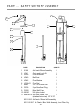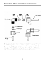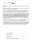
1
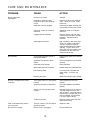
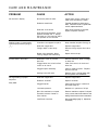
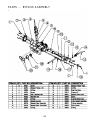
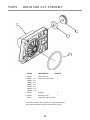
INSTALLATION
AND SERVICE
MANUAL
VERSION 1.0
WM. R. Hague, Inc.
4343 S. Hamilton Road,
Groveport, OH
43125
Table of Contents
PREFACE ................................................................................................................
1
PRE-INSTALLATION ................................................................................................
2
INSTALLATION AND START UP ............................................................................
3
EQUIPMENT SPECIFICATIONS ...........................................................................
4
SETING CHARTS ..................................................................................................
6
CYCLES .................................................................................................................
8
SETTING THE HYDROCLEAN SYSTEMS CONTROLLERS ................................
10
CARE AND MAINTENANCE .................................................................................
15
PARTS ...VALVE ASSEMBLY .................................................................................. 17
PARTS ... HOOK-UP / COVER ASSEMBLY ...........................................................
18
PARTS ... RESIN TANK ASSEMBLY .......................................................................
19
PARTS ... BRINE TANK ASSEMBLY .......................................................................
20
PARTS ... OPTIONAL BRINE TANK ASSEMBLY ...................................................
21
PARTS ... INJECTOR ASSEMBLY .......................................................................... 22
PARTS ... BRINE VALVE HOUSING ASSEMBLY ....................................................
23
PARTS ... BYPASS ASSEMBLY ..............................................................................
24
PARTS ... I/O ADAPTER ASSEMBLY ..................................................................... 26
PARTS ... DRIVE END CAP ASSEMBLY ................................................................ 28
PARTS ... DRAIN END CAP ASSEMBLY ................................................................
30
PARTS ... SAFETY SHUTOFF ASSEMBLY ............................................................. 31
BRINE VALVE ELBOW INSTALLATION INSTRUCTIONS ..................................... 32
WARRANTY ............................................................................................................
33
PREFACE
Congratulations on your decision to place
your confidence in a superior Hague
Hydro-Clean® water treatment appliance.
information is contained in this manual
which will help you attain the maximum
benefit and enjoyment from your particular
model.
Recognized nationwide for built-in quality,
dependability, and ease of service, these
appliances represent state-of-the-art in
home water treatment.
We urge you to read this information carefully and review it again at any time a malfunction may occur. In most cases, this
review will uncover minor problems that
you can correct yourself, thereby saving
you time and the expense of an unnecessary service call.
While your appliance should be
installed and serviced by a professional
Hague Hydro-Clean dealer, important
HOW TO GET THE MAXIMUM EFFICIENCY FROM YOUR HYDRO-CLEAN APPLIANCE
1. Maintain salt level (for iron filter, see
Page 6) at least one-third full; solar salt or
pellets and purchase a clean grade of salt.
Use one or the other; do not mix pellets
and solar salt.
the appliance back into service.
Your Hydro-Clean III appliance may be
disinfected with 5.25% sodium hypochlorite, which is the active ingredient in household bleach. To disinfect your appliance,
add 4 fluid ounces of hypochlorite solution
per cubic foot of resin to the brine well of
the brine tank. (the brine tank should have
water in it to permit the solution to be carried into the softener). Initiate a manual
regeneration.
2. Should your electricity be turned off for
any reason, more than 16 hours. Reset the
time of day according to instructions on
page 14.
3. Allow the appliance to regenerate at a
time when the water is not being used. If
you have more than one appliance, allow
two hours between each regeneration.
EXAMPLE:
HCIII 25 = 3.2 oz. Chlorine
HCIII 25CX = 4.0 oz. Chlorine
HCIII 35 = 4.4 oz. Chlorine
HCIII 48 = 6.0 oz. Chlorine
HCIII 64 = 8.0 oz. Chlorine
HCIII 105 = 13.2 oz. Chlorine
4. Protect your Hydro-Clean III system,
including the drain line, from freezing.
5. Should dirt, sand or large particles be
present in your water supply, it is important
that you consult your Hague dealer to
determine the appropriate treatment
method that will eliminate this problem.
OPERATIONAL, MAINTENANCE AND
REPLACEMENT REQUIREMENTS ARE
ESSENTIAL FOR THE PRODUCT TO
PERFORM TO SPECIFICATIONS.
6. Bypass the appliance if well, plumbing,
or pump work is required, and turn on outside tap until water runs clear before putting
1
PRE-INSTALLATION CHECK LIST
4. Electricity - Use standard 110 volt A.C.
(optional 220 volt available).
1. Water Pressure - Not less than 20 PSI
constant for models HCIII-(25, 35, 48, 2TN)
30 psi for HCIII-64, 105 and filters.
5. Water Quality - If water supply contains
sulfur, bacteria, iron bacteria, tannins,
algae, oil, acid, salt or other unusual substances, special equipment must be
installed ahead of the Hydro-Clean III
system. See pages 5 and 6.
2. Service Flow Rate - 5 G.P.M. recommended as minimum, 7 GPM for filters.
3. Drain - Drain the appliance to the floor
drain or washer drain. To prevent backsiphoning, the installer must provide an
adequate air gap or a siphon break.
SOME DO'S
SOME DON'TS
1. Do install after the pressure tank and
not between the well pump and pressure
tank.
1. Do not install if previous items are not
satisfactory.
2. Do not install if incoming or outlet piping
water temperature exceeds 120 ºF.
2. Do comply with all local plumbing and
electrical codes.
3. Do not allow soldering torch heat to be
transferred to valve components or plastic
parts.
3. Do install pressure reducing valve if
inlet pressure exceeds 90 PSI.
4. Do examine the inlet line from the pressure tank to appliance on well water with
iron (recommended minimum inlet pipe
size 3/4" I.D.). On municipal water, recommended minimum inlet pipe size is 1/2" I.D.
5. Do install gravity drain on salt storage tank.
6. Do secure drain line on appliance and
at drain outlet.
7. A minimum of 10 feet of 3/4" pipe from
the outlet of the water conditioner to the inlet
of the hot water heater is recommended.
8. Do install the drain line so that there is a
2" air gap between the drain line and the
drain receptacle.
2
INSTALLATION and START UP
Place the appliance in the desired location.
Turn off the electricity and/or water supply
to the water heater. Make sure the inlet,
outlet and drain connections meet the
applicable local codes. If the appliance
has a bypass valve, check the arrows on
the bypass valve to be sure the water flows
in proper direction. Caution: Do not plumb
the appliance in backwards.
Connect transformer power cord to the
back of the controller.
Plug in transformer.
Program the Systems Control as outlined
on pages 10 - 16.
Add water to the brine tank. Fill to a minimum of 2" above the grid plate. Make
sure that the salt dosage is set as recommended for the application. After the first
regeneration, the appliance will automatically refill the correct amount of water into
the brine tank.
The drain hose must be a minimum of 1/2"
I.D. tubing and should make the shortest
run to a suitable drain.
Connect the salt tank to the valve head
with the flexible 3/8" plastic tube included
with the system. Be sure to insert the
plastic insert in the end of the tube.
Put appliance into a manual regeneration
and inspect for proper operation. Allow the
appliance to draw all the water out of the
brine cabinet until the air check sets. Then
advance to the brine refill position by using
the Immediate Recharge or Change &
Select buttons simultaneously (depending
on controller). Allow the controller to complete the brine refill sequence of the program and advance to home position. This
will replace the necessary volume of water
relative to the salt setting.
Connect the Overflow Line to the brine
tank. If the brine tank is filled with too
much water, or if there is a malfunction, an
overflow line will direct excess water to drain.
The overflow line must end at a drain that
is at least 3" lower than the bottom of the
overflow fitting. Maintain a minimum of 2”
(50 mm) air gap.
Attach the drain line. Route the drain line
to a floor drain, laundry tub or other suitable waste receptor. Maintain a minimum
of 2" (50 mm) air gap between the drain
line and the flood level rim of the waste
receptor to prevent back siphoning.
Fill the brine tank with salt.* Note: Do not
mix pellet with solar salt!
* When using potassium chloride as an
alternative to sodium chloride, increase the
hardness setting by 12%. Note: We do
not recommend using potassium chloride
when iron is present in the raw water supply.
Place the appliance in the bypass position
and turn on the main water supply. Open
the nearest cold water faucet to flush the
plumbing of any excess soldering flux, air,
or any other foreign material.
Open the inlet valve and turn on the electricity to the water heater. To complete the
installation, open a cold water tap and
allow the appliance to flush for 20 minutes
or until approximately 72 gallons have
passed through the appliance. Verify flashing light on controller, indicating water flow.
Make sure the bypass valve is left in the
"service" position.
Close the faucet and check for leaks. If
leaks are found, turn off the main water
supply and open the nearest cold water
faucet to depressurize the water line.
Close the faucet to eliminate siphoning action.
Repair leaks. Place the bypass in the "service" position. Slowly open the main water
supply valve and fill the appliance. Then
open the nearest cold water faucet to purge
air out of the appliance. Close faucet.
Replace covers.
3
PRELIMINARY ENGINEERING SPECIFICATIONS
5
**
Quartz Gravel (lbs)
30-120
375*
375*
375*
385*
640
640
10
12
12
14
20
30
STANDARD FEATURES:
LEGEND:
Metered or timed HCIII
valve, Hydro-Clean
distributor, high capacity
resin and self-leveling
thermo media tank.
2 When iron is present in the
raw water supply, regeneration
frequency cannot exceed 96
hours. Additionally, a minimum
salt setting of 7 lbs. per cubic
foot of resin is required and the
#1 backwash must be
increased to 10 minutes.
OPTIONS:
Low profile valve cover, 1"
full flow bypass valve.
30-120
N/A: No Application
*325 lbs with grid plate.
4
** Do not use standard 18” diameter
brine tank with salt grid for salt
settings less than 3 lbs.
PRELIMINARY ENGINEERING SPECIFICAT I O N S
5
*Uses 4 oz. Potassium Permanganate (KmNO4.) See HC III - 2IF below
SPECIAL SERIES
LEGEND:
Standard: HCIII valve,
self leveling thermo media
tank, ¾" inlet/outlet adaptor, 1" high flow distributor.
Option: Built-in bypass
with test port, tank jacket,
salt shelf.
HCIII2TN: Designed to
remove tannin from iron
and sulfur free water.
Regenerates every 4th
day with 6 lbs. of salt. Add
4-oz. of 5¼% chlorine
every 6 weeks.
1 CAUTION: The HCIII1NF
will raise the pH of most, but
not all low pH water. Some
water requires the addition of
caustic soda with a chemical
feed pump.
Streamline brine tank 11" X 11" X 34" (not available for 2TN, 2IF, 64 or
105.)
HCIII2IF: Removes iron
and iron algae. Also
removes up to 5 ppm H2S
with the presence of 2ppm
iron. Regenerates every 6
days for iron; as needed
for sulfur.
2 When iron is present in the
raw water supply, regeneration frequency cannot exceed
96 hours. Additionally, a minimum salt setting of 7 lbs. per
cubic foot of resin is required
and the #1 backwash must
be increased to 10 minutes.
HCIII1CF: Removes
tastes, odors and will
reduce most man-made
pollutants. Backwashes as
needed.
HCIII1NF: Designed to
raise the pH of most low
pH water. The mineral
media must be
replenished periodically.
Backwashes every 2 days.
HCIII1MMF: Designed to
remove heavy sediment
and suspended solids. It is
capable of filtering down
to 10 microns in size.
Backwashed as needed.
5
3 Not available with 3-button
controller.
4 Water containing 10 grains
of hardness or more should
be softened prior to the tannin removal unit. To prevent
organic fouling, do not
exceed 4 days between
regenerations.
N/A: No Application
HCIII SPECIAL SERIES SETTING CHART
Capacity (ppm)
Sulphur H2S (ppm)
Iron (ppm)
HCIII21F
HCIII1CF
HCIII1MMF
HCIII INF
HCIII2TN
8,000
N/A
N/A
N/A
2 Tannin
5
N/A
N/A
N/A
0
20
N/A
N/A
N/A
0
7
N/A
N/A
5
7
Manganese
Greensand
Activated
Carbon
Multi-Grade
Calcite/Corosex
Anion Resin
Media Amount (cu. ft.)
1.0
1.33
1.5
1.25
.7
Quartz Gravel (lbs)
14
14
16*
14
10
Media Tank Size (in.)
10 X 47
10 X 47
10 X 47
10 X 47
8 X 44
Backwash Rate (gpm)
5.0
5.0
7.0
5.0
1.2
Brine Line Flow Control (gpm)
.5
N/A
N/A
N/A
.5
30 - 120
30 - 120
30 - 120
30 - 120
20 - 120
Mode Setting
1
1
1
1
1
Backwash #1 (min)
5
7
7
7
5
45
0
0
0
30
2
0
0
0
2
3
0
0
0
7
4 oz. KMn04
Potassium
Permanganate
N/A
N/A
N/A
Salt
Backwash only unit.
Must backwash at
least every two days
or media may solidify.
Will add some
hardness to water.
Regenerates every
4 days.
Minimum pH
Media Type
Water Pressure
Brine/Rinse (min)
Backwash #2 (min)
Salt (lbs) or Salt Substitute
Regenerant Used
This unit removes
H 2S with the pres ence of at least 2
ppm iron.
Backwash only
unit.
Must not be
backwashed for 24
hours after installation.
Backwash only
unit.
Backwashes every
3 days or as needed.
*The HCIII1MMF uses garnet for an under bed instead of quartz gravel.
6
HCIII SETTING CHART
MODE 1 & 2 SETTINGS
Dual mode five button controller
**
** Do not use standard 18” diameter brine tank with salt grid for salt
settings less than 3 lbs.
7
CYCLES
CYCLE 1
1. First up-flow backwash.
A rapid up-flow of water flushes out the resin bed and
cleans the sediment filter.
Resin Level
Salt Level
Brine Level
CYCLE 2
2. Brine. Brine is drawn out of
the brine cabinet and up
through the media tank, cleaning the resin bed and releasing
accumulated hardness and iron.
Resin Level
Brine Level
CYCLE 3
Resin Level
3. Slow rinse. A slow up-flow
rinse process then flushes out
the brine, hardness and iron.
Brine Level
8
CYCLES
CYCLE 4
Resin Level
4. Second up-flow backwash.
This up-flow backwash flushes
out any remaining brine
solution and sediment from
cycle 2.
Brine Level
CYCLE 5
5. Downflow soft water brine refill.
Soft water is directed to the brine
cabinet to prepare the brine for the
next regeneration sequence.
Resin Level
Brine Level
CYCLE 6
Resin Level
Brine Level
6. Return to service. Regeneration
is complete and the appliance is
returned to normal operation.
9
SETTING & USING THE APPLIANCE CONTROL
SERVICE SETTINGS
This section is recommended for qualified service personnel only. The
appliance control must be set correctly for proper performance.
REGENERATE
FUNCTION: Multi-purpose. 1.) Used to put the appliance into an immediate regeneration. Press and hold (approximately 5 seconds) until display changes to "Going to 1". The appliance is now in regeneration and
will return to "Gal. Remain" after completion of all cycles. 2.) Used to
“speed up” or toggle through all the regeneration cycles.
CUSTOMER SETTINGS
This section is recommended for qualified service personnel only. Must
be set correctly for proper performance.
CHANGE
FUNCTION: Used to change values of parameters that can be set.
Used in conjunction with SELECT button. Press and release the Select
Digit button to move cursor one digit to the right of parameter that can
be set. When cursor is at extreme right position, press again to reset
cursor to extreme left position.
figure 2
SELECT
FUNCTION: Used to control cursor movement when in CUSTOMER & SERVICE SETTINGS modes. Used in conjunction
with CHANGE button. Press and release the Select Digit button to move cursor one digit to the right of parameter that can be
set. When cursor is at extreme right position, press again to reset cursor to extreme left position.
DISPLAY
FUNCTION: When pressed and held, “CUSTOMER SETTINGS” is displayed. Hold for 5 seconds and the customer programming mode is entered. Used simultaneously with the SELECT button to enter service settings program mode, press and hold
both buttons for 5 seconds while holding “SERVICE SETTINGS” is displayed. (Note: both buttons must be pressed.)
SCROLL BACK
FUNCTION: Used to toggle back to the previous parameter setting in the event of a mistake in programming. This feature
eliminates the need to toggle through the entire program to correct an input error.
CONTROL PANEL DISPLAY:
LCD DISPLAY
FUNCTION: Shows status of control; NORMAL OPERATING mode, SERVICE SETTINGS mode or CUSTOMER SETTING
mode. It is very important to know which mode the control is in for proper operation.
WATER FLOWING INDICATOR
FUNCTION: Shown in the LCD display, it indicates that water is flowing through the HCIII. Flow rate is displayed in gallons
per minute. This is useful for checking for proper plumbing and leaks.
10
SETTING & USING THE APPLIANCE CONTROL
Description Of The Two HCIII Operating Modes
CAUTION: Be sure the controller is firmly "locked" onto the drive end cap assembly." The four tabs on top of the drive end
cap will allow the clips on the bottom of the controller case to lock onto the end cap tabs. (See detail diagram on page 19;
fig. 3.)
MODE 1
TIMER MODE: Will regenerate based on frequency. Example: every 2 days or as specified up to 12 days.
Time of regeneration can be set.
MODE 2
PATENTED SAVEMATIC - DEMAND DELAYED: Is based on actual water usage and total capacity of the appliance.
Time of regeneration can be set. If total capacity is depleted before set regeneration time, a forced regeneration will
occur.
Note: Mode 1 and 2 are equipped with capacity Gard. This ensures that you do not run out of conditioned water due to
excess water usage.
THE FOLLOWING EXAMPLE takes you through the steps involved for setting the HCIII SYSTEM CONTROL. If you
follow these steps, you will set HCIII 35 for OPERATING MODE 2, DEMAND DELAYED operation. Mode 1 uses a similar procedure. It is necessary to enter the “SERVICE SETTINGS” first, followed by the “CUSTOMER SETTINGS”. Press
and hold the SELECT and DISPLAY buttons simultaneously for 5 seconds. The display will show, “Soft Vers. 01.0
Release both buttons.
1.00
Push the CHANGE DIGIT button until the correct language is displayed. In this example,
set to: Set Language ENG.
2.00
Push the DISPLAY button to step to the next parameter. The display will show: Units ENG
2.00a
Push the CHANGE button to toggle English/metric units of measure.
For this example, set to: Units ENG.
3.00
Push the DISPLAY button to step to the next parameter. The display will show: Mode 2 The “Mode #” is the
number of the OPERATING MODE for which the systems control is set. For this example, leave at: Mode 2.
4.00
Push the DISPLAY button to step to the next parameter. The display will show: Hard. Gr. 040 The 040 is the
hardness number of the water tested. This number is to be the actual hardness reading and is not
compensated for iron.
4.00a
Push and release the SELECT button until the cursor ( _ ) is positioned in the display as follows:
Hard. Gr. 040. The cursor is now under the "ten" position.
4.00b
Continue pushing the SELECT and CHANGE buttons until the desired hardness number is displayed.
Example: Hard. Gr. 025
5.00
Push the DISPLAY button to step to the next parameter. The display will show: Iron ppm 00
This parameter is used to calculate a compensated hardness automatically.
5.00a
Push the SELECT and CHANGE buttons until the desired iron number is displayed.
Example: Iron ppm 00
6.00
Push the DISPLAY button to step to the next parameter. The display will show: Mang. ppm 00
6.00a
Push the SELECT and CHANGE buttons until the desired manganese number is displayed.
Example: Mang. ppm 00
6.00b
Push the DISPLAY button to step to the next parameter. The display will show: SALT = Sodium.
WARNING! When iron and/or manganese is present in the water supply, do not use potassium chloride as a
regenerant. Iron and/or manganese bacteria may develop and foul the conditioning media and may void the
warranty.
6.00c
Push the SELECT and CHANGE buttons until the desired regenerant is selected. EXAMPLE: Salt = Sodium.
11
SETTING & USING THE APPLIANCE CONTROL
7.00
Push the DISPLAY button to step to the next parameter. The display will show: Comp. Hard. 00025
This parameter is the calculated compensated hardness using the hardness, iron and manganese settings.
The formula is (4 x each ppm iron) + (4 x each ppm manganese) + hardness = compensated hardness.
This is not a parameter that can be set. The display should now read: Comp. Hard. 00025
8.00
Push the DISPLAY button to step to the next parameter. The display will show: Capty. Gr. 28730
This parameter is used to set the softening capacity of the appliance. (See WaterMax engineering
specifications or setting charts for capacities based on salt usage.)
8.00a
Push the SELECT and CHANGE buttons until the desired capacity number is displayed.
In this example, set to: Capac. Gr. 24500
9.00
Push the DISPLAY button to step to the next parameter. The display will show: 72-96hr Regen Yes
This parameter, if set to "Yes", is used to force the appliance to regenerate every 96 hours if regularly
scheduled regenerations based on water usage do not occur in 96 hours or less intervals. This should
always be "yes" if iron is present in the water.
9.00a
Push CHANGE button to toggle parameter value from "No" to "Yes". In this example, set to: 96hr Regen No
10.00
Push the DISPLAY button to step to the next parameter. The display will show: Backwash 1 01.0
(See Mode 1 & 2 setting chart.) The “01.0” is the time, in minutes to the nearest tenth, for which the first
backwash cycle can be set.
10.00a Push the SELECT and CHANGE buttons until the desired backwash time is displayed.
In this example, set to: Backwash 1 06.0
11.00
Push the DISPLAY button to step to the next parameter. The display will show: Brine/Rinse 30.0
The "30.0" is the time, in minutes to the nearest tenth, for which the first brine and slow rinse cycles
can be set.
11.00a
Push the SELECT and CHANGE buttons until the desired combined brine and slow rinse cycle time is
displayed. In this example, set to: Brine/Rinse 25.0
12.00
Push the DISPLAY button to step to the next parameter. The display will show: Backwash 2 05.0
The "05.0" is the time, in minutes to the nearest tenth, for which the second backwash can be set.
12.00a Push the SELECT and CHANGE buttons until the desired backwash time is displayed.
In this example, set to: Backwash 2 02.0
12
SETTING & USING THE APPLIANCE CONTROL
13.00
Push the DISPLAY button to step to the next parameter. The display will show: Salt lbs. 06.2
This parameter sets the amount of salt to be used to achieve the capacity setting.
13.00a Push the SELECT and CHANGE buttons until the desired salt setting is displayed.
In this example, set to: Salt lbs 05.5
14.00
Push the DISPLAY button to step to the next parameter. The display will show: Turbine Test NO
This feature should only be used by qualified service personnel. It is intended to be used for diagnostic
purposes only. WARNING! Do not engage this feature.
14.00a Push the SELECT and CHANGE buttons until the correct value is displayed.
In this example, set to: Turbine Test NO
15.00
Push the DISPLAY button to step to the next parameter. The display will show: Reg. Tonight NO
This parameter, if set to YES, will force a regeneration at the next set regeneration time (i.e. 02.00.) After
the regeneration, the parameter will automatically reset to "No."
15.00a Push the CHANGE button to toggle between Yes or No. In this example, set to: Reg. Tonight YES
16.00
Push the DISPLAY button to step to the next parameter. The display will show: Filter? No.
This parameter, if set to YES, is for model selection only and has no effect on the function of
the appliance. In this example, set to: Filter, NO.
17.00
Push the DISPLAY button to step to the next parameter. The display will show:
Gal. Remain 00980
13
SETTING & USING THE APPLIANCE CONTROL
This is the normal operation display for OPERATING MODE 2. The 00980 represents the number of
gallons of softening capacity between regenerations. This completes the SERVICE SETTINGS mode.
Even though the SERVICE SETTING mode has been completed, the HCIII 35 is not ready for service
until the CUSTOMER SETTINGS mode is completed. The following example takes you through the steps
required for setting the parameters of the CUSTOMER SETTINGS mode for OPERATING MODE 2.
1.00
Push and hold the DISPLAY to enter CUSTOMER SETTINGS mode. The display will show:
Set Time 00:00 AM This parameter is to be set to the current time of day.
1.00a
Push the SELECT and CHANGE buttons until the desired time is displayed.
In this example, set time to: Example: 11:00 AM or 05:00 PM.
2.00
Push the DISPLAY button to step to the next parameter. The display will show: Reg Time 02:00 AM
This parameter is to be set for the desired time a normally scheduled regeneration is to occur.
2.00a
Push the SELECT and CHANGE buttons until the desired time is displayed.
In this example, set to: Reg. Time 02:00. (02:00 is 2:00am)
3.00
Push the DISPLAY button to step to the next parameter. The display will show: # People 04
3.00a
Push the CHANGE button until the correct number of people in the household is displayed.
In this example, set to: # People 05
5.00
Push the DISPLAY button to save the parameter settings and exit the CUSTOMER SETTINGS mode.
The display will show: Gal Remain 00980
If you followed the above directions correctly, your HCIII Systems Control
is ready for OPERATING MODE 2 service.
14
CARE AND MAINTENANCE
PROBLEM
CAUSE
ACTION
No soft water after
regeneration.
No salt in brine tank.
Add salt.
Sediment in brine tank has
plugged the brine line and/or air
check.
Remove the brine line and flush
clean. Clean air check. Clean
brine tank.
Refill flow control is plugged.
Remove brine piston housing and
clear debris from the flow control.
Drain line is pinched, frozen or
restricted.
Straighten, thaw or unclog the
drain line.
Clogged injector assembly.
Remove injector cap and clean
nozzle and throat with a wooden
toothpick. Replace throat if
removed.
Salt bridge has formed.
High humidity or the wrong kind
of salt can create a salt bridge.
This is a crust that forms an
empty space between the water
and salt. To test, use a blunt
object like a broom handle. Push
the handle into the salt to dislodge the salt bridge.
The plumbing bypass valve is in
the bypass position.
Place bypass valve in the service
position.
Appliance is plumbed in backwards.
Check that appliance is plumbed
correctly.
Extended power outage.
Reset hardness.
Water hardness has increased.
Retest water and reset hardness.
Not metering water.
Flow should be indicated with
water usage. If no flow, see
below.
Blending dial open.
Make sure blending dial is closed.
The bypass valve is in the bypass
position.
Place bypass in the service
position.
Appliance plumbed in backwards.
Check that appliance is plumbed
properly.
Sensor not receiving signal from
magnet.
Remove sensor from I/O housing.
Test with magnet on each flat
side of sensor. One side should
indicate flow, the other will not. If
flow is indicated, check trubine.
If no flow, replace sensor.
Turbine is jammed.
Remove bypass valve and clear
debris from turbine.
Flow is indicated when water is
not being used.
There is a leak in your household
plumbing system.
Repair the leak.
No read-out in display.
Electric cord is unplugged.
Plug in transformer.
No soft water
No flow is indicated when water
is flowing.
15
CARE AND MAINTENANCE
PROBLEM
CAUSE
ACTION
No read-out in display.
No electric power at outlet.
Check power source. Make sure
outlet is not controlled by a switch.
Defective transformer.
Test with volt meter for 12VAC at controller. If less than 10VAC or greater than
14VAC, replace transformer.
Defective circuit board.
With 12VAC present at controller,
replace computer controller.
High ambient temperature. If temperature exceeds 120° F, display
will blank out. This does not affect
the operation of the controller.
Appliance stays in regeneration.
Cycle display remains "going to
_?_".
Controller not snapped into place.
Snap controller into place. See pg. 18
Defective magnet disc.
Replace magnet disc.
Foreign object in valve body.
Remove foreign objects from valve
body.
Broken valve assembly. Motor
running. Magnet disc not turning.
Repair drive end cap.
Restricted, frozen or pinched
drain line.
Remove restriction, thaw or straighten drain line.
Plugged brine line, brine line flow
control or air check.
Clean flow control, air check and
brine line.
Plugged injector assembly.
Clean or replace injector. Replace
throat if removed.
Sticking brine refill valve.
Remove valve. Lubricate piston with
silicone grease and reassemble.
Not regenerating in proper
sequence.
Defective magnet disc.
Replace magnet disc.
Defective controller.
Replace controller.
Salty water.
Plugged Injector.
Clean injector screen, nozzle and
throat See page 22.
Low water pressure.
Maintain min. pressure of 30 psi.
Brine line restricted or crimped.
Remove restrictions, replace if crimped.
Excessive amount of water in
brine cabinet.
Verify correct water level relative to salt
setting. Check lines for loose connections.
Insufficient rinse time.
See mode settings (page 7). Adjust time
if necessary.
Excess water in brine tank.
16
PARTS ... VALVE ASSEMBLY
12
4
5
8
1
9
6
7
3
2
7
12
13
10
14
15
11
1
2
3
4
5
6
7
8
9
PART#
53000
93501
90614
90615-94
95301T-JG
90828
93808
93229
93838
DESCRIPTION
QUANITY
Valve Housing
1
Injector Assembly
1
Drain Endcap Assembly
1
Bypass Assembly
1
Drive Endcap Assembly *
1
Small End Cap O-ring
1
End Cap O-ring
2
Flow Director
1
I/O Adapter O-ring
2
10
11
12
13
14
15
* This assembly does not include a magnet disc or
drive motor, and must be ordered seperately.
17
PART#
93835
93809
93870
H2281
H3304
53004
DESCRIPTION
Spacer Tube
End Cap Screw
End Cap Screw
Tank O-ring
Pilot O-ring
Pilot O-ring Retainer
QUANITY
2
2
4
1
1
1
PARTS ... HOOK-UP / COVER ASSEMBLY
9
7
4
8
1
5
6
3
10
2
PART#
53500
BT844
BT948
BT1047
BT1054
3 93245
4 53501
5 54550
6 H2281
7 90837
8 90254
9 90251
90256
10 95209
Controller Tab Lock Detail
1
2
Correct
Incorrect
18
DESCRIPTION
QUANITY
Valve Cover W/Label
1
Resin Tank Jacket
1
Resin Tank Jacket
Resin Tank Jacket
Resin Tank Jacket
Transformer
1
Valve Assembly w/O-ring
1
5 Button Controller
1
Tank O-ring
1
Hook Up O-ring
2
Copper Adapter
2
Bypass Nut
2
PVC Adapter (optional)
2
Clear Viewing Panel
1
PARTS ... RESIN TANK ASSEMBLY
1
PART#
DESCRIPTION
BT 844
Thermo Jacket - 44
BT 1047
Thermo Jacket - 47
BT 948
Thermo Jacket - 48
BT 1054
Thermo Jacket - 54
2
C1400
C1430
C1480
Thermo Foam - 8"
Thermo Foam - 9"
Thermo Foam - 10"
2
3
MT844
MT948
MT1047
MT1054
MT1252
MT1465
Thermo Tank - 8"X44"
Thermo Tank - 9"X48"
Thermo Tank - 10"X47"
Thermo Tank - 10"X54"
Thermo Tank - 12"X52"
Thermo Tank - 14"X65"
3
CAS-820
CAS-822
CAS-823
CAS-824
CAS-827
CAS-828
1"
1"
1"
1"
1"
1"
1
4
4
Riser HCIII Special Series
Riser HCIII 2TN, 25
Riser HCIII 25CX, 35
Riser HCIII 48
Riser HCIII 64
Riser HCIII 105
5
5
M010
M030
M048
M050
M060
M090
Resin - C249
Manganese Greensand
Activated Carbon
Calcite
Corosex
Calcite / Corosex Mix
6
M035
Quartz Gravel
7
MT181
MT182
MT183
Adjustble Base - 8"
Adjustble Base - 9"
Adjustble Base - 10"
2
6
7
19
PARTS ... STANDARD BRINE TANK ASSEMBLY
1
2
3
4
5
6
1
2
3
4
5
6
7
PART#
BT055
BT1833-HWC
C0700
93811-26.5
C0800
C0650
93848
53560
DESCRIPTION
QUANITY
Brine Tank Cover
1
Brine Tank
1
Overflow Fitting
1
Air Check Assembly
1
Brine Well
1
Grid Plate
1
3/8" X 5' Brineline (not shown)
Brine Tank Assembly (contains items 1-7)
20
PARTS ... OPTIONAL BRINE TANK ASSEMBLY
HCIII Square Brine Tank
15” X 15”
Compact Brine Tank
11” X 11”
Potassium Tank
1
1
2
3
4
7
3
5
2
8
5
6
4
PART# DESCRIPTION
QUANITY
PART#
DESCRIPTION
QUANITY
PART#
DESCRIPTION
QUANITY
Pot. Tank Cover
1
1 54006
Brine Tank Cover
1
1 BT092
Compact Brine Tank Lid
1
1 BT1425
2 90103
Brine Well Cap
1
2 BT1134
Compact Brine Tank
1
2 BT1424 Solution Tank
3 54525
Safety Shutoff Assembly
1
3 93811-26.5 Air Check Assembly
1
3 H5300-IF Air Check Assy., Iron Filter 1
4 54007
Support Panel (BT)
1
4 C0675-3.5 Compact Grid Plate
1
4 H5228
5 CO700A Cabinet Overflow
1
5 CO700
2 Piece Overflow
1
5 10700-IF Float Assy., Iron Filter
1
6 54008
Brine Well
1
6 93848
3/8” Brine Line (not shown)
6 H5785-IF Air Check, Iron Filter
1
7 54009
Grid Plate
1
53570
7 C0830
3’ X 6” Brine Well
1
8 54003
Cabinet
1
Compact Brine Tank Assembly
(contains items 1-6)
8 CO700
2 Piece Overflow
1
9 93848
3/8” Brine Line (not shown)
UAS-120
21
Safety Brine Valve
Potassium Tank Assembly
(contains items 1-9)
1
1
PARTS ... INJECTOR ASSEMBLY
1
2
3
4
5
7
6
1
2
3
4
5
6
7
PART#
93223
93223-64*
93223-105**
93220
93221
93221-64*
93221-105**
93232
93222
90807
93810
DESCRIPTION
QUANITY
Injector Throat
1
Injector Throat
Injector Throat
Bottom Injector Seal - thick
1
Injector Nozzle
1
Injector Nozzle
Injector Nozzle
Top Injector Seal - thin
1
Injector Cap
1
Injector Screw
4
Injector Screen
1
93501
Injector Assembly (contains items 1-7)
* For use on 12" diameter softener tank only.
** For use on 14" diameter softener tank only.
22
PARTS ... BRINE VALVE HOUSING ASSEMBLY
23
PARTS ... BYPASS ASSEMBLY
24
PARTS ... BYPASS ASSEMBLY
90246 Bypass Housing: Makes the connection
between the plumbing and Main Valve Body. Also,
contains the "Hard Water" Blending Valve and
Bypass Piston. The recommended seal for the
1-1/4" male inlet-outlet threads is the plastic
Hook-up Nut (90251), O-ring (90837), and Copper
Adapter (90254). Make sure the O-ring is between
the Housing and Copper Adapter. The O-ring seal
areas at the Main Valve Body inlet and outlet must
to be smooth and free of defects and debris, and
lubricated with silicone grease before assembling.
When attaching to the Main Valve Body, put the
O-rings on the male bosses on the Valve Body and
push the Bypass into place. A "snap" can be heard
when the Bypass slides into place. When released,
the Bypass should stay in place; if not, the O-rings
may be "pinched." If the O-rings are pinched,
replace with new ones. The Bypass comes
pre-assembled with the Sensor housing and turbine
axle. These are not field serviceable and if damaged, must be replaced with a new assembly. The
Bypass Piston bore is to be smooth and, at the
recessed areas, have a smooth transition (no sharp
corners) to the seat areas.
pressure (torque) will not improve the seal. Once
the Piston reaches the stop at either position, it can
be backed off up to one half turn of the handle and
still achieve a seal.
90616 Bypass Piston Assembly: The white teflon
Hydro-slide O-ring covers should be free of defects
such as indentations and cuts. The Piston should
move freely into and out of the Bypass Housing
without damaging the Hydro-slides. If the Hydroslides catch, tear or crimp, the Housing should be
replaced. Note: Some compression will occur when
the Hydro-slides pass through the seal areas.
93858 Turbine Sensor Assembly: Picks up the
magnetic field from the Turbine and relays it to the
Controller. The three wire assembly connecting the
"black wafer" Hall Effect Sensor to the Controller
board must not be severely bent (folded over), cut,
or broken. Care should be taken when putting the
Sensor into the Sensor Housing. The "spring" flap
below the Sensor must be gently bent over (on top
of) the Sensor, and then the Sensor slide all the
way into the Sensor Housing. The round hole of the
Sensor mounting tab is then placed down over the
mounting screw boss. The cap is then put in place
and the mounting screw is installed. A slot is provided in the cap for the wire way to exit. The threewire socket connector must be properly installed in
the controller. Stops on the connector prevent
improper (upside down) assembly. Do not force the
connector past the stops.
90262 Bypass End Cap: Left: Seals the left Piston
opening on the Housing (90246). The opening is
sealed with an O-ring used as an axial or "face"
seal. The O-ring sits in a groove in the End Cap.
This groove must be free of defects such as pits or
scratches and also free of debris. When assembling
the End Cap to the Housing, care should be taken
to make sure that the O-ring stays in the groove in
the End Cap. If misaligned, the O-ring can become
pinched and leak. Also, on the End Cap is the
Piston Axle, a 1/4" square shaft that acts as a
guide/slide and anti-turning mechanism for the
Bypass Piston.
90522 Turbine Assembly: The Turbine must have
a 1/8" diameter Rare Earth magnet pressed into
place adjacent to the axle opening. When assembled to the axle, the Turbine should spin freely. Do
not use any lubricants. If the Turbine should
become "jammed, clean and flush the Turbine and
Bypass Valve.
90263 Bypass End Cap- Right: Seals the right
Piston opening on the Housing (90246). The opening is sealed with an O-ring used as an axial or
"face seal. The O-ring sits in a groove in the End
Cap. This groove must be free of defects such as
pits or scratches and also free of debris. When
assembling the End Cap to the Housing, care
should be taken to make sure that the O-ring stays
in the groove in the End Cap. If misaligned, the Oring can become pinched and leak. Also, on the
End Cap is the guide/bushing for the Bypass Piston
Drive Shaft. There is an O-ring seal at the opening
for the Drive Shaft. This seal area must be free of
defects such as pits or scratches and also free of
debris.
90252 Blending Dial Cap: The Cap should be held
in place by the three 1/2" screws and be in the
proper orientation.
90222 Blending Valve: The valve permits the addition of "hard water" into the soft water outlet. It is
closed when pointing toward the Main Valve Body
and open when pointing toward the inlet side.
90226 Test Port Valve: The Test Port Valve is
used to draw water samples for testing of treated
water. Note: The Bypass must be in the "service"
position to get an accurate sample. There are two
types of seals on the Test Port. One seal is an Oring which seals off the threaded area when the
Valve is opened. The other seal is a compression
seal between the Test Port Valve material and the
Right End Cap material. If this seal is "overtightened', it can damage the sealing area on the End
Cap causing a permanent leak.
90218 Bypass Piston Drive Shaft: The Drive Shaft
has an acme thread which is used to move the
Piston from "bypass" to "service" position. When
operating the Bypass, to achieve either "service" or
'bypass', it is only necessary to turn the Handle
(90221) until the Piston (90616) stops. Additional
25
PARTS ...3/4" I/O ADAPTER ASSEMBLY WITH BLENDING VALVE
8
5
Note: Parts 12, 13 and 15 are not field
serviceable. Do not remove screws (#14)
6
1
7
12
13
14
9
15
3
4
2
10
PART#
1 93227
2 93858
3 90232
4 90522
5 90252
6 90222
7 90827
8 90802
9 93838
10 93229
11
DESCRIPTION
QUANITY
3/4" IO Adapter Assembly
1
Turbine Sensor Assembly
1
Turbine Sensor Cap
1
Turbine Assembly
1
Blending Dial Cap
1
Blending Dial
1
“O” Ring
1
#6 X .5 Screw
3
“O” Ring
2
Flow Director
1
11
12
13
14
15
26
PART#
90809
90828
93271
90802
90245
93521
DESCRIPTION
QUANITY
Sensor Cap Screw
1
Turbine Sensor Housing O-ring
2
Turbine Sensor Housing
1
Turbine Sensor Housing Screw
2
Turbine Axle
1
3/4" IO Adapter Assembly
(contains items 1-15)
PARTS ...1" I/O ADAPTER ASSEMBLY WITH BLENDING VALVE
8
5
Note: Parts 12, 13 and 15 are not field
serviceable. Do not remove screws (#14)
6
1
7
12
13
14
9
15
3
4
2
10
PART#
1 93252
2 93858
3 90232
4 90522
5 90252
6 90222
7 90827
8 90802
9 93838
10 93229
11
DESCRIPTION
QUANITY
1" IO Adapter Assembly
1
Turbine Sensor Assembly
1
Turbine Sensor Cap
1
Turbine Assembly
1
Blending Dial Cap
1
Blending Dial
1
“O” Ring
1
#6 X .5 Screw
3
“O” Ring
2
Flow Director
1
11
12
13
14
15
27
PART#
90809
90828
93271
90802
90245
93521-1
DESCRIPTION
QUANITY
Sensor Cap Screw
1
Turbine Sensor Housing O-ring
2
Turbine Sensor Housing
1
Turbine Sensor Housing Screw
2
Turbine Axle
1
1" IO Adapter Assembly
(contains items 1-15)
PARTS ... DRIVE END CAP ASSEMBLY
90821
54502
28
PARTS ... DRIVE END CAP ASSEMBLY
95301T-JG Drive End Cap: Seals the two
openings on the Main Valve Body. The larger
diameter opening is sealed with an O-ring
used as an axial or "face" seal. The O-ring sits
in a groove in the End Cap. This groove must
be free of defects such as pits or scratches
and also free of debris. The smaller diameter
seal is accomplished with an O-ring used as a
radial seal. The O-ring should be placed on the
male boss on the End Cap. When assembling
the End Cap to the Valve Body, care should be
taken to make sure the small O-ring is aligned
with the opening in the Valve Body and that the
large O-ring stays in the groove in the End
Cap. If misaligned, the O-rings can become
pinched and leak.
93238 Drive Gear: The Drive Gear is assembled to the Slide Cam by means of a "keyed"
opening which transfers the "torque" generated
by the Motor to the rest of the drive system. If
the drive system becomes jammed, this opening can become "rounded" causing the gear to
turn, but not the Piston Slide Cam. If this
occurs, clear the jam and replace the Drive
Gear and Piston Slide Cam (93217).
93514-AJG Brine Valve Assembly: Attaches
to the Drive End Cap with two 3/4" thread cutting screws and has one O-ring seal. The Oring is used as a axial or face seal. The O-ring
sits in a groove in the brine valve housing.
The groove and the face seal must be free of
defects such as pits and scratches or debris.
90217 Drive Motor: The Motor is held in place
by two 1/2" screws. The screws should be
"snug." The brass pinion gear on the Motor
should engage the plastic Drive Gear. The
wires should be securely fastened to the
Control.
93216 Piston Slide: The Slide should move
freely inside the End Cap Housing. The stainless steel threaded stud should be pointing
toward the Valve Body.
93217 Piston Slide Cam: This is the "heart" of
the drive system. There is a threaded stainless
steel shaft that runs through the main drive
axle. The Drive Gear is attached at
the short end and the Magnet Disc at the other
end. The Slide Cam is assembled inside of the
Piston Slide (93216). This Cam Shaft should
turn freely before the Motor is assembled.
93219 Piston Slide Cam Cover: The cover
secures the Piston Slide Cam (93217) in place
and acts as a bushing for the Cam Shaft.
29
PARTS ... DRAIN END CAP ASSEMBLY
1
3
2
4
PART#
DESCRIPTION
QUANITY
Drain End Cap
1
Drain Line Flow Control
1
3 90267
Retainer
1
4 93808
End Cap O-ring
1
1 90268
2 H2086
H2086
H2086
H2086
H2086
H2086
H2086
90614
- 1.2*
- 2.0*
- 2.4*
- 3.0*
- 4.0*
- 5.0*
- 7.0*
Drain End Cap Assembly
*The number shown after the drain Line Flow Control Button
part number indicates the back wash flow rate in gpm.
30
PARTS ... SAFETY SHUTOFF ASSEMBLY
9
10
1
2
8
7
3
4
5
3
11
6
PART#
1
2
3
4
5
6
7
8
9
10
11
DESCRIPTION
51366
H7041
H7039
H7040
H7042
H7038-01
90102
C0700
CO600
201120
93882-25.75
QUANITY
Air Check Elbow Assembly
1
Guide and Lock Set
1
Float Grommet
2
Bell Float
1
Float Washer
1
Float Rod
1
3.5 X 26.5 Brine Well
1
2 pc. Overflow Fitting
1
Brine Well Cap
1
3/8" Nylon Insert
1
Air Check Draw Tube
1
(standard brine tank) 18” X 33”
93811-26.5 Air Check / Brine Well Assembly
93811-20.0 IF Air Check / Brine Well Assembly, Iron Filter Only
31
Brine Valve Elbow Installation Instructions
The nut, gripper and retainer sleeve are a 3 piece assembly that can come apart if removed
from the elbow body. Parts must be re-assembled exactly as shown to function properly.
When connecting the 3/8” polytube, it is first necessary to assemble the nut, gripper and
retainer sleeve on the tubing before inserting the plastic insert, Screw the nut on the elbow
body. With a wrench, tighten nut securely to create a pressure tight connection.
32
Warranty
HAGUE Hydro-Clean® 10 Year Limited Residential Warranty
This warranty is issued to the original owner
only and is not transferable to subsequent owners.
In the event the water supply being processed
through this product contains bacterial iron, algae,
sulphur, tannins, organic matter or other unusual
substances, then unless the system is represented
as being capable of handling these substances in the
system specifications, other special treatment of the
water supply must be used to remove these substances before they enter this product. Otherwise,
Wm. R. Hague, Inc. shall have no obligation to supply replacement parts under this warranty.
TO PLACE THE EQUIPMENT UNDER WARRANTY,
THE WARRANTY REGISTRATION CARD MUST
BE COMPLETED AND RETURNED BY THE
OWNER TO WM. R. HAGUE, INC. WITHIN 30
DAYS OF INSTALLATION.
Coverage
This warranty covers the Hague Equipment delivered to the original owner, when the system is purchased for personal, family or household use. It is
intended to cover defects occurring in workmanship
or materials or both.
This warranty does not cover damage to a part(s) of
the system from causes such as fire, accidents,
freezing, or unreasonable use, abuse or neglect by
the original owner.
Warrantor's Performance and Length of Warranty
Wm. R. Hague, Inc. warrants that upon receipt from
the original owner of The Hague Equipment Mineral
Tank, Brine Tank, found to be defective in material or
workmanship, Hague will replace said part(s) at no
charge for those parts for 5 YEARS from date of
installation. And thereafter, will replace said parts
upon payment of the following percentages of the
then current list price: 6th through 10th year - 50% of
current price list.
This warranty does not cover damage to part(s) of
the system resulting from improper installation. All
plumbing and electrical connections should be made
in accordance with the installation instructions provided with the system. The warranty does not cover
damage resulting from use with inadequate or defective plumbing, inadequate or defective water supply or
pressure; inadequate or defective house wiring;
improper voltage, electrical service or electrical connections; or violation of applicable building, plumbing, or electrical codes, ordinances or regulations.
Wm. R. Hague, Inc. further warrants that upon
receipt from the original owner of The Hague
Equipment Valve and/or Power System Components
(i.e. complete valve controller) found to be defective
in material or workmanship, Hague will replace said
part(s), at no charge for those parts, for 3 YEARS
from date of installation.
This warranty is null and void unless the Hague
Hydro-Clean® System was purchased at retail from
an independent authorized Hague dealer and
installed by same.
Some states do not allow limitations on how long an
implied warranty lasts or the exclusion or limitation of incidental or consequential damages, so the
above limitations or exclusion may not apply to
you. This warranty gives you specific legal rights
and you may also have other rights which vary from
state to state.
Defective parts to be replaced must be returned,
along with the equipment serial number and date of
original installation, to Wm. R. Hague, Inc. PREPAID
and will be returned to the original owner FREIGHT
COLLECT.
THERE ARE NO WARRANTIES OTHER THAN
THOSE DESCRIBED IN THIS WARRANTY
INSTRUMENT. THIS WARRANTY DOES NOT
COVER INCIDENTAL, CONSEQUENTIAL OR SECONDARY DAMAGES.
For Owner's Reference
Equipment Serial No.
ANY IMPLIED WARRANTIES ON THE PRODUCT
DESCRIBED IN THIS WARRANTY WILL NOT BE
EFFECTIVE AFTER THE EXPIRATION OF THIS
WARRANTY.
Installation Date
This warranty does not cover any labor or service
call costs incurred with respect to the removal and
replacement of any defective part(s). Wm. R.
Hague, Inc. will not be liable for, nor will it pay any
labor or service call charges incurred or expended
with respect to this warranty.
Independent Dealer Name
Installer's Signature
33
© 2000
HYDRO-CLEAN III P.O. Box 298, Groveport, OH 43125
LITHO USA
Form #53120
RV0802HQWI