1
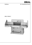
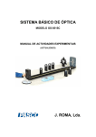
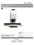
TECHNICAL MANUAL
TITAN 200
PAPER CUTTER
The Challenge Machinery Company
1433 Fulton Avenue
Grand Haven, MI 49417-1594 USA
Phone: 616-842-8300
Fax: 616-842-6511
ChallengeMachinery.com
TM. 200-A
MARCH 2000
INTRODUCTION The information contained in this document is intended solely for Challenge
trained service technicians. There may be situations that are not covered by this manual. The
information contained in this manual is to guide a technician to possible repair solutions. This
manual is to be used in conjunction with the TITAN 200 instruction and parts manual P/N F-200 (A).
TABLE OF CONTENTS
TABLE OF CONTENTS................................................................................................ 2
GENERAL INFORMATION......................................................................................................................... 5
ELECTRICAL SPECIFICATIONS ........................................................................................................... 5
MACHINE DIMENSIONS ........................................................................................................................ 5
MACHINE REVISIONS ................................................................................................................................ 6
TITAN MAIN BOARD REVISIONS ........................................................................................................ 6
CLAMP DAMPENER ASSEMBLY MOUNT REVISION....................................................................... 6
MANUAL MISPRINT ............................................................................................................................... 6
SINGLE CUT BUTTON REVISION......................................................................................................... 6
HYDRAULIC PUMP REVISION.............................................................................................................. 6
MANIFOLD SEAL REVISION................................................................................................................. 6
BACKGAUGE FUSE REVISION ............................................................................................................. 6
FRONT GUARD INTERLOCK SWITCH REVISION ............................................................................. 6
GENERAL HYDRAULIC INFORMATION................................................................................................. 7
HYDRAULIC FLUID CHANGE............................................................................................................... 7
PRESSURE GAGE..................................................................................................................................... 7
OPERATOR SETTING CLAMP PRESSURE .......................................................................................... 7
PRELIMINARY VALVE SETTING ......................................................................................................... 7
VALVE INFORMATION .......................................................................................................................... 7
SOFTWARE REVISIONS ............................................................................................................................. 8
ERROR CODES DESCRIPTIONS .............................................................................................................. 10
ERROR MESSAGES THAT DON’T REQUIRE A FLOW CHART...................................................... 10
ERROR MESSAGES THAT REQUIRE A FLOW CHART ................................................................... 11
SENSOR DATA ABBREVIATIONS AND MEANINGS....................................................................... 12
TITAN 200 TEST & ADJUSTMENT PROCEDURES ............................................................................... 13
TESTING DOWN VALVE COIL MAGNETISM................................................................................... 13
TESTING ANY HYDRAULIC VALVE SPOOL OPERATION ............................................................ 13
SEQUENCE OF ADJUSTING HYDRAULIC PRESSURES ................................................................. 13
TESTING AND ADJUSTING PROX SENSOR ..................................................................................... 13
MANUALLY ACTIVATING THE HYDRAULIC MOTOR.................................................................. 14
TESTING AND REPAIR OF BACKGAUGE BRAKE RESISTOR....................................................... 14
TESTING ENCODER .............................................................................................................................. 14
TESTING ENCODER/BACKGAGE ACCURACY................................................................................ 14
TESTING ENCODER CABLE ................................................................................................................ 15
TESTING INPUTS ON MAIN CIRCUIT BOARD................................................................................. 15
TESTING MAIN BOARD OUTPUT and OUTPUT DEVICES ............................................................. 15
INSTALLATION AND ADJUSTMENTS FOR OF THE KNIFE LATCH ASSEMBLY: ..................... 16
TEST BACKGUAGE ARMATURE........................................................................................................ 16
FRONT GUARD INTERLOCK SWITCH ADJUSTMENT ................................................................... 16
DISASSEMBLY OF SOLENOID COIL CABLE CONNECTOR .......................................................... 17
TESTING AND MANUALLY ACTIVATING KEYBOARD................................................................ 17
EE-2807 MAIN BOARD.............................................................................................................................. 18
BASIC MACHINE SCHEMATIC ............................................................................................................... 19
EE-2807-1..................................................................................................................................................... 20
Basic hydraulic schematic............................................................................................................................. 21
CHAMPION and TITAN CONSOLE PROGRAM MAP ............................................................................ 23
Hydraulic Motor didn’t start ......................................................................................................................... 24
Positioning error ........................................................................................................................................... 25
Clamp/Knife down........................................................................................................................................ 26
2
Clamp stuck down ........................................................................................................................................ 27
Slow backgauge movement to end of table................................................................................................... 28
Hydraulic up failure ...................................................................................................................................... 29
Knife down failure ........................................................................................................................................ 30
Sequence error .............................................................................................................................................. 31
Knife at both limits ....................................................................................................................................... 32
Clamp down failure ...................................................................................................................................... 33
Backgauge failure ......................................................................................................................................... 34
Shorted key error .......................................................................................................................................... 35
“Encoder wires 9 and 10 are reversed” or “Backgauge direction reversed” ................................................ 36
Knife latch failure 1 ...................................................................................................................................... 37
Knife latch failure 0 ...................................................................................................................................... 38
Hydraulic latch error 1 .................................................................................................................................. 39
3
SINGLE OPERATOR
Do not operate with more than one person.
SHOCK HAZARD
Disconnect power before removing cover.
Replace cover before operation
SHOCK HAZARD
Disconnect power before removing cover.
Replace cover before operation
HAZARD AREA
Disconnect power before cleaning, servicing or making
adjustments not requiring power. Do not alter safety guards
or devices, they are for your protection. Replace all guards,
do not operate with any guards removed.
4
GENERAL INFORMATION
ELECTRICAL SPECIFICATIONS
The cutter requires a 208/230vac 15-amp service. The cutter has a power cord, which requires a NEMA
6-15R or 6-20R receptacle. The proper way to test voltage is from before power up through a complete
cycle. The voltage must be tested at the
main fuse holders. The meter used must
have a reaction time of at least 100ms or a
low voltage record function. A low quality
meter will not respond fast enough to give
a true minimum voltage reading. Low
voltage to the cutter will blow the main
fuses. When the voltage drops, the 24vac
(solenoids) and 5vdc (computer) will have
problems. The low limit is 190 vac using
the above test. The high limit is 245 vac.
The voltage for the power panel can be
matched to the measured incoming
voltage. Reposition the jumper located in
the center of the terminal strip. Do not
remove any wires.
All Titan 200 s/n 981388 and down are 230vac only. If the voltage drop are 210vac or below during a
cut, a buck/boost transformer, p/n K-2834, is required. Note: The buck/boost can also be rewired to buck
voltage 250vac down. Call Challenge for rewiring. Always check the serial number tag to determine the
proper voltage range.
MACHINE DIMENSIONS
The Net weight is 755 LB (342kg). The height is 53”(135cm), length is 49” (124cm), and width is 36”
(91cm). Removal of the table, front guard and treadle will allow the machine to go through a 31 1/4”
(79.4cm) door way.
5
MACHINE REVISIONS
TITAN MAIN BOARD REVISIONS
The main circuit board, EE-2762, was changed to EE-2762-1. When using an EE-2762-1, the H-10 and
H-11 must not be connected.
Titan 200 cutters above s/n 971103 use EE-2807, the LCD display is no longer back lit. On EE-2807, the
H-10 jumper must be connected and H-11 jumper must not be connected. Both black plastic jumpers are
located near the F3 fuse. The EE-2807 can not be used for replacement a EE-2762 and EE-2762-1.
The EE-2807-1 is a direct replacement for the EE-2807. The H-10 jumper must be connected and the H11, 12, 13, 14 must not be connected.
CLAMP DAMPENER ASSEMBLY MOUNT REVISION
The upper mounting stud for the clamp-dampened cylinder has been changed to a three-piece mounting.
The first production Titan with the change is s/n 981319, (July-98). The part numbers are H-6938-416
(1/4x20x1"set screw), E-1152-68 (1/4x20x1"hex spacer), H-6918-412 (1/4x20x1½" cap screw). If the stud
is broken, it can be removed with an "screw extractor ". Install the set screw so ½" is extended out from the
frame. Tighten the spacer onto the setscrew. Slide the cap screw into the top hole of the dampened then
tighten screw and damper to the spacer. The fluid in the damper is 100# hydraulic fluid, which is used in
the reservoir of the pump.
MANUAL MISPRINT
Titans s/n 971103 and up main board yellow IN7 input, for hydraulic latch will never light. The Sensor
Data input “HYDLAT” will function. Titans s/n 971102 and down the hydraulic latch relay was located on
a separate relay board.
SINGLE CUT BUTTON REVISION
The green light button was changed to a heavier duty non-lighting style. This heavy duty button was used
beginning with serial number 981342. Early machines require conversion kit K-2874.
HYDRAULIC PUMP REVISION
The first machine with the revised motor/pump is s/n 971157 (Dec 97). Replacement pump/motor
number is H-220-5. Replacement motor/pump units have a different mounting bolt pattern. It is acceptable
to use only two mounting bolts. Parts are not interchangeable from earlier to later units. The manifold and
valves are not affected.
MANIFOLD SEAL REVISION
Hydraulic manifolds stamped with an “-A” in the top corner use a 7/8 ” O- ring. The two O- rings are
located between the manifold and the pump. The machines affected are s/n 981271 (Sept-98) to s/n
991570 (Mar-99).
BACKGAUGE FUSE REVISION
A kit is available to keep the “F1” fuse from blowing. The kit number is K-2908. A 5A (SB) fuse is
being added. The first Titan 200 with the new fuse is s/n 991734, August 99. It is located on the revised
circuit board (EE-2807-1) and is labeled “FL”.
FRONT GUARD INTERLOCK SWITCH REVISION
The interlock switch mounted on either side of the front opening was changed by the manufacturer. The
first machines affected were built late April 2000. The replacement switch is part number E-2457-6, also
six E-1214-65, ¼ “ quick disconnects are needed (per switch).
6
GENERAL HYDRAULIC INFORMATION
HYDRAULIC FLUID CHANGE
The oil should be changed every 1000 hours or once a year. Use 100 weight (ISO VG 100) hydraulic oil
only. An electric hand drill pump can be used to remove the oil from reservoir through the filler hole. The
hydraulic pump does have a strainer and magnet. It is recommended as part of the regular oil change that
the reservoir be removed to wipe the interior of the tank clean. The O- ring seal may be reused if it is not
damaged (p/n is S-1810-37).
PRESSURE GAGE
The gage supplied with the Titan is filled with clear glycerin. If the gauge liquid turns yellow, hydraulic
fluid has leaked into the gauge and it must be replaced. If the rubber top seal leaks, replace the gauge (p/n
8P-629-3).
OPERATOR SETTING CLAMP PRESSURE
The clamping pressure range is 400 to 800 psi. Turning the clamp pressure reducer cartridge cw increases
pressure and ccw decreases pressure. One turn of the adjustment screw equals approximately 75 psi. Don’t
adjust below 400 psi. the because clamp and knife will be out of sequence.
PRELIMINARY VALVE SETTING
The four adjustable cartridge valves in the hydraulic system can be preset manually to an approximate
setting. These adjustments should be done only as a last resort. The valves are not interchangeable. Each
valve is to be turned in all the way (cw) then turned out (ccw) a specific amount of turns. Main pressure
cartridge 4 turns. Knife down sequence 3 turns. Clamp up sequence 1 turn. Clamp pressure reducer
(adjustable by the operator) 4 turns (800 psi). Use the hydraulic pressure setting section in the manual for
final adjustment.
VALVE INFORMATION
Listed is general information for testing and checking.
VALVE
CHALLENGE MANUFACTURES
NUMBER
NUMBER
MAIN SYSTEM HH-304-1
RV1-10-S-0-18/
DOWN VALVE H-200-2
SV1-10-4-0-00
CL. UP SEQ.
H-203-6
RV3-10-S-0-36/
CLAMP PRESS H-203-13
PRV1-10-S-0-12/
KN. DN. SEQ.* H-203-7
PSV2-10-S-0-12/
PSV4-10-S-0-12/
ELEC. CL.**
H-203-33
EPRV1-5824-14
* KN. DN. SEQ. Used two different valves
** Cartridge comes with coil E-1069-19
SPRING
TENSION
HEAVY
LIGHT
MEDIUM
MEDIUM
MEDIUM
MEDIUM
LIGHT
INNER SPOOL
MOVEMENT
¼” (6MM)
1/8” (3MM)
¼” (6MM)
¼” (6MM)
1/8” (3MM)
1/8” (3MM)
3/16” (5MM)
7
SOFTWARE REVISIONS
Titan 200 with front guard using EE-2762 circuit board and EE-1766-41 software.
1.0
1.1
1.2
1.3
1.4
1.5
1.6
1.7
Original software.
Increased knife latch timing.
False Camp Plate limit was 1.750; changed it to 1.875.
This revision contains all of the languages. In fraction mode corrected positioning problem.
Increased timing between scr and brake turning on an off. This is performed at the beginning
of each zero cross.
Enables the Preset interrupt during the zero-cross. Allowed maintenance mode access during
preset screen. Changed send routine for better positioning accuracy.
Added noise protection to prevent erroneous backgauge control touch pad movement. This
error causes the machine to show actual backgauge position instead of the "sent to" value.
Allow accuracy adjust to be set in mm. Fixed a backgauge creep problem that would occur if
the foot pedal was pressed during a send. Note: This is the highest possible revision software
the for EE-2762 circuit board.
New Board, EE-2807 Starting at s/n 971102
1.9
2.0
2.1
2.2
2.3
2.4
2.5
2.6
2.7
2.8
2.9
Added a delay in the backgauge routine to prevent fuses from being blown in the backgauge circuit when using the slide pot in the center or bottom edge.
A) Added Challenge logo to sleep screen.
B) Added electric clamp option in the “diagnostic” menu.
C) Immediately position to 5” after preset.
Changed reverse limit from 20.050 to 20.030 to prevent bumping in the back.
A) Electronic clamp pressures range adjustable in the DIAGNOSTIC menu.
B) REPOSITIONING is added as an option in the parameters menu. This allows the
machine to reposition automatically from a sent position if the back gauge moves back
.005” or more.
C) When entering data in a job, if a math function key is pressed, the operation assumes the
previous data, not the backgauge position.
Forced PUSHOUT if the forward movement is < .005”.
Allow ELECTRIC CLAMP option to be on.
If the backgauge is moving at a high speed, the brake is applied near the front and
back to prevent bumping.
A) Added auto memory initialization for new boards.
B) Added memory test to initialization routine.
C) Correct translation errors.
A) Improved positioning time by shortening the slow down distances and making the
slow down distance self-adjusting between .2” and .75”.
B) Added input status to the end of several error messages.
Knife Latch Failure 1 = Latch disengaged when it should be engaged
Knife Latch Failure 0 = Latch engaged when it should be disengaged
Hyd Latch failure 1 = Latch Relay is off When it should be on.
Hyd Latch failure 0 = Latch Relay is on when it should be off.
A) Adjust for new 1/8 hp back gauge motor
B) Service message reads “Lubricate Machine”
C) Lubricate alarm frequency twice knife alarm count
D) Attempt to reduce F1 blowing computer responds quicker to the backgauge movement
Commands
Improved electronic clamp pressure routine to reducing changing “CP” number.
8
Titan 200 with cut buttons (N.C.) using EE-2807 circuit board and EE-1766-42 software
The revision descriptions for 2.0 and on is the same as EE-1766-41
Titan 200 with cut buttons (N.O.) using EE-2807 circuit board and EE-1766-50 software
2.3
Original software.
2.5
If the backgauge is moving at a high speed, the brake is applied near the front and back to
prevent bumping.
2.6
A) Added auto memory initialization for new boards.
B) Added memory test to initialization routine.
C) Correct translation errors.
2.7
A) Improved positioning time by shortening the slow down distances and making the
slow down distance self-adjusting between .2” and .75”.
B) Added input status to the end of several error messages.
Knife Latch Failure 1 = Latch disengaged when it should be engaged
Knife Latch Failure 0 = Latch engaged when it should be disengaged
Hyd Latch failure 1 = Latch Relay is off When it should be on.
Hyd Latch failure 0 = Latch Relay is on when it should be off.
9
ERROR CODES DESCRIPTIONS
ERROR MESSAGES THAT DON’T REQUIRE A FLOW CHART
ERROR
EXPLANATION
PROCEDURE
Result is Negative
Math operation result was negative
Press Clear key
Data out of Range
Send position beyond forward or reverse
limits
Press Clear key
Send Canceled
Back gauge in motion and a console key
was pressed
Press Clear key then Send
key to complete
movement
Number Outside Limit
Send position beyond forward or reverse
Limits
Press Clear key
Back gauge at Limit
Back gauge position at either end of table
Move back gauge in
opposite direction
Memory Locked
Tried to change a locked channel
Press Clear key
Next Channel Locked
Linked channel locked
Press Clear key. Move
locked channel to another.
location
Sharpen Knife
Operator sets knife count for sharpening
Clear message:
Enter Maintenance,
Enter Parameters,
Enter Knife count
Enter clear count.
Press exit 4 times
Change knife count
Enter Knife Count
Enter Knife Alarm.
Enter number of cycles
Press exit 4 times
Lubricate Machine
The relubrication message has been
activated
Clear message:
Enter Maintenance
Enter Parameters,
Enter Knife count
Enter clear lube.
Press exit 4 times.
Checksum Error
Memory Failed
Defective EPROM chip.
Memory failured
Replace chip
Replace main board .
Hyd latch error 0
Board mounted relay failed to turn off
Sensor data, “hydlat” didn’t change from 0 to 1
Occurs when pump motor turns off
Replace main board
EE-2807-1
10
ERRORS (NO MESSAGE) THAT REQUIRE A FLOW CHART
ERROR
EXPLANATION
PROCEDURE
Clamp stuck down
Upward movement of spring return clamp
Did not overcome mechanical bind.
See flow chart page 27
Slow backgauge
movement to end of table
Main board is sensing the preset is always
activated.
See flow chart page 28
Hydraulic motor didn’t
start
Motor didn’t start at the beginning of a cut
See flow chart page 24
A continious beeping
Press CLEAR to stop alarm
See Positioning Error.
ERROR MESSAGES THAT REQUIRE A FLOW CHART
ERROR
EXPLANATION
TEST PROCEDURE
Hyd up failure
Clamp failed to return up after 4 sec.
See flow chart page 29
Knife down failure
Knife failed to go down after 4 sec.
See flow chart page 30
Knife up failure
See Sequence Error or Knife at both limits
Sequence error
Knife came down before clamp
or Clamp came up before knife.
Clamp up prox made while
knife up prox unmade.
See flow chart page 31
Knife at both limits
Knife up or knife down proximity sensor
not switching or switching at the wrong time
See flow chart page 32
Positioning error
Back gauge missed programmed position
by .005”. Back gauge accuracy off by .010”
when wand goes through preset sensor,
See flow chart page 25
Clamp/Knife down
When in a program or send mode
(Not manual backgauge mode)
knife or clamp not up
See flow chart page 26
Clamp down failure
Clamp did not come down at the start of a cycle
See flow chart page 33
Backgauge failure
Backgauge did not move after presetting
See flow chart page 34
Shorted key error
Any key (except backgauge slide)held on
for longer than 90 seconds
See flow chart page 35
Encoder wires 9 and
10 are reversed or
Backgage direction
Reversed
Encoder wire pulse wire are backwards or
backgage power wires are backwards.
Typically this happens only on a table out
installation.
See flow chart page 36
11
Knife latch failure 1
Prox sensor on when should be off.
The pin should be in the disengaged position
i.e. pulled out from under knife bar.
See flow chart page 37
Knife latch failure 0
Prox sensor off when should be on.
The pin should be in the engaged position
i.e. pushed under knife bar.
See flow chart page 38
Hyd latch error 1
Board mounted relay failed to turn on
Motor will not start
Sensor data, “hydlat” didn’t change from 1 to 0
See flow chart page 39
SENSOR DATA ABBREVIATIONS AND MEANINGS
The knife and clamp are at top of stroke with the hydraulic motor off and line light on.
INPUTS/OUTPUTS
RHSAFE (in)
LHSAFE (in)
KNFLAT (in)
KYDLAT (out)
KNFDWN (in)
PRESET (in)
CUTSOL (out)
UNLOAD (out)
KNLATSOL (out)
CLAMPUP (in)
HYDUP (in)
KNFUP (in)
CUTBTN (in)
N.C.
HYDMOT (out)
N.C.
LTLINE (out)
CBTNLIT (out)
IDLE
0
0
1
1
1
1
0
0
0
1
1
1
0
0
0
0
1
0
DESCRIPTION
R. H. safety switch or cut button
L.H. safety switch or cut button
Knife latch proximity sensor
hydraulic latch relay
Knife down proximity sensor
Preset sensor
Cut Down valve
Not used
Knife latch solenoid
Clamp up proximity
Clamp cylinder up proximity
Knife up proximity
Single cut button
not used
hydraulic motor relay
Not used
Line/table light
Not used
LOCATION
Inside right font cover
Inside left front cover
Left side of cutter opening
Main board
Lower right corner of knife bar
Under left side of table
Solenoid on left side of hyd. manifold
Left side of cutter opening
Top right corner of clamp (rear view)
Bottom of clamp cylinder
Top left corner of knife bar
Green button on console
Right of main board
Two light bulbs above knife bar
12
TITAN 200 TEST & ADJUSTMENT PROCEDURES
TESTING DOWN VALVE COIL MAGNETISM
1. Remove the ¾" nut holding the coil to the valve.
2. Slide the coil away from the base of the valve ¼".
3. The coil should move easily on the valve stem.
4. Make a cut.
5. If there is voltage and the coil is good, magnetism will move it back the ¼" to the base of the valve.
If a screw driver blade is placed inside the center of the coil then cycle the cutter. If magnetism is felt
the coil, cable and main board is good tested.
TESTING ANY HYDRAULIC VALVE SPOOL OPERATION
1. Remove the valve from the manifold. There isn’t trapped hydraulic pressure, some fluid will flow out.
Always use a 1” box end wrench or deep well socket only on the hex on the valve. Never use an
adjustable wrench or pliers to remove or install a valve.
2. Use a small rod to push in on the end of the valve that was in the manifold. The spool inside the valve
must move smoothly in both directions. Each valve type has a different spring tension and some do
not have springs at all. On adjustable valves, the spring tension can be lessened to help in testing spool
movement. Loosen the jam nut then turn the allen screw CCW to reduce spring pressure. See General
Hydraulic Information, ie Valve information for spring tension.
3. Check for damaged black “O” rings or white split Teflon spacers.
4. Check the manifold cavity for loose particles
5. Reinstall valve. It does not require excessive force to retighten the valve. Do not tighten over 40 FT
LB of torque.
6. Typically, a valve that cannot adjust its pressure range is defective.
SEQUENCE OF ADJUSTING HYDRAULIC PRESSURES
Turn adjuster clockwise to increase pressure, counter clock wise to reduce pressure. Reference
F. 200 parts manual hydraulic schematic page for cartridge location.
1. Turn the clamp reducer valve (item 4), located on front face of blue manifold block, CW all the way.
2. Read main system pressure when clamp and knife are at the bottom of stroke. Adjust valve (item 11)
on front of black pump to 1400psi.
3. Read knife down sequence pressure when clamp is at the table and the knife is moving down. Adjust
front valve (item3) located on right face of manifold block to 900psi.
4. Read clamp up sequence when the knife is at top of stroke and the clamp is moving up. Adjust rear
valve (item 1) located on right face of manifold block to 600psi.
5. Adjust clamp reducer valve, item 4, to a range of 400 to 800psi when clamp and knife are at the bottom
of stroke.
TESTING AND ADJUSTING PROX SENSOR
1. Access the “SENSOR DATA “ menu in the console. The zero and ones to the right of the abbreviations
will indicate changed status as the prox is activated.
2. Place a thin metal strip in front of sensor. The target area has four red squares in a block pattern.
When the strip is placed in front of the sensor the red LED should turn on and the sensor data
indicator should change.
3. The distance from the rectangular prox sensor to a moving part is typically .01” to .06”. The distance
from the round prox sensor to a moving part is typically .01” to .125”.
13
MANUALLY ACTIVATING THE HYDRAULIC MOTOR
Pressing the manual pin on the motor relay will activate the motor. This will raise the clamp and knife to
the full up position. The relay is located on the right side center of the electrical panel. Do not push the
relay for longer than 3 seconds, the main fuses may blow!
1. S/N 971102 and down the relay is 1.5” x 3” and brown/black with a small button on the long side.
2. S./N 971103 and up the relay is 3” x 3” and black in color. Press the top white plastic piece down.
TESTING AND REPAIR OF BACKGAUGE BRAKE RESISTOR
1. Resistor is white, 2” long by 3/8” square (may be two side by side), located on the right end of main
board EE-2807-1. The resistor is next to the BRK, SCR, and DIR red LED’s
2. Measure resistance from one lead to the other. A reading of 5 ohms means the resistor is good. A
reading of infinity means the resistor is open and must be replaced.
3. A pair of 10 ohm, 10watt resistors can be purchased from Radio Shack, # 271-132.
4. Cut the defective resistor leads at the end of the resistor. This will leave a lead from the board to solder
too.
5. Apply silicon sealant to the bottom of the new resistor
6. Lay the new resistors side by side (with silicone sealant in between) then wrap one lead around the
other lead and solder.
7. Place new resistor on the board then cut the leads to overlap the leads on the board by 3/8”.
8. Solder resistor leads to board leads.
TESTING ENCODER
Measure voltages on the screw heads of the EE-2807-1 header. If the voltages are correct, the EE-2807 is
defective. The test gives a general condition of the encoder as it impossible to count all encoder pulses.
If the voltages are not correct, see “TESTING CABLE”. If cable is good, the encoder is defective. Turn
motor pulley very, very slowly when testing A and B pulse.
Cable connector
18 (black)
20 (red)
17 (white)
19 (green)
Header
H2-4
H2-3
H2-1
H2-2
Function
common
“+” voltage
“A” pulses
“B” pulses
Voltage
common
5 vdc, power
toggles 5 & 0 vdc
toggles 5 & 0 vdc
TESTING ENCODER/BACKGAGE ACCURACY
This test is preformed when the accuracy alarm is activated or there is a question of backgage point to
point accuracy.
1. Remove the backgauge pulley cover.
2. Turn off the REPOSITIONING option in the parameter menu.
3. Move the backgage to rear of the table. Manually turn the leadscrew pulley back til the backgage
stops. Write down the dimension shown on the display.
4. Move the backgage only with the manual slide control to at least 6 different positions, never coming
forward of 7 ” (178mm).
5. Repeat step 3. The two numbers should match within (+ or -) .002.
6. If the numbers match the accuray problem is in the loading of the paper, backgage squaring or
accuracy adjutment. If the numbers do not match the encoder, encoder cable or main board may be
defective.
14
TESTING ENCODER CABLE
1. Unplug the cable connector at encoder. Measure voltages at the cable connector.
2. If voltages are correct, cable (E-2534-1) and main board (EE-2807) are good.
If voltages are not correct, go to step 3.
3. With the cable connector still unpluggged at encoder, measure the voltage at the header screws.
If voltage is correct the main board is good and the cable is defective.
Cable connector
18 (black)
20 (red)
17 (white)
19 (green)
Header
H2-4
H2-3
H2-1
H2-2
Function
common
“+” voltage
“A” pulses
“B” pulses
Voltage
common
5 vdc
5 vdc
5 vdc
REPLACEMENT EE-2807 & EE-2807-1 CIRCUIT BOARDS
1. Transfer all fuses from the original board to the new board. The FL fuse (EE-2807-1 only) will not have
to be transferred. Fuse clips may have to be tightened (squeezed togethre) before reinstalling a fuse.
2. Transfer the EPROM from original board to the new board. Tip: Before removing old EPROM note
position of locating notch on the chip.
3. The H-10 link must be connected, otherwise “Hydraulic Latch Error” will be displayed. The H-11 link
must not be connected, otherwise the display and keyboard will not work.
On EE-2807-1 links H-12, H-13, H-14 should not be made.
4. Test and adjust the back gauge accuracy.
TESTING INPUTS ON MAIN CIRCUIT BOARD
Inputs on the main board, EE-2807-1, can be manually activated. If the LED does not light nor the sensor
data input change, the main board EE-2807 is defective. The sensor data menus are based on the the power
on, knife/clamp in the up position and the hydraulic motor off.
1. Remove wire for the input to be tested from green header.
2. Touch one end of 12” insulated jumper wire to any 64 wire terminal.
3. Touch the other end of the jumper wire to the screw head where the input wire was attached.
4. If yellow LED lights, then the sensor or wiring is defective. If the yellow LED or the sensor data
input doesn’t change the main board, EE-2807, is defective.
TESTING MAIN BOARD OUTPUT and OUTPUT DEVICES
Outputs can be manually activated, except for the backgauge motor. The red output LED’s only indicates
computer commands, not actual operation of the output device.
Connect an insulated jumper wire from the 24vac supply (wire #33) then touch the other end of the wire to
the to the screw head where output device wire is attached. The desired output device should turn on i.e.,
solenoid, relay or light. (Note: An error may be displayed). If the device turns on manually, the main
board, EE-2807 is defective. If the device does not turn on, the device, wiring or F2, F3 is defective.
Output voltage can be measured. Check the voltage between at the main board output wire (?) and wire
#35 when the machine is activated. NOTE: An unloaded output will measure a static voltage. The voltage
will disappear or change when a load is applied.
15
TESTING AND LEVELING THE CLAMP
1. Remove the cut stick, false plate clamp if installed. Clean the bottom of the clamp.
2. Place a 2 1” x 22” strips of paper lengthwise from under the clamp (right and left), to the front edge of
the table.
3. Close guard, if equipped, and make a cut.
4. When the clamp is at the table and the knife is swinging down, pull on the paper strips.
5. If the clamp is parallel, both strips will be held. If one of the strips is loose the clamp will have to be
adjusted.
6. The adjustment is made by turning the nuts on the top and bottom of the pull clamp pull down rods.
Adjust the side that does not hold the strip. Make only 1/8-turn adjustments. Loosen the upper nut.
Tighten the lower nut to lower the high side.
7. Repeat steps 1 through 7 until both strips are held.
INSTALLATION AND ADJUSTMENTS FOR OF THE KNIFE LATCH ASSEMBLY:
1. The retracted position of the knife latch pin is adjusted before installation. The end of the pin should be
flush with the face of the block that it slides through (the plastic screw head does not matter). Check the
position of the pin by pushing in the solenoid plunger (not the lever) to bottom of its travel.
a). Loosen the mounting screws of the solenoid.
b). Push in the solenoid plunger to bottom of its travel.
c). On the 41120-1 version slide the solenoid with plunger pushed in so the knife latch pin end is flush
with the block. On the 41120-3 version slide the solenoid with plunger pushed in so the plastic
screw on end of the latch pin is flush with the block.
d). Retighten the solenoid mounting screws.
2. The latch assembly mounting plate should be visually parallel to the knife bar.
3. The top of the knife latch pin should be 1/64” (0.3mm) to 1/32” (0.5mm) below the knife bar. This
clearance is set only when the knife is in the full up position (see manually section “Activating the
hydraulic motor”). The latch plate mounting screws will have to be loosened slightly. The height adjusting
screw is located at the bottom of the plate. Turn the screw CW to raise and CCW to lower the plate then
tighten the jam nut. Tighten the mounting plate screws.
INSTALLATION TIP: The top cover of the cutter should be tilted forward and the left front table side
guide should be removed for easier access. Table side guide mounting screws can be removed through
the two side left access hole covers using the knife bolt wrench.
4. The proximity sensor should be 1/64” (0.5mm) to 1/32” (1.5mm) from the solenoid lever arm. The
sensor has a red four-point target for activation.
TEST BACKGUAGE ARMATURE
1. Turn power off.
(Procedure measuring backgauge motor for opens and shorts)
2. Unplug the H1connector on the main board and remove motor cover. Measure the resistance between
wire 45 and 46. Rotate motor pulley in small increments (one complete turn) while reading the
resistance at each incremental stop. The nominal resistance should be 12 ohms. Values above 12
indicate open and values below indicate a short in the armature.
3. Unplug the H1connector on the main board. Measure the resistance between wire 45 and 46 to the
unpainted part of the motor case. A reading of infinity (open) is correct. A reading less than infinity
indicates a short.
FRONT GUARD INTERLOCK SWITCH ADJUSTMENT
1. Remove the interlock switch bracket assembly from the top cover.
2. Bend the strap, near the mounting screws, so it is parallel to the face of the interlock switch and has
.015” clearance to the tip of the plunger.
3. Reinstall the bracket on the top cover. Open the front guard then adjust the interlock switch bracket
assembly so the strap is flat against the cover but not depressing the plunger.
16
DISASSEMBLY OF SOLENOID COIL CABLE CONNECTOR
1. Remove screw completely from the center of square connector then remove connector from coil.
2. Unscrew cable strain relief nut.
3. Turn connector upside down. Place a small screwdriver in the narrow slot in one of the corners of the
red center piece then pry it out. The cable will need to be pushed in.
4. Voltage can then be measured between the wires.
TESTING THE DISPLAY CONTRAST
The LCD display uses 19 Volts DC for the contrast adjustment. The voltage is produced on the main
circuit board, EE-2807. The contrast voltage on the main board can be measured from header H2 pin 7, to
the non-line end (anode) of the diode located next to the H8 header. Use the left drawing below for (d)
diode location.
EE-2807-1
EE-2764
H8 Header
The level of contrast is adjusted by a potentiometer located on the back of the console. The voltage is
measured on the keyboard interface board located under the console cover. Use the above right drawing
for reference. Use the left end of the resistor (shown with a "C") as the common. The voltage at leg 3 on
the potentiometer should read -19vdc. The voltage at "2" on the potentiometer will have a range of 9vdc to
19vdc. Nominal operational voltage is approximately 12vdc.
Conclusions: No voltage between diode and H7-2, defective EE-2807.
No voltage between "C" and # 3, defective ribbon cable EE-2855-2.
No voltage between "C" and # 2, defective EE-2764.
All voltages good, defective LCD display, defective EE-2758-1.
TESTING AND MANUALLY ACTIVATING KEYBOARD
1. Remove the metal cover behind the console.
2. Disconnect blue tipped ribbon cable from interface board.
3. Turn power on.
4. Use a jumper wire shorting the exposed pins to manually activate a key function. Use the diagram
and key list below.
5. If the console shows activity by manually jumping the pins, the keyboard is defective, 43002.
KEY
PIN
KEY
PIN
Backgauge Slide Key
Clear
#1
#3
#5
#6
#7
#9
5 to 11
9 to 13
7 to 13
8 to 12
7 to 12
9 to 11
7 to 11
Send
#2
#4
5 to 13
8 to 13
9 to 12
Pin 1 to 3
Pin 1 to 2
Pin 2 to 3
#8
#0
8 to 11
8 to 10
Interface board
1K ohms fixed
1 K ohms variable*
1 K ohms variable*
*when pressing guide
17
EE-2807 MAIN BOARD
18
BASIC MACHINE SCHEMATIC
19
EE-2807-1
20
Basic hydraulic schematic
21
CHAMPION and TITAN CONSOLE PROGRAM MAP
SEND SCREEN
REPEAT
(xg only)
JOB
MAINTENANCE
COPY
LOCK
ERASE
ORIGIN/STEP
JOB NUMBER
LANGUAGE
KNIFE ADJUST
MANUAL
PROGRAMING
UP/DOWN
English,French,
German, Spanish,
Portuguese
LABEL (xg only)
DIVISION (XG only)
PARAMETERS
MACHINE CNT
FALSE CLAMP
PUSHOUT
ACCURACY ADJ
ON/OFF
DIAGNOSTICS
ON/OFF
REPOSITION
ADJUST CLAMP
(Titan 200 optional)
ERROR CODES
SENSOR DATA
ON/OFF
SET MAXIMUM
KNIFE CNT
TIMEOUT
CLEAR MEMORY yes/no
SET MINIMUM
KNIFE ALARM
CLEAR COUNT
SET
CLEAR LUBE
5,10,20,30
MINUTES
ELECTRIC CLAMP, on/off (Titan only)
CUT&REC
(xg only)
Hydraulic Motor didn’t start
Are
F2, F6 fuses
good?
Replace defective fuse
and check tighteness of
holder.
No
Yes
Does
the red output led
1 lite?
Does the
cutter have a front
plexiglass guard ?
No
In the sensor
data menu does RHSAFE
and LHSAFE change to "1" when each
respective cut button is
pressed ?
No
Yes
Yes
Yes
No
Is there
24vac between wire
#41 and #35 at the main
board?
No
Replace main
board
EE-2807-1.
If wire #64, #54 ,#53
connections are good,
replace cut button
switches.
Yes
Is there
24 vac between wire
#39 and #35?
No
Test cut button/interlock
switches contacts and
wires #39, #40, #41.
Yes
In the
sensor data menu
does RHSAFE and LHSAFE
change to "1" when the front guard
is lowered ?
No
Replace main
board
EE-2807-1.
If wire 64, 54 ,53
connections are good
See hood adjutment
procedure.
Yes
Does
the pump relay
turn on?
No
Replace relay, see manual
In the
sensor data menu
does CUTBTN change to a "1"
when single cut button is
pushed ?
Yes
Is
there 230vac
between wires 31
and 32?
Yes
No
No
If wire connections
#64and #57 are good,
replace single cut
button, E-2641-2.
Yes
Replace relay, see manaul.
Replace
EE-2807-1.
Replace motor, see manual.
24
Positioning error
Test each of
the choices
Test another
choice.
Does the
backgauge move
smoothly when turning the
rear pulley?
Yes
Yes
Are the
motor brushes binding
in the holder
?
Does the
backgage stop with
no drift after the slide guide is
pressed for full speed
then released
?
No
Remove the
bind.
Test another
choice.
Does the brake
resistor measure 5
ohms?
Yes
Test another
choice.
No
No
Readjust.
Yes
Are the
gib screws adjusted
too tight?
Yes
Rplace
EE-2807-1.
No
No
Rplace EE-2807-1 or
repair, see Adjustment
Procedure section.
Clean without
chemicals .
Yes
Is the
preset sensor
dirty?
No
No
Lubricate.
Is the
backgauge guide rail
lubricated?
Yes
Is there
end play in the
leadscrew ?
No
Test another
choice.
Yes
Test another
choice.
Check for loose or
misaligned parts such
as pillow blocks.
Adjust thrust
washers for
zero end play.
No
Is the
preset wand loose
or not moving through
the sensor?
Yes
The wand must travel through
the sensor center and go as
deep as possible without
touching. The wand and
sensor must not be loose.
25
Clamp/Knife down
Press "clear"
then press send
to remove error
Check other options
In the
sensor data menu
is KNFUP a 1 when the knife
bar is at the top stroke
?
Yes
No
Check other options.
Yes
In the
sensor data menu is HYDUP a
1 when the clamp cylinder is at the
top of stroke?
No
Replace main
board
EE-2807-1.
Yes
Replace main
board
EE-2807-1.
Yes
Is yellow
input led in 3
lit?
No
Yes
Yes
Check other options
No
Is the
yellow input
LED 4 lit?
No
If wire #60 connections
are good replace
proximity sensor,
E-2204-1
In the sensor
data menu is CLAMPUP a 1 when the clamp
is at the top of stroke?
Is the
Knife up proximity
red LED lit
?
If wire #61 connections
Yes
are good replace
proximity sensor,
E-2204-1
Is the red
hyd up proximity
LED lit ?
No
Is the
yellow input
LED 2 lit?
Yes
Replace main board
EE-2807-1.
No
Is the
clamp up
proximity red
LED lit ?
Yes
If wire #62 connections
are good, replace
proximity sensor,
E-2204-1
No
No
If wire #63, #64 are
good replace
proximity sensor,
E-2204-1
Yes
Is the
actuator within .03", 1mm of the
proximity sensor?
Is
the proximity sensor
within .03", 1mm of the knife
bar ?
Yes
No
Is the hyd up
proximity within .03", 1mm of the round
plate?
No
Yes
If wire #63, #64 connections
are good replace proximity
sensor, E-2204-1
No
Adjust
Adjust
If wire#63, #64
connections are good,
replace proximity
sensor, E-2204-1
Adjust
26
Clamp stuck down
Free clamp by prying up on the side
of the clamp that thats not holding
paper. Place your foot on the
manual clamp bar to prevent the
clamp from bouncing up.
Suggestions to prevent this
from happening again. For
following items refer to the
adjustment procedure section.
Lower clamp
pressure 100 to
200 psi.
Parallel clamp
to table.
Grease clamp
guides.
Check for broken
clamp return
spring.
Tell operator to cut
narrowl stock in
center of clamp.
Slow backgauge movement to end of table
No
Did back gauge move to the
rear after pressing "CLEAR" ?
Yes
The wand must travel through
sensor center and go as deep
as possble without touching.
The wand and sensor must
not be loose.
Is the
preset sensor broken
or loose?
Yes
Replace preset
EE-1688-1.
No
Are wires #12,
#18, #20 loose at the preset
or the main board ?
Yes
Repair
connection.
No
Does the
voltage change
from 0vdc to 5vdc between
wire #12 and #18 when blocking
the preset sensor with
chip board ?
No
Replace preset
EE-1688-1.
Yes
Replace main
board
EE-2807-1.
28
Hydraulic up failure
Yes
In the
sensor data menu is
the HYDUP a
1?
Yes
Is the clamp
cylinder shaft at the top of
stroke (5/8" or 16mm between the round
actuator disc and the bottom of
the cylinder)?
No
Replace main
board
EE-2807-1.
No
Is the
yellow input LED
3 lit ?
Yes
Replace main
board EE-2807-1
No
Replace valve
H-203-6.
No
Will
adjusting the
clamp up sequence valve
CCW allow the clamp
to go up?
Yes
Is the Hyd
up proximity red LED
lit?
Yes
If wire #61 connections
are good replace the
proximity sensor,
E-2204-1
Remove and test valve per
adjustment procedure section.
No
Is the actuator
disc within .03",1mm of the
proximity sensor?
Yes
If wires #63, #64
connections are good
replace proximity
sensor, E-2204-1
No
Adjust sensor or
actuator disc.
29
Knife down failure
Yes Did the knife move No
to bottom of
stroke?
In
the sensor data
menu did the KNDWN
change to a 0 when the knife
was at the bottom of
stroke ?
Yes
Replace main board
EE-2807-1
No
Is the main
system pressure set to
1400 psi?
No
Yes
Does
the yellow input
LED 9 turn off when the knife
bar is at the bottom of
stroke?
Yes
Replace
EE-2807-1
Is
the knife down
sequence set to
900psi?
No
No
Yes
Reset to
900psi.
Check for broken cylinder
bracket, dry knife
guides, mechanical
binds.
Did the knife bar
move below the knife down
proximity sensor at the bottom
of stroke?
Can
the main pressure
be reset?
Yes
No
Yes
No
Check for mechanical
bind in the knife bar
and knife cylinder.
Replace the
proximity sensor,
E-2204-1
Adjust. See Adjustment
Procedures section.
Remove valve and test.
See Adjustment
Procedures section
30
Sequence error
Repower machine.
If error is repeated
continue on.
Does the knife
bar start down before
the clamp?
No
See other
choice.
See other
choice.
No
Yes
Does the clamp
return to the top of stroke
before the knife bar?
Yes
Adjust clamp reducer valve CW
to increase pressure.
Yes
Is
the knife down
sequence pressure set
below 900psi?
No
Is
the clamp
pressure set below
400psi?
No
Yes
Check for mechanical
bind or too high
paper lift.
No
Replace clamp up sequence valve H-203-6
Can the clamp
up sequence pressure be
set to 600psi? See adjustment
procedure
Yes
Can the
pressure be raised
to 900psi? See adjust
procedure.
No
Replaceknife
down sequence
valve, H-203-7.
Check for knife bind.
Yes
Adjust
31
Knife at both limits
No
Did the
yellow LED input 9
turn off ?
Yes
In
the sensor data
menu did KNDWN change
to a 0 when the knife bar was
at the bottom of
stroke?
Replace main
board EE-2807-1
Yes
Replace main
board,
EE-2807-1
In the sensor
data menu is the KNFUP a 1
when the knife is at the bottom
of stroke ?
No
No
Yes
Replace proximity
sensor,
E-2204-1
No
Is the
yellow LED input 4
lit ?
Yes
Does the knife
down proximity red LED
turn off ?
Yes
If wire #56 connections
are good replace
proximity sensor,
E-2204-1
No
If wire #60 connections
are good replace
proximity sensor.
E-2204-1
No
Is the
knife up proximity red
LED lit ?
Yes
Is the knife down
proximity sensor within .03",
1mm of the knife bar?
No
Yes
If wre #63, #64
connections are good
replace the proximity,
E-2204-1
Check for knife
bar binds.
Adjust
32
Clamp down failure
Did
the pump turn
on?
No
See Hydraulic Motor
Didn't Start flow
chart
Yes
Did the red LED output
2 lite and CUTSOL change to a 1
in the sensor data menu ?
No
Replace main
board,
EE-2807-1
Yes
Is there 24vac
between wires #42 and #35
at the main board?
No
Replace main
board,
EE-2807-1
Yes
Is
there 24vac
between wires #44 and #35
at the gray terminal
strip?
No
Check cut button/interlock switches, wire
connections and see hood adjustment
procedure section.
Yes
Is there
24vac between wires
#44 and #35 at the down
coil connector?
No
If wire #44 and #35
connections are good
replace cable,EE-2769
Yes
Does the coil
have magnetism? See
coil magntism adjustment
procedure.
No
Replace coil,
E-1069-17.
Yes
After reinstalling the valve,
the cutter works, there is
contamination in the fluid.
Replace fluid and clean
tank, strainer, magnet.
Yes
Does the
removed down valve test
good? See hyd valve adjustment
procedures
No
Replace valve,
H-203-6
33
Backgauge failure
Is the
F1or FL fuse
blown?
Yes
Does the fuse
F1 or FL blow after
replacement?
No
No
Check and tighten
fuse holder.
Yes
Test main board, encoder
and encoder cable per
Adjust procedure
section.
No
Does the
backgage surge then
stop?
Yes
Does the
back gage bind when
the rear pulley is turned
manually?
Yes
Locate and remove mechanical bind.
No
Replace EE-2807
board.
When the
backgauge is told to move,
Does the SCR led turn on and
the BRK led turn off?
No
Yes
Does the motor
armature have a electrical
short, See Adjustment
procedure
Yes
Replace motor. See manual for
part number
No
Replace EE-2807
board.
No
Is there any dc
voltage between wire
#45 and# 46?
Replace EE-2807-1
Yes
Check for open motor
armature, broken wire,
stuck motor brush, See
adjustment procedure.
34
Shorted key error
Does the
console have a single
beep on power
up?
Yes
Does the
console sound a single
No
beep after the blue keyboard cable is
unplugged and plugged in
again?
No
Nornal
operation.
After
the clear is
pressed does the backgauge
move to the fwd or
rev limit?
No
Yes
Yes
Replace
EE-2807-1.
Replace the key
board, 43002.
Disconnect keyboard
cable just after the
clear key is pressed.
replace the
EE-2807-1.
Yes
Does the
backgauge move as
before?
No
Replace the key
board, 43002 .
35
“Encoder wires 9 and 10 are reversed” or “Backgauge direction reversed”
Typically errors
occur after a table
out installation
Yes
Is wire #17
connected to H2-1 and
wire #19 connected to H2-2 on
main board?
No
Check other
choice.
Wire correctly.
Is black motor
wire connected to blue
cable wire and red motor wire
connected to brown cable
wire?
No
Yes
Check other
choice.
Wire correctly
36
Knife latch failure 1
Did
pump turn on
?
See Hydraulic Motor
Didn't Start flow
chart.
No
Yes
Yes
Does the
pin disengage from the
knife bar?
Yes
When
the knife bar is at
top of stroke, is there .03",
1mm, clearance from pin to knife
bar? See adjustment
proceduce
No
Adjust bracket.
In the sensor data
menu does the KNFLAT change
to a 0 during a stroke?
No
Replace main board,
EE-280-17
Yes
No
No
Replace EE-2807-1
Is red
led output 6 turning
on?
Yes
Replace solenoid,
E-974-2.
During
a cut is there 24vac at solenoid
wires #35, #47 ?
Yes
No
Does the
yellow input LED 6
turn off?
Yes
Replace the main
board EE-2807-1
No
Replace main
board,
EE-2807-1.
No
During a cut is
there 24 vac at main
board wires #35,
#47 ?
Yes
If wire #59 connections are
good replace proximity
sensor, E-2204-1
Check for loose
or broken wire
#35, #47.
37
Knife latch failure 0
Yes
Replace main
board,EE-2807-1
Yes
In
the sensor data
menu is the KNFLAT
a1?
Is the
knife latch pin
under the knife bar when the
knife bar is at the top
of stroke?
No
Replace spring,
41117
Yes
No
No
Replace main
board EE-2807-1
Yes
Is the
yellow input LED 6
lit ?
No
If wire #59 connections
are good, replace the
proximity sensor,
E-2204-1
Yes
Is the
knife latch proximity
red LED lit ?
Is the
return spring
broken?
Check for binds
No
Is
the solenoid
engerized?
Yes
Replace main
board,
EE-2807-1
No
If wire #63, #64
connections are good,
replace proximity
sensor, E-2204-1
Yes
Is the
latch lever within
.03, 1mm of the proximity
sensor ?
No
See knife latch adjustment
procedures
38
Hydraulic latch error 1
Did
the pump turn
on?
No
See Hydraulic
Motor Didn't start
flow chart
Yes
Does wire
#39 have a good
connection at main board header
and the gray terminal
strip?
No
Repair
Yes
Does wire
#35 have a good
connection at main board H7-4
header and at the gray
terminal strip?
No
Repair
Yes
Does
jumper H-10 on the
main board have a good
connection?
No
Repair
Yes
Replace main
circuit board,
EE-2807-1
39
40