1
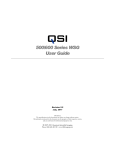
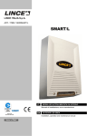
Alpy calibration User Guide Olivier Thizy ([email protected]) François Cochard ([email protected]) DC0018B : feb.2014 Alpy calibration module User Guide Olivier Thizy ([email protected]) François Cochard ([email protected]) February 2014 Ref. DC0018 - rev B Table of Contents Introduction 1 Discover your Alpy calibration module 1.1 Out of the box . . . . . . . . . . . . 1.2 Alpy calibration specifications . . . 1.3 Alpy calibration principle . . . . . 1.4 Power supply . . . . . . . . . . . . 1.5 Mechanical interfaces . . . . . . . 3 . . . . . 4 4 4 4 7 7 . . . . . . . . . . . . . . . . . . . . . . . . . . . . . . . . . . . . . . . . . . . . . . . . . . . . . . . . . . . . . . . . . . . . . . . . . . . . . . . . . . . . . . . . . . . . . . . . . . . . . . . . . . . . . . . . . . . . . . . . . . . . . . . . . . . . . . . . . . . . . . . . . . . . . . . . . . . . . . . . . . . . . . . . . . . . . . . 2 Using the calibration module 2.1 Testing the module . . . . . . . . . . . 2.1.1 Remote control . . . . . . . . . 2.1.2 Lamps lifetime saving function 2.2 Installing the Alpy calibration module 2.3 During observations . . . . . . . . . . . . . . . . . . . . . . . . . . . . . . . . . . . . . . . . . . . . . . . . . . . . . . . . . . . . . . . . . . . . . . . . . . . . . . . . . . . . . . . . . . . . . . . . . . . . . . . . . . . . . . . . . . . . . . . . . . . . . . . . . . . . . . . . . . . . . . . . . . . . . . . . . . . . . . . . . . . . . . . . . . . . . . . 8 . 8 . 9 . 9 . 9 . 10 3 Maintenance 12 3.1 Replacing the calibration lamp . . . . . . . . . . . . . . . . . . . . . . . . . . . . . . . . . . . . . . 12 3.2 Replacing the flat lamp . . . . . . . . . . . . . . . . . . . . . . . . . . . . . . . . . . . . . . . . . . . 13 2 Introduction Alpy is a family of modular elements for astronomical spectroscopy. The Alpy calibration module allows you to take quickly and simply, flat field and wavelength calibration images, manually or even remotely 1 . It also can be used to make offset and dark images, using a screen that blocks the light from the telescope. Equipment configuration The Alpy calibration module is specifically dedicated to the Alpy 600 spectroscope, and is optimized for use in combination with the Alpy guiding module. The Alpy calibration module can be used in various configurations, but we cannot doccument all of them ! In this document, we consider that you have an Alpy 600 and the Alpy guiding module and you’re already familiar with this instrument. You will find in the next chapters a presentation of the Alpy calibration module, how to install & tune it on the Alpy 600 and how to observe with it. Astronomical spectroscopy is a never ending story. We’ve thought about a lot of applications for the Alpy instrument (you can find some ideas on the Shelyak Instruments website 2 ). However, we know that you’ll invent new ones. We’ll be very happy to take your experiences into account to continuously improve this product : do not hesitate to contact us if you have any comments ! We invite you to join the growing Shelyak Instruments users and amateur spectroscopist community on the Spectro-L Yahoo group 3 and the Aras forum 4 to share your own experiences and ask questions to the community. We are really interested to see your results there. Enjoy Spectroscopy ! Olivier Thizy 5 François Cochard 6 1. 2. 3. 4. 5. 6. requires additional external 12V signals http://www.shelyak.com http://groups.yahoo.com/group/spectro-l/ http://www.spectro-aras.com/forum/ [email protected] [email protected] 3 1 Discover your Alpy calibration module 1.1 Out of the box When receiving your Alpy calibration module, you’ll find in the box the following parts: – The Alpy calibration module itself, – Four screws (M4x20mm) – An Allen wrench for attaching it to the Alpy guiding module. When the calibration module is activated, a screen masks the light beam coming from a telescope. This screen (positioned at 45°), is illuminated by the calibration lamp (or flat lamp) from the side: 1.2 Alpy calibration specifications Table 1.1 gives detailed specifications of Alpy Calibration. Figure 1.1 shows all dimensions. The Figure 1.2 gives the wavelength of main lines of the calibration lamp. 1.3 Alpy calibration principle Making accurate measurements in spectroscopy requires flat field and calibration images taken under the same conditions as the starlight. The principle of the Alpy calibration module is as follows: When deactivated, the light coming from the telescope goes directly to the spectroscope: 4 The screen has a black outer area and a central white reflecting area, which is designed to make a F/5 beam when used in combination with the Alpy guiding and Alpy 600 modules. CHAPTER 1. DISCOVER YOUR ALPY CALIBRATION MODULE Feature Value Unit Comment 100x95x30 mm see fig. 1.1 below Weight 300 g Power supply voltage 12 V Positive in the central pin. Power supply current 1 A max Power supply connector - - standard 5.5x2.5mm Dimensions Mechanical interface 4 screws + T-mount thread (M42x0.75mm) Table 1.1: Alpy calibration specifications Figure 1.1: Alpy calibration dimensions 5 Alpy calibration - User guide Figure 1.2: Main calibration lines 6 CHAPTER 1. DISCOVER YOUR ALPY CALIBRATION MODULE 1.5 Mechanical interfaces The Alpy calibration module is mounted on the Alpy guiding module with four M4 screws (see drawing 1.1). On both sides of the module, there is a standard Tmount thread (M42 x 0.75mm). When the screen is in place, you can switch on either the calibration light, the white halogen light (for flat field) or neither of them. In the last configuration, you can take offset or dark exposures - the screen prevents the starlight entering the spectroscope. The screen is activated by a servo-motor. When the calibration module is deactivated, the screen is moved out of the telescope beam, and has no effect on the light coming from the telescope. 1.4 Power supply The Alpy calibration module must be powered with 12V. The power supply socket is the central one: The connector is a standard 5.5 x 2.5mm, with the positive voltage on the central pin (outside is ground). The current is 1A max - It is the halogen lamp which is the main consumer (500mA). Of course, when the lights are switched off, the consumption of the module is only a few µA. The electronics include a voltage converter from 12V to 300V, to excite the Argon gas in the calibration lamp. The current is limited to few mA, but you must make sure the power supply is unpluggged before opening the calibration module. 7 2 Using the calibration module 2.1 Testing the module There are two switches on the Alpy calibration module. One is for calibration and the other for the flat field (halogen lamp). A LED indicates that the lamp is on. It will be useful when the Alpy calibration moduleis on the telescope: no light other than LED will be visible from outside. Plug in the power supply cable, and switch on the calibration lamp (left switch): Now, switch off the calibration lamp and switch on the flat lamp. This lamp is much brighter than the calibration one. The screen moves to the middle of the calibration module, and the calibration lamp is illuminated (the intensity is low - look directly at it, in a dark room). 8 CHAPTER 2. USING THE CALIBRATION MODULE The calibration lamp is close to the screen, to have maximum efficiency. The halogen lamp is on the side, to limit its intensity and prevent a too short exposure time. You can keep the screen in place and switch off both lights by activating both switches. In this configuration, both LEDs will flash slowly. When controlling the Alpy calibration module remotely, take care that the manual switches are OFF. 2.1.2 Lamps lifetime saving function The lamps (mainly the calibration one) have a limited lifetime. In normal conditions, it should be without significant effect, because the exposure time for calibration spectra is short (a few seconds each). But we know by experience that it is possible to forget to switch off the lamps at the end of the night... To protect the lamps, we’ve added a feature which automatically switches off the lamp after about 30 minutes. This also works for the flat lamp. When this happens, the corresponding LED flashes. You can simply switch off the lamp and switch it back on again immediately: it will be back on - for 30 minutes max. When one LED is flashing, the lamp has been switched off to protect the lamp’s lifetime. When both LEDs are flashing, the screen is across the telescope beam, but no lamp (calibration or flat) is on. This is useful for taking offset or dark images at night but a separate shutter is still required in full daylight. 2.1.1 Remote control Each switch is accompanied by a socket. The sockets are mechanically and electronically the same as the power supply one (12V, positive voltage on the central pin). Powering these connectors with 12V has the same effect as manually switching. It allows the Alpy calibration module to be controlled remotely. 2.2 Installing the Alpy calibration module This sections explains how to install the calibration module on the Alpy guiding module. Alternatively you can adapt the installation to your specific equipment. Remove the T-mount / 2” adapter from the Alpy guiding module: 9 Alpy calibration - User guide Attach the calibration module to the guiding module, with the four screws (included in the package). Position the calibration module in such a way that the black foam on the screen is towards the Alpy guiding module and the switches are at the opposite side to the guiding camera. Firmly tighten the four screws: Attach the T-mount / 2” adapter to the Alpy calibration module: The instrument is now ready for installation on the telescope (refer to the Alpy 600 and Alpy guiding user guides): 2.3 During observations Once the Alpy spectroscope (including the calibration module) is installed on the telescope, plug in the power supply (middle socket). When observing the stars, the calibration module has no effect on your instrument and images (the screen is outside the telescope light beam). When observing stars, both LEDs should be off. 10 CHAPTER 2. USING THE CALIBRATION MODULE Switch on the calibration lamp when you need to take calibration images. It can be done manually or remotely (see section 2.1.1). When the calibration lamp is on, the matching LED is on as well. Ensure the lamp is switched off at the end of your calibration exposures. – One LED is on: the matching lamp is on, and the screen is across the telescope beam. – Both LEDs are flashing: neither lamp is on, but the screen is across the telescope beam. – One LED is flashing: the matching lamp has been automatically switched off after 30 minutes, to preserve its lifetime. Just reset the matching switch to restart the normal behavior. Proceed in the same way for the flat lamp. Typical exposure times The exposure time depends on several parameters (CCD camera, equipment configuration..), but typical exposure times are: – 120 seconds for calibration – 10 seconds for flat field In any case, always make sure that your images are not saturated (refer to the Alpy 600 user guide). LEDs meaning - summary – Both LEDs are off : the calibration module is deactivated, the light beam coming from star is open. 11 3 Maintenance As with any lamps, the ones in Alpy Calibration have a limited lifetime. If you need to replace these lamps, proceed as below. We suggest removing the Alpy spectroscope from the telescope to do it, but is is not strictly required (if you have enough room around the calibration module to use a screwdriver). 3.1 Replacing the calibration lamp Before any maintenance on the calibration module, switch off any power supply (remove the plug). Loosen the two screws in the calibration lamp connector: Remove the screw in the middle of the cover, and loosen the other two: Replace the lamp. The lamp is asymmetric. Put it in the same position as below: Remove the cover: 12 CHAPTER 3. MAINTENANCE If you put the lamp in the opposite direction, it will apparently work, but the lifetime will be significantly shorter (it will become darker and darker over the time). Put back the cover, taking care of the servo cable: Unplug the servo cable: Tighten the three screws - that’s it. 3.2 Replacing the flat lamp Before any maintenance on the calibration module, switch off any power supply (remove the plug). Remove four screws around the module: Remove the screw in the middle of the cover, and loosen the other two: Gently slide the electronics from the calibration module body. Take care to protect the halogen lamp during this operation: Remove the cover: 13 Alpy calibration - User guide Remove the halogen lamp (rotate a quarter turn): Replace the lamp. Put back the electronics in the body. Tighten the four screws around the calibration module. Plug in the servo connector (take care of the orientation - refer to the circuit markings). Put back the cover, taking care of the servo cable: Tighten the three screws - that’s it. 14