1
SERVICE MANUAL
MODELS:
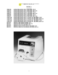
77310-00
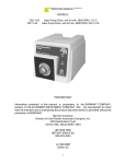
L/S Digi-Staltic Pump System for high performance precision tubing
115/230 VAC
77310-50
L/S Digi-Staltic Satellite Drive for high performance precision tubing
115/230 VAC
77340-00
L/S Digi-Staltic Pump System for precision tubing 115/230 VAC
77340-50
L/S Digi-Staltic Satellite Drive for precision tubing 115/230 VAC
77310-02
L/S Digi-Staltic Pump System Controller
77310-01
L/S Digi-Staltic Satellite Drive with no pump heads
77310-00 and 50 are supplied with two each 77200-62 pump heads
77340-00 and 50 are supplied with two each 77200-60 pump heads
PROPRIETARY
Information contained in this manual is proprietary to the BARNANT COMPANY,
division of COLE-PARMER INSTRUMENT COMPANY, INC. No reproduction for other
than the intended use of maintaining the product described herein is permitted without
the permission of BARNANT.
Barnant Company
Division of Cole-Parmer Instrument Company, Inc.
625 East Bunker Court
Vernon Hills, Illinois 60061-1844
(847) 549-7600
(847) 247-2929 (Fax)
800-323-4340
A-1299-0802
EDITION 02
1
TABLE OF CONTENTS
INTRODUCTION............................................................................................................. 2
SAFETY CONSIDERATIONS ........................................................................................ 4
FUNCTIONAL DESCRIPTION ....................................................................................... 5
DRIVE BOARD................................................................................................................ 6
CONTROLLER BOARD .................................................................................................. 8
TROUBLESHOOTING .................................................................................................. 10
REPAIR PROCEDURES.............................................................................................. 11
REPLACEMENT PARTS LISTING.............................................................................. 19
CHECK-OUT PROCEDURE ......................................................................................... 21
SPECIFICATIONS ........................................................................................................ 24
ACCESSORIES ............................................................................................................ 25
INTRODUCTION
2
Service for this product is performed at three levels: the customer,
distributor/COLE-PARMER and factory/depot repair. This manual describes distributor/COLE-PARMER service procedures.
Customer service procedures are described in the operator's manual. Customers
are encouraged to perform service as described in the operator's manual as well as in
special circumstances where special skills and safety are not considerations.
To use this manual, begin with the troubleshooting section to isolate the fault to a
replaceable part. The functional description and check-out procedure sections are also
helpful in determining the faulty part. Distributor/COLE-PARMER repair is limited to
replacement of modules as detailed in the replacement parts list section. The repair
procedures section details disassembly and assembly procedures. After repair, the
product should be calibrated and checked for proper performance.
Please refer to the operator's manual (A-1299-0780) for:
A) Applications Data
B) Product Description
C) Installation
D) Setup
E) Operation
F) User Calibration
G) User Troubleshooting & Maintenance
H) Accessories
I) Specifications
3
SAFETY CONSIDERATIONS
Servicing must be performed only by personnel trained and skilled in the
methods of troubleshooting and repair of electromechanical products.
Use of
procedures other than those described in this manual may result in a safety hazard to
service personnel and/or customers.
When servicing any component of this unit make absolutely sure that all power to
circuitry is removed. If any functional checks are to be performed while power is applied
and chassis is disassembled, care must be exercised for the following:
CAUTION:
Do not inadvertently short any part of the printed circuit card to
ground, as severe damage will result.
CAUTION:
Almost all circuits are referenced to the AC line. Powering the unit
from a isolation transformer is strongly recommended.
DANGER:
Never remove the cover from the pump drive when power is present.
AC and DC power in the pump drive can cause serious injury or
death. Ensure that the pump drive is disconnected from the power
source before removing the cover for maintenance. Allow ten
minutes for the capacitors in the power supply to discharge before
proceeding.
4
FUNCTIONAL DESCRIPTION
The Masterflex® dispenser, pump, and diluter system has two major components. A
tabletop control console provides means for operator programming and control. As
many as four satellite drives with two L/S® Easy-Load® II pump heads with tubing sets
provide the actual pumping action.
The control console is a basic I/O computer for operator interface and pump
coordination. The operator is guided through a series of menus to operate and to
program the unit. The LED backlit, two-row by-forty character, alphanumeric display
and four soft keys help the user through all the necessary control steps. A total of 20
membrane keys, including the numbers zero through nine, also facilitate the operator's
actions. An HC11-based microcontroller scans the keypad, communicates to the LCD
display module, and communicates with the attached satellite drives. The user’s
program information is stored indefinitely in an EEPROM. The pump powers the
control.
The controller communicates with the satellite drives via an RS232 port. The controller
is the master and hub of a star-configured system. The on-chip asynchronous serial
interface of the microcontroller is multiplexed to four RJ-12 phone jack ports on the
controller. TD (Transmit Data), RD (Receive Data), plus the control signal RTS
(Request To Send) are implemented in the controller and satellite drives. The controller
can broadcast system commands (for example, “go” and “stop”) to all the drives for
synchronization. The drives can request to be heard by the hub with RTS handshaking. A baud rate of 19200 is used.
The drives have an on/off switch and a seven-segment display. The seven segment
display indicates, when lit, power and numerically indicates the port from which its plug
into the controller. This RJ-12 port supplies power to, and RS-232 communication with,
the controller. The drives also have a DB-9 connector for remote start/stop input, and
two contact closure outputs. The pump systems are supplied with two L/S Easy Load II
pump heads. No operator controls other than the on/off switch and contact closure
switch are provided. The drives are driven by permanent magnet DC brush motors
using optical tachometer feedback for accurate speed control. The unit is dual (115/230
VAC) voltage. 115V line cord is supplied.
5
DRIVE BOARD
A. Input and Bus Voltage
B. PWM Motor Control Bridge
C. Dynamic Break Resistors
D. I/O and Earth Grounded Power Supply
E. 5V Switching Power Supply
F. Microprocessor and Encode/Decode Circuitry
A
B
D
E
6
C
F
7
CONTROLLER BOARD
A. RS-232 Motor Drive Interface
B. RS-232 Balance Interface
C. RS-232 Computer Interface
D. Display Interface and power
E. Buzzer
F. Keypad connector
G. Microprocessor, Memory, and DUART for computer & balance interface
H. 5V Switching Power Supply
B
A
C
D
E
F
G
8
H
9
TROUBLESHOOTING
Repairs on this unit are confined to the unit’s drive and controller PC Board,
and/or drive motor assembly.
Where possible, swap known good parts to localize and isolate the problem. The
following is a list of possible problems and remedies:
VERIFY AC POWER IS OPERATIVE.
UNIT DOES NOT TURN ON; NO SEVEN SEGMENT DISPLAY:
1.
2.
3.
4.
fuse blown
power cord not connected properly
A/C power switch failure
unit connected to dead outlet
-replace fuse
-check & replace
-replace switch assembly
-verify supply is HOT
UNIT BLOWS FUSES:
1. wrong voltage selection
2. motor drive failure
3. defective drive board
4. wrong fuse installed
-check proper voltage switch position
-check using known good motor
-return/replace drive board
-check fuse type and rating
DRIVE UNIT DISPLAY “0”
1. RJ12 cable not connected
properly
2. controller RJ12 port is defective
-check/replace cable
-try another pump #/
replace controller board
MOTOR WILL NOT RUN, DRIVE UNIT DISPLAYS A PUMP #:
1. defective keypad
2 defective drive board
3. defective encoder
-return/replace keypad
-return/replace drive board
-return/replace motor assembly
NO REMOTE OPERATION:
1. defective controller board
2. external cable not connected
properly
-return/replace controller board
-check/replace cable
FOR ADDITIONAL INFORMATION REGARDING YOUR UNIT PLEASE REFER
TO THE FOLLOWING:
A-1299-0780 Operator's Manual
10
REPAIR PROCEDURES
DISPLAYED ERROR CODES
COMMUNICATIONS ERRORS
ERROR!
ENTER CONTINUES
COMMUNICATION ERROR #?
? = 1,2,3...
1 = checksum error
2 = framing error
3 = overrun error
4 = invalid command
5 = invalid data
6 = incomplete command string
10 = no reply from pump drive
11 = reply command didn't match request command
12 = calculated checksum didn't match rx checksum
DRIVE ERRORS
1).
ERROR!
ENTER CONTINUES
DRIVE STOPPED BY TIMEOUT
1.) drive cable to controller disconnected/bad
2.) defective drive board
3.) defective controller board
2)
ERROR!
ENTER CONTINUES
NO ENCODER PULSES
1.) encoder cable disconnected/bad
2.) defective drive board
3.) defective motor encoder assembly
3)
-replace/reattach cable
-replace drive board
-replace motor assembly
ERROR!
ENTER CONTINUES
MOTOR OVER SPEED
1.) defective drive board
4)
-replace/reattach cable
-replace drive board
-replace controller board
-replace drive board
ERROR!
ENTER CONTINUES
MOTOR CONTROL FAULT
11
1.) Voltage selection switch set to improper voltage
5)
ERROR!
ENTER CONTINUES
MOTOR OVER CURRENT LIMIT
1.) Current limit is being exceeded.
6)
-Check pump and/or motor
drive system for binding.
Check with a known good
motor.
ERROR!
ENTER CONTINUES
BUS VOLTAGE LIMIT
1.) Voltage limit is being exceeded.
7)
-Check AC supply voltage.
ERROR!
ENTER CONTINUES
CANNOT COMMUNICATE WITH BALANCE
1.) Wrong balance
2.) Port isn’t working
3.) Balance isn’t setup and wired correctly.
4.) External cable not connected properly.
8)
-use approved balances
-replace controller board
-check balance owners
manual
-check/replace cable
ERROR!
ENTER CONTINUES
BAD EEPROM WRITE, DATA NOT SAVE
1.) The controller couldn’t write to the EEPROM.
9)
-Check voltage selection
switch for proper voltage.
-replace controller board
ERROR!
ENTER CONTINUES
UNKOWN ERROR CODE
An error unknown to the controller has occurred.
-return unit
DANGER: Never remove the cover from the pump drive when power is present.
AC and DC power in the pump drive can cause serious injury or death.
Ensure that the pump drive is disconnected from the power source
before removing the cover for maintenance. Allow ten minutes for the
capacitors in the power supply to discharge before proceeding.
TO DISASSEMBLE DRIVE UNIT, PROCEED AS FOLLOWS:
12
A) Disconnect AC power.
B) Remove and retain the four screws from each side of the pump drive cover.
C) Remove the cover by sliding it straight up.
TO REASSEMBLE DRIVE UNIT, PROCEED AS FOLLOWS:
A) Slide on cover.
B) Install the four pan head screws on each side of the unit's cover.
TO REMOVE PCB STACK ASSEMBLY:
A)
B)
C)
D)
E)
F)
Remove fuse.
Remove the two pan head screws on the I/O panel at the rear of the chassis.
Remove the four screws from the lower printed circuit board.
Remove PCB Stack Assembly.
To remove PCB slide it forward and lift up.
Remove all cables and wires from PCB.
TO REPLACE PCB STACK ASSEMBLY:
A) Follow the steps outlined in "DISASSEMBLE DRIVE UNIT".
B) Replace PCB Stack assembly.
C) Note wiring of chassis as follows:
1) WHITE of AC power switch to: J6
2) BLACK of AC power switch to: J5
3) RED of drive motor to: M1
4) BLACK of drive motor to: M2
5) GREEN/YELLOW of chassis ground to: J4
6) Ribbon cable from Display PCB J1
7) Cable from Motor Encoder J2
D) Follow the steps outlined in "ASSEMBLE DRIVE UNIT".
TO REMOVE SEVEN SEGMENT DISPLAY PCB:
A) Follow the steps outlined in "DISASSEMBLE DRIVE UNIT".
B) Remove the two nuts/washers holding the PCB to the chassis.
C) Remove ribbon cable.
13
TO REPLACE SEVEN SEGMENT DISPLAY PCB:
A) Follow the steps outlined in "DISASSEMBLE DRIVE UNIT".
B) Replace cables.
1) Cable from PCB Stack assembly J1.
C) Secure Display PCB with two nuts/washers.
D) Follow the steps outlined in "ASSEMBLE DRIVE UNIT".
TO REMOVE BELT:
A). Follow the steps outlined in "DISASSEMBLE DRIVE UNIT".
B). Refer to Figure 7 and loosen, but do not remove, the two nuts that secure the motor
to the top of the motor mounting brackets.
NOTE: Be careful when working near the fan end of the motor. The fan blades are
sharp.
C) Pivot the motor toward the pump, and remove the belt from around the motor pulley.
D) Remove the belt from around the pump pulley.
TO REPLACE BELT:
A). Install the replacement belt around the pump pulley and around the motor pulley.
B). Pivot the motor so the belt is taut, and secure the motor in position by tightening the
loosened nuts, loosened just enough to hold the motor.
C). Test belt tension by pressing on the belt midway between the pulley.
The belt should flex approximately 1/8 in. (3 mm).
D). If belt tension is correct, tighten the nuts securely. If tension is not correct, loosen
the nuts and repeat.
E). Follow the steps outlined in "ASSEMBLE DRIVE UNIT".
TO REPLACE BELT:
NOTE: Inspect the belt to see if it is broken or has missing teeth. If it is broken or worn,
it needs to be replaced.
A) Refer to Figure 7 and loosen, but do not remove, the two nuts that secure the motor
to the top of the motor mounting brackets.
14
15
Brush Replacement
Exact motor brush and commutator life will depend on duty cycle and motor operating
speed. Inspect the brushes every six months or after 2000 hours of operation,
whichever occurs first. Replace brushes if they are less than 0.30 in (7.6 mm) long.
Inspect the commutator when the brushes are replaced, and clean if necessary.
DANGER: Never remove the cover from the pump drive when power is present.
AC and DC power in the pump drive can cause serious injury or death. Ensure
that the pump drive is disconnected from the power source before removing the
cover for maintenance. Allow ten minutes for the capacitors in the power supply
to discharge before proceeding.
A) Refer to Belt Replacement, remove the cover, and remove the belt from the pulley on
the drive motor.
B) Pivot the motor away from the pump to gain access to the brush on the pump side of
the motor.
C) Refer to Figure 8 and remove the brush caps.
D) Rotate each brush retainer so it lines up with the groove in the brush holder.
Remove the brushes.
E) Measure the length of the brushes. If either brush is less than 0.30 in (7.6 mm) long,
they both need to be replaced. Always replace them in pairs.
CAUTION: Excessive commutator wear or “bridging” between commutator
segments can cause excessive current through the controller circuit and damage
to the dispenser.
F) Inspect the commutator for wear and dirt. If the commutator segments are worn,
replace the motor. If there are dark tracks where the brushes contact the
commutator, clean with isopropyl alcohol.
G) Install the brushes into the brush holders and rotate the retainer to secure the
brushes. Reinstall the brush caps.
H) When the motor has been reassembled, refer to Belt Replacement to reassemble the
pump drive.
16
TO DISASSEMBLE CONTROLLER UNIT, PROCEED AS FOLLOWS:
A) Disconnect AC power.
B) Remove and retain the four screws from the under side of the controller.
C) Remove the cover by sliding it straight up.
TO REMOVE DISPLAY PCB:
A) Follow the steps outlined in "DISASSEMBLE CONTROLLER UNIT".
B) Remove the four screws holding the PCB to the cover.
C) Remove cables.
TO REPLACE DISPLAY PCB:
A) Follow the steps outlined in "DISASSEMBLE CONTROLLER UNIT".
B) Replace the cable.
1) Cable from PCB J5.
2) Cable to PCB J6.
C) Secure Display PCB with four screws.
D) Follow the steps outlined in "ASSEMBLE CONTROLLER UNIT".
17
TO REMOVE KEYPAD:
A)
B)
C)
D)
Follow the steps outlined in "DISASSEMBLE CONTROLLER UNIT".
Remove cable from PCB J7.
Peel keypad from enclosure.
Affix new keypad to enclosure.
TO REMOVE PCB ASSEMBLY:
A) Remove the four screws from the printed circuit board.
B) Remove PCB Assembly.
C) Remove all cables and wires from PCB.
TO REPLACE PCB ASSEMBLY:
A) Follow the steps outlined in "DISASSEMBLE CONTROLLER UNIT".
B) Replace PCB assembly.
C) Note wiring of chassis as follows:
1) RED and BLACK of Display PCB to: J6
2) Ribbon cable of Display PCB to J5
3) Cable of keypad to J7
D) Follow the steps outlined in "ASSEMBLE CONTROLLER UNIT".
18
REPLACEMENT PARTS LISTING
The following is a list of stockable main control PCB assemblies and their reference
schematic diagrams for all indicated models:
MODELS
MODEL #
PCB #
77310-00
E-2429-0003
E-2323-0001
REFERENCE
SCHEMATIC
E-2306
E-2321
77310-50
E-2429-0003
E-2323-0001
E-2306
E-2321
77340-00
E-2429-0003
E-2323-0001
E-2306
E-2321
77340-50
E-2429-0003
E-2323-0001
E-2306
E-2321
77310-02
E-2323-0001
E-2321
77310-01
E-2429-0003
E-2306
OTHER REPLACEABLE PARTS
Description
Part Number
19
Line cord
115V
Line cord
230V
AC Receptacle
3-1/2 ft (1.1 m) RJ-12 cable
Seven Segment Display Assembly
Keypad (Controller)
Bearing Block Assembly
ON/OFF Switch
Belt
Small Belt Pulley
Large Belt Pulley
Motor Assembly
Motor brushes (2)
Fuse
Rubber feet (each)
B-3115
B-2938
B-4016
77095-02
B-3889-CR
E-2534
D-3115-CR
B-1084-0121
A-1341-0006
A-3166
B-2317
D-3106-0001
B-1238-0056
B-1115-0043
A-1390-0004
20
CHECK-OUT PROCEDURE
0.00 Test equipment required:
0.01 Hand-Tach
0.02 Line leakage tester
0.03 Hi-pot tester
0.04 DB9 Communication Jumper cable
0.05 RJ12 Cable
0.06 Dispensing Wand (77310-05) or Foot switch (07595-40)
0.06 Voltmeter
0.08 Test Unit:
77310-02 Only: 77310-01 Test Drive
77310-01 Only: 77310-02 Test Controller
2.00 Performance:
CAUTION:
HIGH VOLTAGE IS PRESENT ON CONNECTORS AND PCB!
A. OPERATION
1. a. Switch the voltage selector switch to the proper voltage and plug in the
drive.
b. Plug the RJ-12 cable into the rear of the controller (77310-02) labeled
Pump 1 (2,3,4) and the other end into the rear of the drive (77310-01).
c. Plug a jumper cable into the Balance (DB9) to the PC (DB9) ports of the
controller (77310-02) linking them together.
B.
While holding the upper left arrow key on the controller switch the main power on
one of the connected drives. Release the arrow key and turn on any remaining
drives. Verify that the display number displays “0” for 3 seconds then “8” for 3
seconds, then the drive should display the appropriate pump number. The controller
display should display the appropriate drive type DIGI . For Example, if there was
only 1 pump (77310-01 plugged into the controller “Pump #1 location”, the display on
the controller should display the following:
21
#1:DIGI
KEYPAD
#2:NONE
#3:NONE
RPM
#4:NONE
DISPLAY
COM: PASS
ERASE
CONTROLLER (Drive Only: Proceed to Step 7)
2.
77310-02 only: If only one drive is being used, leave the drive on and remove
RJ12 cable from the Pump1 location and repeat on RJ12 ports Pump 2, Pump 3,
and Pump 4. Verify the drive's seven-segment display shows “8” then the correct
number for each RJ12 pump port and that the controller reports the proper drive.
COM should have a “PASS” indicating the Balance and PC COM ports are
operating correctly. If there is a failure “FAIL” will be displayed.
3.
77310-02 only: Activate the KEYPAD test by pressing the arrow just below
“KEYPAD”. Then press each key and verify the key was pressed by observing the
controllers display. Press the cancel/stop button twice to exit keypad test.
PRESS EACH KEY ONCE
UP ARROW 1
PRESS CANCEL
TWICE TO EXIT
4.
77310-02 only: Activate the DISPLAY test by pressing the arrow just below
“DISPLAY”. All segments should fill in.
5.
77310-02 only: Activate the ERASE by pressing the arrow just below “ERASE”.
This will erase any programs in memory.
DRIVE
6.
77310-01 only: Activate the RPM test by pressing the arrow just below “RPM”. The
controller display should show 600 for each of the drives connected. Attach a
dispensing wand to the drive unit DB9 port. Then activate the auxiliary switch on
the dispensing wand and the drive should start. If a drive isn’t connected or there
is a problem with the drive an error code will be displayed.
22
CODES:
NONE = No response from drive (Drive not connected or not communicating)
ER5 = Timeout
ER6 = No encoder pulses
ER7 = Excessive encoder pulses
ER8 = Incorrect motor response
ER9 = Motor current error
ERA = Bus voltage error
7.
Using a hand-tach verify that the connected drives are running at 600 +/- 1 RPM.
Release the dispense wand switch and motor should stop.
8.
Enter exits the RPM mode. (Drive Only: Proceed to Step 12)
9.
Turn OFF drive/drives.
10.
Turn drive/drives ON and verify that there are no error messages.
11.
Turn drive/drives OFF and unplug and disconnect controller.
3.0 Safety:
A. HI-POT TEST
With a sensitivity setting of 5 mA, apply 1900 VDC (77310-01 only), Hot
lead Black to Ground, for 60 sec.
B. LINE LEAKAGE TEST (.5mA MAX.)
C. GROUND RESISTANCE TEST (.5 ohms MAX.)
23
SPECIFICATIONS
Output:
Speed:
Maximum torque output:
Speed regulation (all conditions):
Remote contact closures:
Dispense volume:
Dilute volume:
6 to 600 rpm
12.9 kg•cm (180 oz-in)
±0.3% of full speed
28 VDC, 1 A
28 VAC, 1 A
0.1 mL to 8000 L
Sample: 0.1 mL to 100.0 mL
Delivery: 0.1 mL to 8000 L
Input:
Supply voltage limits:
115 VAC
230 VAC
Nominal current:
115 VAC
230 VAC
90 VAC to 130 VAC, 48 Hz to 63 Hz
180 VAC to 260 VAC, 48 Hz to 63 Hz
1.7 A
0.8 A
Installation category:
Category II per IEC 664 (Local level —
appliances, portable equipment, etc.)
Remote input:
START/STOP +5 VDC, 5 mA
Display:
40-character x 2-line backlit LCD
Construction:
Control console dimensions:
Pump drive weight:
22.6 cm (8.9 in) wide
16.5 cm (6.5 in) deep
2.3 cm (0.9 in) front, 6.9 cm (2.7 in) back in height
1.4 kg (3.0 lbs)
23.4 cm (9.2 in) wide
32.3 cm (12.7 in) deep
18.8 cm (7.4 in) high
9.1 kg (20 lbs)
Two EASY-LOAD II pump heads:
14.6 cm (5.75 in) deep
Control console weight:
Pump drive dimensions:
Environment:
Operating temperature:
Storage temperature:
Humidity (non-condensing):
Altitude:
Pollution degree:
0° to 40°C (32° to 104°F)
−25° to 65°C (−13° to 149°F)
10% to 90%
Less than 2000 m (6500 ft)
Pollution degree 2 per IEC 664
(Indoor use — lab, office)
All materials withstand standard cleaning
solvents. Materials used in the construction
are: a polyester label, a combined aluminum
motor and paint-loc steel controller enclosure,
and an epoxy-based, non-chip paint finish.
Chemical resistance:
Environmental protection:
Withstands general spills and light sprays
(IEC-529 IP22).
Compliance:
Meets UL 508;
CSA C22.2 No. 14-M91; and
24
CE
ACCESSORIES
25
EN61010-1/A2: 1995 (Safety),
EN50081-1: 1992 (EMC Emissions), and
EN50082-1: 1992 (EMC Immunity)
Description
10 ft (3 m) RJ-12 cable
15 ft (4.6 m) RJ-12 cable
Footswitch
Dispenser handle for 1 to 4 pumps
Dispenser handle holder, small V-base
Dispenser handle holder, large V-base
PTFE tubing weights
Glass dispensing tip w/Luer lock for 3/16 in. and 1/4 in. ID tubing
EASY-LOAD II pump head for high performance precision tubing
EASY-LOAD II pump head for precision tubing
Mounting hardware (2) pump heads
“Y” connectors for use with L/S tubing size:
L/S ® 13, L/S ® 14 10/pk (KYNAR ® )
L/S ® 16 20/pk (Polypropylene)
L/S ® 15, L/S ® 25 20/pk (Polypropylene)
L/S ® 17, L/S ® 24 20/pk (Polypropylene)
L/S ® 18, L/S ® 35, L/S ® 36 20/pk (Polypropylene)
Stands
Frame rods (small)
Frame rods (large)
Equipment clamp (small)
Equipment clamp (large)
Frame clamp
V-Base (small)
V-Base (large)
26
Part Number
77095-03
77095-04
07595-40
77310-05
08024-55
08024-56
77310-03
77310-04
77200-62
77200-60
77200-02
30703-90
06295-10
06295-20
06295-30
06295-40
08024-22
08024-23
08024-40
08024-41
08024-28
08024-55
08024-56