1
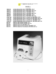
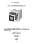
****SERVICE MANUAL**** 77096-00 77096-05 877-9600 877-9605 Liqui-Sense Controller 115V units Liqui-Sense Controller 230V units Liquid-Sensor Controller 115V units Liquid-Sensor Controller 230V units PROPRIETARY Information contained in this manual is proprietary to the Barnant Company, division of ColeParmer Instrument Company, Inc. No reproduction for other than the intended use of maintaining the product described herein is permitted without the permission of Barnant. Barnant Company Division of Cole-Parmer Instrument Company, Inc. 625 East Bunker Court Vernon Hills, Illinois 60061-1844 (847)549-7600 (847) 247-2929 (Fax) 800-323-4340 A-1299-0511 Edition 02 TABLE OF CONTENTS PAGE 1. INTRODUCTION ...............................................................................................................3 2. SAFETY CONSIDERATIONS...........................................................................................3 3. FUNCTIONAL DESCRIPTION .........................................................................................3 4. TROUBLESHOOTING.......................................................................................................3 5. REPAIR PROCEDURES ....................................................................................................4 6. REPLACEMENT PARTS ...................................................................................................5 7. CALIBRATION PROCEDURE..........................................................................................5 8. FUNCTIONAL TEST .........................................................................................................5 3 1. INTRODUCTION This manual is for service performed at the distributor level. Customer service procedures are described in the Operator Manual. Customers are encouraged to perform service as described in the Operator Manual as well as in special circumstances where special skills and safety are not considerations. To use this manual begin with the troubleshooting section to isolate the fault to a replaceable part. The Functional Description and Check-out Procedure Sections are also helpful in determining the faulty part. Dealer repair is limited to replacement of modules as detailed in the REPLACEMENT PARTS LIST section. The REPAIR PROCEDURES SECTION details disassembly and assembly procedures. After repair, the product should be calibrated and checked for proper performance. Please refer to the appropriate Operator Manual P/N A-1299-0512 for: APPLICATION DATA PRODUCT DESCRIPTION INSTALLATION SETUP OPERATION USER CALIBRATION USER TROUBLESHOOTING & MAINTENANCE ACCESSORIES 2. SAFETY CONSIDERATIONS Power should be connected only to a grounded outlet. Check power cord for frayed wear or exposed conductors. Replace with a new power cord if these conditions are found. Check that proper power level is available to supply the instrument. 3. FUNCTIONAL DESCRIPTION The function of the Liqui-Sense controller is to monitor various sensor types and when a fault condition occurs, to deactivate the main output, activate the auxiliary output, and signal an audible and visual alarm. The sensitivity of detection is adjustable by means of a front panel trimpot. 4. TROUBLESHOOTING Troubleshooting should be done to isolate to which channel (1 or 2) there is a problem or to a back panel connection problem. Equipment on hand to test the unit should include: 4 1 - known good cable and sensor pad 1 - digital voltmeter 1 - jumper for simulating conduct closure Test - Channel 1 and 2 1. 2. 3. 4. 5. 6. 7. 8. 9. Power up unit. Connect sensor pad and cable to channel 1. Unit should be in a non-alarm state. Put a few drops of water on the sensor pad. The alarm should go on (alarm SW is on and LED, DS2, is on). Power should now be applied to “Aux Power Output.” There should be no power to “Main Power Output.” If this is not the case then the safety output circuit is not working and the board should be replaced. Repeat above steps for channel 2. With the unit in non-alarm state use the jumper to short out the external contact closure for channel 1. The alarm should sound and the power transfer from main to auxiliary as above. Repeat the test for channel 2. When the jumper is removed the unit should return to non-alarm state. Replace the circuit board is any of the tests fail. Connect an ohm meter across the contact closure. The contact should be open on non-alarm conditions and closed on alarm conditions. Replace the circuit board if the condition is not met. Test switch. When the test switch is pressed it simulates a fault condition. The power should transfer from main to auxiliary output. The contact closure should close and the alarm will sound. Releasing the switch removes the fault condition. If the test fails replace the circuit board. 5. REPAIR PROCEDURES 1. To remove the circuit board from the case disconnect power first. 2. Turn unit over so the underside is facing up. Remove the screws holding the cover, and then remove the cover. 3. Make note of all the jumpers and how they are attached to the board. Remove the jumper connections. 4. Remove the screws holding the circuit board to the case. 5. Remove the old circuit board and install the new one. 6. Replace the screws holding the circuit board to the case. 7. Reinstall the jumpers as noted in step 3. CAUTION: Failure to reinstall the jumpers correctly could destroy the new circuit board. 8. Replace the cover and attach it with the screws removed in step 2. 6. REPLACEMENT PARTS DESCRIPTION 5 PART NUMBER 115 VOLT UNITS 77096-00 CIRCUIT BOARD D-2808-0001 877-9600 FUSE 10 AMP B-1115-0052 LINE CORD B-3384-0001 77096-05 CIRCUIT BOARD D-2808-0002 877-9605 FUSE 6.3 AMP (20mm) B-1115-0054 LINE CORD (EUROPEAN) B-2938 230 VOLT UNITS 7. CALIBRATION PROCEDURE Follow CAL-1593 to calibrate the new circuit board installed in the unit. 8. FUNCTIONAL TEST Follow CAL-1592 to test unit. 6