1
Next
Go To Table Of Contents
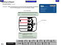
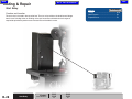
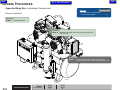
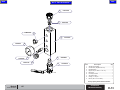
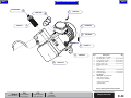
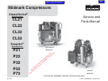
Midmark Compressors
ClassicSeries®
Model Numbers:
Service and
Parts Manual
CL21
CL22
CL32
CL52
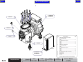
PowerAir®
Model Numbers:
ClassicSeries®
P21
P22
P32
P52
P72
Model CL32
S
c
ON odu
I
r
T p
UC this
D
O or
PR le f
IN b
R aila
E
av
NG be
O
L ot
O yn
N
a
els s m
d
t
o ar
eM ep
m c
So ervi
es
om
t.
PowerAir®
Model P22
FOR USE BY MIDMARK TRAINED TECHNICIANS ONLY
SF-1899
Style B
Part No. 10540900 Rev.B (5/20/2015)
Back
Section C
Symbols .................................... iii
Ordering Parts ......................... iii
Serial Number Location .......... iii
Specifications ........................... iv / v
Model Identification /
Compliance Charts .................. vi
Warranty Information............... vii
ACCESS PROCEDURES
Section D
GENERAL INFORMATION
WIRING DIAGRAMS
OPERATION &
TROUBLESHOOTING
Compression Cycle ................. A-2
Purge Cycle .............................. A-4
COMPONENT TESTING
Pressure Switch ....................... B-2
Intake Filter ............................... B-8
Checking for Leaks .................. B-11
Coalescing Filter ...................... B-12
Solenoid .................................... B-13
Desiccant Tank .......................... B-16
Low Voltage ............................... B-17
Capacitor ................................... B-20
Check Valve .............................. B-22
ON/OFF Switch ......................... B-24
Fuse ........................................... B-26
(Lubricated Only)
Start Relay ................................ B-28
Compressor Heads(Listed by Model)
CL21, CL22, CL32, CL52, CL72.B-30
P21, P22, P32 ............................. B-32
P52, P72 ..................................... B-33
Purge Valve ............................... B-35
(Oil-Less Only)
Thermal Overload Switch ........ B-37
(Oil-Less with Quiet Cover Only)
Fan ............................................. B-39
Check Valve ........................ C-2
Electrical Box Cover .......... C-3
Only Models CL21, CL22, CL32
CL52
Capacitor/Relay Box ........... C-4
Compressor Head
Electrical Cover .................. C-5
Only Models P21, P22, P32, P52,
P72
Sound Cover Electrical
Box (accessory) ................. C-6
Click GO TO PAGE:
button (then enter
desired page number)
to view any page in this
document.
Go To Page:
ClassicSeries® Models
(Lubricated)
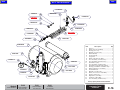
CL21 ................................. D-2
CL22.................................. D-5
CL32.................................. D-8
CL52.................................. D-11
PowerAir® Models
(Oil-Less)
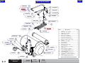
P21 .................................... D-14
P22 .................................... D-17
P32 .................................... D-20
P52 .................................... D-23
P72 .................................... D-26
Section E
Section B
Section A
General
Information
Table Of Contents
Next
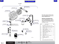
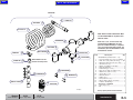
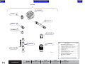
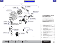
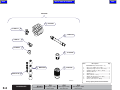
EXPLODED VIEWS / PARTS LISTS
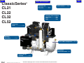
ClassicSeries® Models
(Lubricated)
CL21, CL22, CL32, CL52 .... E-2*
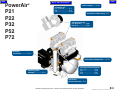
PowerAir® Models
(Oil-Less)
P21, P22, P32, P52, P72, ..... E-3*
* Indicates multiple pages due to model / serial number break(s)
General Information
Back
Next
Go To Table Of Contents
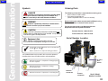
Symbols
DANGER
Indicates an imminently hazardous situation which
will result in serious or fatal injury if not avoided. This
symbol is used only in the most extreme conditions.
WARNING
Indicates a potentially hazardous situation which
could result in serious injury if not avoided.
CAUTION
Indicates a potentially hazardous situation which may
result in minor or moderate injury if not avoided. It may also be
used to alert against unsafe practices.
Equipment Alert
General Information
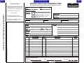
Ordering Parts
The following information is required when ordering parts:
• Serial number & model number
• Part number for desired part.
[Refer to Exploded Views / Parts Lists section]
Non-warranty parts orders may be faxed to Midmark using
the Fax Order Form in the back of this manual.
For warranty parts orders, call Midmark's Service
Department with the required information.
Customer Service: 1-800-643-6275
Technical Service: 1-888-279-1260
Serial Number Location
Indicates a potentially hazardous situation
which could result in equipment damage if not avoided.
In Section A, test the components in the order indicated.
(ex. 1st then, 2nd )
Refer to Section B for component testing procedures.
The symbols below may be used in this manual to represent
the operational status of table functions and components.
10 Gallon
Tank
Models
Indicates the function / component is working properly.
No action required.
Indicates the function / component is working,
but a problem exists.
Indicates the function / component is not working at all.
AA195900
20 Gallon
Tank Models
32 Gallon
Tank Models
Serial / Model
Number Location
iii
© Midmark Corporation 2007 SF-1899
Back
Next
Go To Table Of Contents
General Information
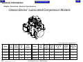
Weights, Dimensions, Electrical Specifications
®
ClassicSeries Lubricated Compressor Models
Classifications: Class 1, No Applied Part
iv
Model
# of
Users
CFM @
80 PSI
Total
HP
Tank
Capacity
Voltage
Total
Amps
Breaker
Size
(Amps)
Sound
Level
(dbA)
Dimensions
HxWxD
(IN.)
Product
Weight
(lbs.)
Fresh Air
Intake Pipe
Size
CL21
1-3
5.3
1.0
10
115
12.4
20
68
29 x 26 x 24
202
2"
CL22
1-3
5.3
1.0
10
208-230
6
20
68
29 x 26 x 24
202
2"
CL32
3-5
10.6
2.0
20
208-230
12
20
71
31 x 33 x 26
329
2"
CL52
5-7
15.9
3.0
32
208-230
18
30
75
32 x 41 x 27
460
2"
www.Midmark.com • 1-800-Midmark
© Midmark Corporation 2007 SF-1899
Back
Next
Go To Table Of Contents
General Information
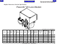
Weights, Dimensions, Electrical Specifications
®
PowerAir Oil-Less Models
Classifications: Class 1, No Applied Part
Sound Level
(dBA) With
Quiet Cover
Dimensions
HxWxD
(IN.)
Dimensions
With Sound
Cover
HxWxD
(IN.)
Product
Weight
(LBS.)
Fresh Air
Intake
Pipe
Size
Voltage
Total
Amps
Breaker
Size
Sound
Level
(dBA)
10
115
16.0
20
65
60
27 x 26 x 24
32 x 26 x 25
225
2"
1.5
10
208-230
7.0
20
65
60
27 x 26 x 24
32 x 26 x 25
225
2"
7.8
2.25
20
208-230
11.0
20
67
62
29 x 33 x 26
33 x 33 x 28
295
2"
5-7
10.6
3.2
20
208-230
20.0
30
70
65
31 x 33 x 26
33 x 33 x 28
345
2"
7 - 10
15.9
4.8
32
208-230
29.0
40
73
68
33 x 40 x 27
39 x 40 x 30
425
2"
Model
#
Users
CFM @
80 PSI
Total
HP
Tank
Capacity
P21
1-3
5.2
1.5
P22
1-3
5.2
P32
3-5
P52
P72
v
www.Midmark.com • 1-800-Midmark
© Midmark Corporation 2007 SF-1899
Back
General Information
Next
Go To Table Of Contents
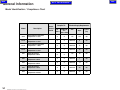
Model Identification / Compliance Chart
Model
vi
Description
Serial
Number
Prefix
Complies To:
UL
60601-1
CAN/CSA
22.2,
#601.1-M90
Electrical Supply Requirements:
VAC
Amps
Cycles
(Hz)
CL21
ClassicSeries Lubricated
Compressor 3 User
x
x
115
12.4
60
CL22
ClassicSeries Lubricated
Compressor 3 User
x
x
208-230
6
60
CL32
ClassicSeries Lubricated
Compressor 5 User
x
x
208-230
12
60
CL52
ClassicSeries Lubricated
Compressor 7 User
x
x
208-230
18
60
P21
PowerAir Oil-Less
Compressor 3 User
x
x
115
16
60
P22
PowerAir Oil-Less
Compressor 3 User
x
x
208-230
7
60
P32
PowerAir Oil-Less
Compressor 5 User
x
x
208-230
11
60
P22
PowerAir Oil-Less
Compressor 7 User
x
x
208-230
20
60
P72
PowerAir Oil-Less
Compressor 10 User
x
x
208-230
29
60
© Midmark Corporation 2007 SF-1899 Rev 11/07
Back
Go To Table Of Contents
Next
General Information
Warranty Information
LIMITED WARRANTY
Midmark Corporation (“Midmark”) warrants to the original purchaser its new ClassicSeries® and PowerAir® products and
components (except for components not warranted under “Exclusions”) manufactured by Midmark to be free from defects in
material and workmanship under normal use and service. Midmark’s obligation under this warranty is limited to the repair or
replacement, at Midmark’s option, of the parts or the products the defects of which are reported to Midmark within the
applicable warranty period and which, upon examination by Midmark, prove to be defective.
APPLICABLE WARRANTY PERIOD
The applicable warranty period, measured from the date of installation for the original user, shall be:
• ClassicSeries® Lubricated Compressors: Two (2) years or 1,500 usage hours (whichever comes first)
• PowerAir® Oil-less Compressors: Five (5) years or 3,500 usage hours (whichever comes first)
EXCLUSIONS
This warranty does not cover and Midmark shall not be liable for the following: (1) repairs and replacements because of
misuse, abuse, negligence, alteration, accident, freight damage, or tampering; (2) products which are not installed, used,
and properly cleaned as required in the Midmark “Installation” manual and or “maintenance” guide for this applicable
product; (3) products considered to be of a consumable nature; (4) accessories or parts not manufactured by Midmark; (5)
charges by anyone for adjustments, repairs, replacement parts, installation, or other work performed upon or in connection
with such products which is not expressly authorized in writing in advance by Midmark.
EXCLUSIVE REMEDY
Midmark’s only obligation under this warranty is the repair or replacement of defective parts. Midmark shall not be liable for
any direct, special, indirect, incidental, exemplary, or consequential damages or delay, including, but not limited to,
damages for loss of profits or loss of use.
NO AUTHORIZATION
No person or firm is authorized to create for Midmark any other obligation or liability in connection with the products.
THIS WARRANTY IS MIDMARK’S ONLY WARRANTY AND IS IN LIEU OF ALL OTHER WARRANTIES, EXPRESS OR
IMPLIED. MIDMARK MAKES NO IMPLIED WARRANTIES OF ANY KIND INCLUDING ANY WARRANTIES OF
MERCHANTABILITY OR FITNESS FOR ANY PARTICULAR PURPOSE. THIS WARRANTY IS LIMITED TO THE
REPAIR OR REPLACEMENT OF DEFECTIVE PARTS.
vii
© Midmark Corporation 2007 SF-1899
Back
Next
Go To Table Of Contents
Section A
Troubleshooting
Go To Page
Page:
Function / System
Compression Cycle ............................... A-2
Purge Cycle .......................................... A-4
Click GO TO PAGE: button (then enter desired page
number) to view any page in this document.
© Midmark Corporation 2007 SF-1899
A-1
Back
Next
Go To Table Of Contents
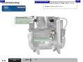
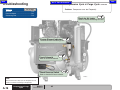
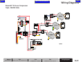
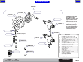
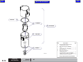
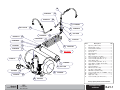
Troubleshooting
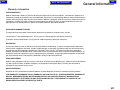
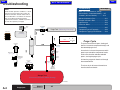
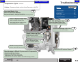
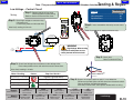
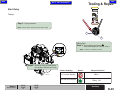
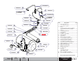
Compression Cycle
Atmospheric air is drawn in through intake filters to the compressor head(s) where air is
compressed and exhausted. Air travels through the pre-cooler where it is cooled 10 to 15 ° F (-12.2 to -9.4
Celsius) within ambient room temperature. Cool air enters the coalescent filter, which removes 99.9997% of all
particulate matter.
As the clean air travels through the desiccant tank it is dried to -25°F (-31.7 Celsius) dew point.
The clean dry air flows into the main storage tank through a check valve. Some air is directed to the purge
tank. As both tanks fill, the pressure switch opens at preset pressure and stops the
compressor.
Intake
Air
Intake
Filter
Purge Tank (Pressurizing)
PreCooler
Compressor
(Running)
White
Red
Atmospheric
Air
Pressurized
Air
Go To Page
Page:
Troubleshooting
Compressor will not Start ...................... A-6
Motor runs Intermittently or "Chugs"
ClassicSeries® (Lubricated Models)... A-7
PowerAir® (Oil-Less Models)...............A-8
Compressor Heads run but will not
Pressurize to 100 PSI .......................... A-9
Cycles with no Air in use ....................... A-10
Moisture Indicator is Pink ..................... A-11
Element Indicator is Red ....................... A-12
High Pressure ....................................... A-13
Excessive Noise ................................... A-14
Overheating .......................................... A-15
Compressor runs to Frequently ............. A-16
Excessive Oil Use (Lubricated Only) ..... A-17
Compressor Tripping Circut Breaker ...... A-18
Coalescing
Filter
Dessicant
Tank
Check Valve
(Open)
Storage
Air
Bottom Port
(Closed)
Normally Open
Solenoid Valve
(Closed)
EQUIPMENT ALERT
Room temperature should be between 40° and 100°F (4°C
to 38°C). Lack of proper ventilation is the main reason for
premature compressors failures. Whenever possible, use
exhaust fan to bring cool air from dental office to the
equipment room, or run fresh air intake lines to the outside
so the compressor can breathe in fresh, outside air.
Exhaust the stale, hot air out through the roof or side wall.
Moisture
Indicator
Pressure
Switch
(Contacts Closed)
Ball Valve
(Open)
100 PSI
Supply Air
to Operatory
Drain
Storage Tank
(Pressurizing)
AA184700
A-2
Models:
Compression Cycle
© Midmark Corporation 2007 SF-1899
Serial Numbers:
Rev 7/23/08
All
Back
Next
Go To Table Of Contents
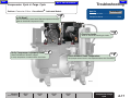
Troubleshooting
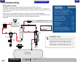
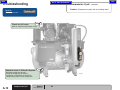
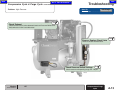
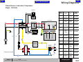
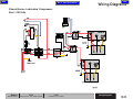
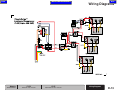
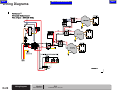
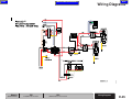
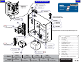
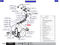
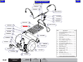
Compression Cycle
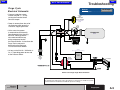
Electrical Schematic
Go To Page:
Refer to:
Page
Wire Diagrams ...................................... D-1
•Supply Line Voltage is always present on
one side of the Contactor contacts.
Solenoid
Valve
(Normally Open
when not energized)
• Line Voltage is also being supplied to the
240 / 24 VAC transformer energizing it.
ENERGIZED
(CLOSED)
•The Transformer supplies 24 VAC to the
On/Off switch on the wall and to one side
of the 24 VAC Contactor Coil.
When the On/Off switch is turned to the on
position and the Pressure Switch is closed,
the Contactor Coil is energized closing the
contacts.
Unit
On / Off
Switch
ON
LINE
VAC
Contactor
w/ 24 VAC Coil
CLOSED
24
VAC
Compressor
RUNNING
•With the contacts closed, line voltage is
supplied to one side on the Vac Unit On/Off
switch.
•When the Vac Unit On/Off switch is turned on,
line voltage is supplied to the motor.
CLOSED
(Below Pressure Setting)
•If the Pressure Switch is at 80 PSI
(+ / - 5 PSI) or below it's contacts are closed.
Power Source
•If the Contactor is closed, Line voltage is
then supplied to the Compressor energizing
it and the normally open Solenoid Valve,
closing the valve. This prevents the compressed
air from being discharged.
Pressure
Switch
Fuse
Wall
On / Off
Switch
ON
24 VAC
Transformer
ENERGIZED
LINE
VAC
Low Voltage
24
VAC
The system will continue to run until the pressure
inside the system reaches 100 PSI ( + / - 5 PSI).
Eariler Low Voltage Single Head Unit Shown
Models:
Serial Numbers:
All
Compression Cycle
© Midmark Corporation 2007 SF-1899
A-3
Rev 3/09
Back
Next
Go To Table Of Contents
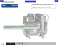
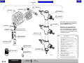
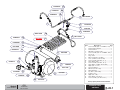
Troubleshooting
Go ToPage
Page:
Troubleshooting
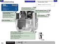
Motor runs Intermittently or "Chugs"
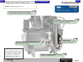
Note:
Under normal operation conditions, a small
amount of moisture with some oil may be
under the unloader exhaust muffler. This is
not a malfunction. It is evidence of what the
filter on the Desiccant Drying System
captured the moisture, and did not permit it
to enter the operatory air supply.
Check Valve
(Open)
Intake
Air
Intake
Filter
Purge Tank (Releasing Pressure)
PreCooler
ClassicSeries® (Lubricated Models).... .A-7
PowerAir®(Oil-Less Models)................A-8
Moisture Indicator is Pink ..................... A-11
Element Indicator is Red ....................... A-12
High Pressure ....................................... A-13
Excessive Noise ................................... A-14
Overheating .......................................... A-15
Compressor runs to Frequently ............. A-16
Compressor Tripping Circut Breaker ...... A-18
Compressor
(Not Running)
White
Red
Check Valve
(Closed)
Normally Open
Solenoid Valve
(Open)
Moisture
Indicator
Pressure
Switch
(Contacts Open)
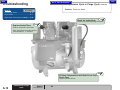
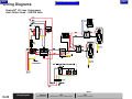
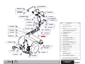
Air from the purge tank flows back through
the metered orifice.
Ball Valve
(Open)
The clean dry air drives out the moisture
from the desiccant beads.
100 PSI
Supply Air
to Operatory
Drain
Storage Tank
(Pressure at Pressure Switch Setting)
AA184800
A-4
Purge Cycle
© Midmark Corporation 2007 SF-1899
Models:
Serial Numbers:
All
Purge Cycle
A mechanical valve on the pressure switch
opens up to unload the compressor heads.
At the same time the unloader solenoid
opens, starting the purge cycle.
Storage
Air
Bottom Port
(Open)
Pressurized
Air
The pressure switch will open, shutting off
electrical current to compressor head(s) and
the solenoid/purge valve.
Coalescing
Filter
Dessicant
Tank
Atmospheric
Air
Back
Next
Go To Table Of Contents
Troubleshooting
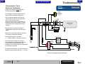
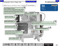
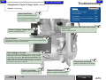
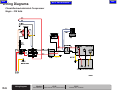
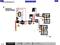
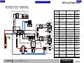
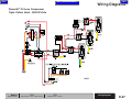
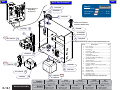
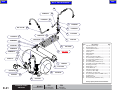
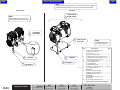
Purge Cycle
Electrical Schematic
Go To Page:
Refer to:
Page
Wire Diagrams ...................................... D-1
• Pressure inside the system
reaches 100 PSI (+ / - 5 PSI)
causing the Pressure Switch
Contacts to open.
Solenoid
Valve
(Normally Open
when not energized)
NOT ENERGIZED
(OPEN)
• Power is removed from the coil of
the Contactor which opens the
Contactor, stopping the motor.
Unit
On / Off
Switch
ON
• At the same time, power
is removed from the Normally
Open Solenoid Valve, Opening
the valve, allowing pressure
to be released from the top
of the compressor head to
the Exhaust Muffler. It also allows the
Purge Tank to release its
pressure thru the Desiccant
Tank to the Exhaust Muffler.
LINE
VAC
Contactor
w/ 24 VAC Coil
OPEN
24
VAC
Compressor
OFF
OPEN
(At or above Pressure Setting)
• As long as the Wall On / Off Switch is
On, it is providing power to one side
of the Pressure Switch.
Pressure
Switch
Fuse
Power Source
Wall
On / Off
Switch
ON
24 VAC
Transformer
ENERGIZED
LINE
VAC
Low Voltage
24
VAC
Eariler Low Voltage Single Head Unit Shown
Note:
The compression and purge cycles will continue as the pressure inside the system
fluctuates between the 80 PSI and 100 PSI pressure settings.
Models:
Serial Numbers:
All
Purge Cycle
© Midmark Corporation 2007 SF-1899 Rev 3/09
A-5
Back
Next
Go To Table Of Contents
Troubleshooting
Compression Cycle
Go To Page:
Refer To:
Page
Pressure Switch .................................... B-2
Problem: Compressor will not Start
ON/OFF Switch .................................... B-23
Capacitor .............................................. B-19
Thermal Overload Cut
Lubricated Models Only
Check Start Relay
Allow compressor to cool, then restart.
Compressor Heads ............................... B-29
Low Voltage .......................................... B-16
3rd
5th
Refer to: Section B Compressor Heads
(Motor may hum but not Start)
Tap capacitor box lightly. If unit starts,
relay is sticking and needs replaced.
Check Relay for continuity.
Refer to Section B - Start Relay
1st
Check Low Voltage
Check Capacitor
Refer to: Section B Capacitor
Refer to: Section B Low Voltage
2nd
Was proper voltage is measured at the breaker and not at motor terminals?
If yes, check the in the following order :
•Check for broken or loose wires.
•If there is Pressure, Perform Pressure Switch Adjustment.
(Refer to: B Pressure Switch)
•Check voltage at On/Off Switch.
(Refer to: B On/Off Switch)
Check voltage at Breaker
A-6
Compression Cycle
© Midmark Corporation 2007 SF-1899 Rev 3/09
6th
Motor/Compressor Frozen
Models:
Serial Numbers:
All
4th
Back
Next
Go To Table Of Contents
Troubleshooting
Compression Cycle & Purge Cycle
®
Problem: Motor runs Intermittently or "Chugs" - ClassicSeries
1st
Check Voltage in Breaker
Go To Page
Page:
Refer To:
Start Relay ............................................ B-27
Capacitor .............................................. B-19
Lubricated Models
Note: If circuit breaker is tripped, measure voltage at the line
side of the vacuum switch while the unit is running. Voltage
should be in the range of 208-230 (for 230 volt units) and
108-132 (for 120 volt units). Voltage outside this range may
result in failure to start and possible damage to unit. Install a
buck/boost transformer as required.
Solenoid ............................................... B-12
Check Valve ......................................... B-21
7th
Check Capacitor
Refer to: Section B Capacitor
Check Low Voltage
2nd
Refer to: Section B Low Voltage
3rd
Check On/Off Switch
6th
Refer to: Section B On/Off Switch
Check for Stuck Relay
If the start capacitor is warm to the touch, start relay is not releasing.
Replace the start relay.
4th
Check Pressure Switch
Refer to: Section B Pressure Switch
Check for Stuck Check Valve
5th
Check Ambient Room Temperature.
9th
Refer to: Section B Check Valve
Verify temperature of room is not subjected below 40°
Fahrenheit or hard starting may result.
Use Midmark Oil, pn 77000953 .
Check Exhaust Valve 8th
Refer to: Section B Solenoid
Models:
Serial Numbers:
CL21
All
CL22
All
AA187300
CL32
All
CL52
All
Compression & Purge
Cycle
© Midmark Corporation 2007 SF-1899
Rev 9/09
A-7
Back
Troubleshooting
Compression Cycle & Purge Cycle
Go To Page:
Problem: Motor runs Intermittently or "Chugs" - PowerAir
Refer To:
Page
Low Voltage ......................................... B-16
On/Off Switch ....................................... B-23
Pressure Switch .................................... B-2
1st
Note: If circuit breaker is tripped, measure voltage at the line
side of the vacuum switch while the unit is running. Voltage
should be in the range of 208-230 (for 230 volt units) and
108-132 (for 120 volt units). Voltage outside this range may
result in failure to start and possible damage to unit. Install a
buck/boost transformer as required.
2nd
®
- Oil Less Models
6th
Check for Blockage in Air Line
Check Voltage in Breaker
Check Low Voltage
Next
Go To Table Of Contents
Remove discharge hose from head and test run.
If unit runs correctly check for obstruction in air line to storage tank.
Obstruction will be at an orifice or other restriction.
Refer to: Section B Low Voltage
3rd
Check On/Off Switch
Refer to: Section B On/Off Switch
Check Pressure Switch
4th
Refer to: Section B Pressure Switch
5th
Purge System
Purge system by pulling open the pressure relief valve.
A-8
Compression & Purge
Cycle
© Midmark Corporation 2007 SF-1899 Rev 3/09
Models:
Serial Numbers:
P21
All
P22
All
P32
All
P52
All
P72
All
Back
Go To Table Of Contents
Compression Cycle
- continued
Problem: Compressor Heads run but will not Pressurize to 100 PSI
8th
Lubricated Models Only
Check for Pressure Build Up
Next
Troubleshooting
Go To Page:
Refer To:
Page
Solenoid ............................................... B-12
Pressure Switch .................................... B-2
Coalescing Filter ................................... B-11
Intake Filter ........................................... B-7
Checking for Leaks ............................... B-10
Remove discharge line, hold finger over fitting.
If low pressure build -up, head(s) are defective and need replaced.
Compressor Heads ............................... B-29
Clean or Replace Intake Filter
5th
Refer to: Section B Intake Filter.
P21, P22, P32 Models Only
Check for Worn Piston Cup
Note: Intake filters on earlier versions
are mounted on a "T" manifold.
9th
Refer to: Section B Compressor Heads
Check for Blockage in Air Line
6th
Inspect all air lines for restrictions.
Check Coalescing Filter 4th
If indicator is red, change filter.
Check for leaks or cracks.
Refer to: Section B Coalescing Filter
2nd
Check Exhaust Valve
Refer to: Section B Solenoid.
Check Pressure Switch
3rd
Refer to: Section B Pressure Switch.
1st
Check for leaks in Office Air System and in Compressor
7th
Verify Shut-Off valve is Closed.
•Close the storage tank shut off.
•Pump up storage tank to 100 PSI.
•If pressure is maintained at 100 PSI for
15-20 minutes, leak is not in compressor.
If pressure does not maintain, Refer to: Section B Checking for leaks.
Models:
Serial Numbers:
All
Compression & Purge
Cycle
© Midmark Corporation 2007 SF-1899
Rev 2/08
A-9
Back
Troubleshooting
Compression Cycle
2nd
Refer to: Section B Checking for Leaks.
Check for Leak in Office Air System
1st
Close the storage tank shut off.
•Pump up storage tank to 100 PSI.
•If pressure is maintained at 100 PSI for
15-20 minutes, leak is not in compressor.
A-10
Compression Cycle
© Midmark Corporation 2007 SF-1899
- continued
Problem: Compressor cycles with no air being used
Go To Page:
Refer To:
Page
Checking for Leaks ............................... B-10
Check for Air Leaks
Next
Go To Table Of Contents
AA187500
Models:
Serial Numbers:
All
Back
Next
Go To Table Of Contents
Troubleshooting
Compression Cycle & Purge Cycle- continued
Problem: Moisture Indicator is Pink
Is Compressor running too frequently?
Refer to: Section A Compressor runs to Frequently.
Go To Page:
Refer To:
Page
Desiccant Tank ..................................... B-15
3rd
Solenoid ............................................... B-12
Compressor runs to frequently .............. A-16
2nd
Check Desiccant Drying Chamber
Refer to: Section B Desiccant Tank
Perform Unloading System Function Test
1st
Purge System
5th
Purge system by pulling open
the pressure relief valve.
Refer to: Section B - Solenoid
Note:
Under normal operation conditions, a small
amount of moisture with some oil may be
under the unloader exhaust muffler. This is
not a malfunction. It is evidence that the
filter on the Desiccant Drying System
captured the moisture, and did not permit it
to enter the operatory air supply.
Models:
Serial Numbers:
All
AA187600
Check for Condensation in Air Lines
Is there moisture in operatory air?
4th
Compression & Purge
Cycle
© Midmark Corporation 2007 SF-1899
A-11
Back
Next
Go To Table Of Contents
Troubleshooting
Compression Cycle & Purge Cycle- continued
Problem: Element Indicator is Red
Go To Page:
Refer To:
Page
Intake Filter ........................................... B-7
Coalescing Filter ................................... B-11
Change Intake Filter
1st
Refer to: Section B Intake Filter.
Note: Intake filters on earlier versions
are mounted on a "T" manifold.
Change Coalescing Filter
2nd
Refer to: Section B Coalescing Filter
A-12
Compression & Purge
Cycle
© Midmark Corporation 2007 SF-1899
Rev 2/08
Models:
Serial Numbers:
All
Back
Next
Go To Table Of Contents
Troubleshooting
Compression Cycle & Purge Cycle- continued
Problem: High Pressure
Refer To:
Page
Go To Page:
Check Valves ....................................... B-21
1st
Check Exhaust
Remove hoses one at a time between Heads and Pressure Relief Valve.
Verify exhaust air flow is not obstructed.
2nd
Clean or Replace Check Valve
Refer to: Section B Check Valve
3rd
Check Pressure Switch Settings
Check contacts and operating range, 80 - 100 psi.
AA187800
Models:
Serial Numbers:
All
Compression & Purge
Cycle
© Midmark Corporation 2007 SF-1899
A-13
Back
Next
Go To Table Of Contents
Troubleshooting
Compression Cycle & Purge Cycle- continued
Problem: Excessive Noise
Go To Page:
Refer To:
Page
Checking for Leaks ............................... B-10
Intake Filters ......................................... B-7
Quiet Cover / Fans (Oil Less Models) ... B-38
1st
Check for Leaky Hose
Refer to: Section B Checking for Leaks
Replace Intake Filters
2nd
Refer to: Section B Intake Filters.
Note: Intake filters on earlier versions
are mounted on a "T" manifold.
3rd
Oil-Less Compressors with Quiet Cover Only
Check Fans
Refer to: Section B Fans
A-14
Compression & Purge
Cycle
© Midmark Corporation 2007 SF-1899
Rev 2/08
Models:
Serial Numbers:
All
Back
Next
Go To Table Of Contents
Troubleshooting
Compression Cycle & Purge Cycle- continued
Go To Page:
Refer To:
Page
Intake Filter ........................................... B-7
Solenoid (Exhaust Valve) ...................... B-12
Problem: Overheating
1st
Clean Intake Filters
Refer to: Section B Intake Filters.
Pressure Switch .................................... B-2
Low Voltage .......................................... B-16
Note: Intake filters on earlier versions
are mounted on a "T" manifold.
Quiet Cover / Fans (Oil Less Models) ... B-38
On/Off Switch ....................................... B-23
8th
2nd
Clean or Replace Exhaust Valve
Oil-Less Compressors with Quiet Cover Only
Check Fans
Refer to: Section B Fans
Refer to: Section B Solenoid.
3rd
Check Exhaust
Remove hoses one at a time between Heads and Pressure Relief Valve.
Verify exhaust air flow is not obstructed.
4th
Check Voltage in Breaker
Note: If circuit breaker is tripped, measure voltage at the line
side of the vacuum switch while the unit is running. Voltage
should be in the range of 208-230 (for 230 volt units) and
108-132 (for 120 volt units). Voltage outside this range may
result in failure to start and possible damage to unit. Install a
buck/boost transformer as required.
Check Pressure Switch
7th
Refer to: Section B Pressure Switch
Check Low Voltage
5th
Refer to: Section B Low Voltage
Models:
Serial Numbers:
All
6th
Check On/Off Switch
Refer to: Section B On/Off Switch
Compression & Purge
Cycle
© Midmark Corporation 2007 SF-1899
Rev 3/09
A-15
Back
Next
Go To Table Of Contents
Troubleshooting
Compression Cycle & Purge Cycle- continued
Go To Page:
Refer To:
Page
Solenoid ............................................... B-12
Problem: Compressor runs too Frequently
Pressure Switch .................................... B-2
Coalescing Filter ................................... B-11
1st
Check for Air Leaks
Refer to: Section B Checking for Leaks
Change Element Indicator 2nd
Refer to: Section B Coalescing Filter
3rd
Check Solenoid
Refer to: Section B Solenoid
Check Pressure Switch
4th
Refer to: Section B Pressure Switch
AA188100
Note:
More than the 35% duty cycle for Compressors are
rated for would be "Running too Frequently".
A-16
Compression & Purge
Cycle
© Midmark Corporation 2007 SF-1899
Models:
Serial Numbers:
All
Back
Next
Go To Table Of Contents
Troubleshooting
Compression Cycle & Purge Cycle
®
Problem: Excessive Oil Use - ClassicSeries
Lubricated Models
1st
Is Oil Black?
Go To Page:
Refer To:
Page
Checking for Leaks ............................... B-10
Compressor Heads ............................... B-29
Black oil indicates a worn head. Replace compressor head(s).
Refer to: Section B Compressor Heads
3rd
Check for Leaks
Refer to: Section B Checking for Leaks.
Verify Compressor is properly sized.
2nd
4th
Check with Midmark Technical support
to verity compressor is undersized for installation.
Check Ambient Room Temperature.
Verify temperature of room is not subjected above 100° Fahrenheit.
AA188200
Models:
Serial Numbers:
CL21
All
CL22
All
CL32
All
CL52
All
Compression & Purge
Cycle
© Midmark Corporation 2007 SF-1899
A-17
Back
Next
Go To Table Of Contents
Troubleshooting
Go To Page:
Refer To:
Page
Purge Valve .......................................... B-34
Compression Cycle & Purge Cycle- continued
Problem: Compressor Trips off the Circuit Breaker
Do you hear air excaping from the solenoid valve after the compressor shuts off? 1st
If yes, check Solenoid.
If no, check purge valve for obstruction. Refer to: Purge Valve
AA194600
A-18
Compression & Purge
Cycle
© Midmark Corporation 2007 SF-1899
Models:
Serial Numbers:
All
Back
Next
Go To Table Of Contents
Section B
Testing & Repair
Go To Page:
Components
Page
Pressure Switch .................................... B-2
Intake Filter .......................................... B-8
Checking for Leaks ............................. B-11
Coalescing Filter .................................. B-12
Solenoid ............................................... B-13
Desiccant Tank .................................... B-16
Low Voltage Control Circuit & Contactor
..........................................................B-18
Capacitor .............................................. B-20
Check Valve ......................................... B-22
ON/OFF Switches ................................ B-24
Fuse
............................................... B-26
Start Relay (Lubricated Models Only) .. B-28
Compressor Heads (Listed by Model)
CL21, CL22, CL32 and CL52 .............. B-30
P21, P22 and P32 ............................... B-32
P52 and P72 ......................................... B-33
Purge Valve .......................................... B-35
Thermal Overload Switch ..................... B-37
Fan (Oil Less Models with Quiet Cover)
..........................................................B-39
Click GO TO PAGE: button (then enter desired page
number) to view any page in this document.
© Midmark Corporation 2007 SF-1899
B-1
Back
Testing & Repair
Pressure Switch
Go To Page:
Refer to:
Page
Testing ............................................... B-3
Location and Function
Adjustment ........................................... B-5
Wiring Diagrams .................................... D-1
During the Compression Cycle...
When the storage tank is filled to the preset pressure
the pressure switch will open and stop the compressor.
Exploded views ..................................... E-1
During the Purge Cycle...
The pressure switch shuts off current to the compressor
head(s) and the solenoid / purge valve.
A mechanical valve on the pressure switch opens up to
unload the compressor headlines. At the same time the
solenoid opens, starting the purge cycle.
Cut-In / Cut-Out time
Cut-In / Cut-Out is the minimum and maximum
discharge pressures at which the compressor will
switch from unload to load operation (cut-in) or from
load to unload (cut-out). The pressure switch
controls Cut-In / Cut-Out times.
B-2
Pressure Switch
© Midmark Corporation 2007 SF-1899
Next
Go To Table Of Contents
Models:
Serial Numbers:
All
Back
Next
Go To Table Of Contents
Pressure Switch -
Testing & Repair
continued
Go To Page:
Refer to:
Page
Adjustment ........................................... B-5
Access Procedures ............................... C-1
Testing - *Note - This procedure is only for units with Serial Numbers listed below.
Refer to following pages for other Serial Number listings.
Step 1: Perform Adjustment.
Refer to Section B Pressure Switch Adjustment.
Step 2: Turn power off.
Step 3: Remove pressure switch cover and verify there are no black/burnt melted wires.
If there are replace pressure switch.
Refer to Section C Pressure Switch Cover
YEL
YEL
Step 4: Turn power on.
L1
T1
Caution
When testing components
with power on use care to
prevent electrical shock.
Step 5: Set meter to V.
Step 6: Place meter probes on
both yellow wires.
Meter Reading
Status
Less than 24 Volts on Reading
Replace Pressure Switch.
Pressure Switch - OK
24 Volt Reading
Serial Numbers:
Models:
Serial Numbers:
Test Pressure Switch during purge cycle.
During compression cycle Pressure Switch is closed
and has no voltage.
AA185100
No Pressure on Gauge
Models:
Attention:
Required Action
CL21
CL22
CL32
CL52
0701L210001
thru 0901L210370
0701L220001
thru 0903L220294
0701L320001
thru 0901L320807
0701L520001
thru 0810CL520124
P32
P52
P72
0703P210001
thru 0902P520467
0703P210001
thru 0903P720190
P21
0703P210001
thru 0903P210361
P22
0703P220001
thru 0903P221139
0703P210001
thru 0903P321137
Pressure Switch
© Midmark Corporation 2007 SF-1899
B-3
Rev 8/09
Back
Testing & Repair
Pressure Switch -
Next
Go To Table Of Contents
continued
Go To Page:
Refer To:
Page
Function and Location ........................... B-2
Adjustment ........................................... B-6
Testing *Note - This procedure is only for units with Serial Numbers listed below.
Step 1: Perform Adjustment.
Refer to Section B Vacuum Switch Adjustment.
Access Procedures ............................... C-1
Wire Diagrams ...................................... D-1
Step 2: Turn power off.
Exploded Views .................................... E-1
Step 3: Remove vacuum switch cover and verify there are no black/burnt melted wires.
If there are replace pressure switch.
Refer to Section C Vacuum Switch Cover
Step 4: Turn power on.
WARNING
High Voltage. When testing
components with power on use
care to prevent electrical shock.
T2
L2
Step 5: Set meter to V.
T1
L2
L1
T2
L1
T1
Step 6: • Bleed tank pressure down to less than 80 PSI.
Meter Reading
Status
Required Action
AA185101
Voltage Not Equal
Replace Pressure Switch.
T1 & T2 Voltage
=
L1 & L2 Voltage
Pressure Switch - OK
Models:
Serial Numbers:
B-4
Models:
Pressure Switch
© Midmark Corporation 2007 SF-1899
Serial Numbers:
Rev 10/09
• Pressure switch will make an audible click.
• Check line voltage across L1 and L2.
• Check line voltage across T1 and T2.
• These voltages should be the same.
CL21
CL22
CL32
CL52
All
0902L210372
thru Present
0903L220296
thru Present
0901L320813
thru Present
0810L520126
thru Present
V785000
thru Present
P21
0904P210365
thru Present
P22
0904P221146
thru Present
P32
0904P321145
thru Present
P52
P72
0904P520474
thru Present
0903P720191
thru Present
Back
Next
Go To Table Of Contents
Pressure Switch -
Testing & Repair
continued
Adjustment - *Note - This procedure is only for units with Serial Numbers listed below.
Refer to following pages for other Serial Number listings.
Go To Page:
Refer To:
Page
Function and Location ........................... B-2
Testing ............................................... B-3
Access Procedures ............................... C-1
Wire Diagrams ...................................... D-1
Cut-In Adjustment
Exploded Views .................................... E-1
Step 1: Run compressor until pressure reaches 100 lbs.
Note:
Compressor should shut off close to 100 lbs.
L1
Cut-In Adjuster
T1
T2
L2
AA185200
Step 2: If compressor didn't shut down
at 100 lbs, turn nut on adjuster
to reset gauge.
•Clockwise will increase reading.
•Counter Clockwise will decrease reading.
Models:
Serial Numbers:
Models:
Serial Numbers:
CL21
CL22
CL32
CL52
0701L210001
thru 0901L210370
0701L220001
thru 0903L220294
0701L320001
thru 0901L320807
0701L520001
thru 0810CL520124
P32
P52
P72
0703P210001
thru 0902P520467
0703P210001
thru 0903P720190
P21
0703P210001
thru 0903P210361
P22
0703P220001
thru 0903P221139
0703P210001
thru 0903P321137
Pressure Switch
© Midmark Corporation 2007 SF-1899
Rev 8/09
B-5
Back
Testing & Repair
Pressure Switch -
Next
Go To Table Of Contents
continued
Go To Page:
Refer To:
Page
Function and Location ........................... B-2
Testing ............................................... B-4
Adjustment - *Note - This procedure is only for units with Serial Numbers listed below.
Refer to following pages for other Serial Number listings.
Access Procedures ............................... C-1
Wire Diagrams ...................................... D-1
Cut-In Adjustment
Exploded Views .................................... E-1
Step 1: Run compressor until pressure reaches 100 lbs.
Note:
Compressor should shut off close to 100 lbs.
Cut-In Adjuster
AA185201
Step 2: If compressor didn't shut down
at 100 lbs, turn nut on adjuster
to reset gauge.
•Clockwise will increase reading.
•Counter Clockwise will decrease reading.
Models:
Serial Numbers:
B-6
Pressure Switch
© Midmark Corporation 2007 SF-1899
Models:
Serial Numbers:
Rev 10/09
CL21
CL22
CL32
CL52
All
0902L210372
thru Present
0903L220296
thru Present
0901L320813
thru Present
0810L520126
thru Present
V785000
thru Present
P21
0904P210365
thru Present
P22
0904P221146
thru Present
P32
0904P321145
thru Present
P52
0904P520474
thru Present
Back
Next
Go To Table Of Contents
Testing & Repair
Go To Page:
Refer To:
Page
Function and Location .......................... B-2
Testing ............................................... B-4
Access Procedures ............................... C-1
Wire Diagrams ...................................... D-1
Exploded Views .................................... E-1
Cut-In Adjustment
Step 1: Run compressor until pressure reaches 100 lbs.
Note:
Compressor should shut off close to 100 lbs.
Cut-Out Adjustment
Step 1: Run compressor until pressure reaches 100 lbs.
Note:
Cut-Out Adjuster
Cut-In Adjuster
Step 2: If compressor didn't shut down
Step 2: Compressor should start back up after a 20 lb
at 100 lbs, turn nut on adjuster
to reset gauge.
drop on the gauge. If needed, turn nut to adjust.
•Clockwise will increase reading.
•Counter Clockwise will decrease reading.
NOTE:
Models:
Serial Numbers:
P72
0903P720191
thru Present
Compressor should shut off close to 100 lbs.
If not perform a Cut-In adjustment
P72
V785000
thru Present
•Clockwise will increase reading.
•Counter Clockwise will decrease reading.
Pressure Switches on models up to 2 HP have a Preset Cut-In adjuster.
Models 2HP and over have Manual adjuster for Cut-In setting.
Both Models have Manual Cut-Out Adjusters.
P72 Pressure Switch
© Midmark Corporation 2007 SF-1899
B-7
Rev 3/28/14
Back
Next
Go To Table Of Contents
Testing & Repair
Intake Filters
Go To Page:
Intake Filters
Page
Clean (Rock and Lubricated Heads) ..... B-9
Clean (Cattani Heads) .......................... B-10
Function and Location
Atmospheric air is drawn in through
intake filters before flowing to the
compressor heads.Intake filter
protect the heads from dust and debris
and should be changed annually.
Exploded Views .................................... E-1
Filters
Filters
Filters
Earlier
Versions
AA192900
Newer
Versions
B-8
Models:
Intake Filter
© Midmark Corporation 2007 SF-1899
Serial Numbers:
Rev 2/08
All
Back
Next
Go To Table Of Contents
Testing & Repair
Intake Filter
Clean
Step 1: Remove exhaust hose from filter housing.
Unscrew intake filter from intake manifold
assembly or compressor head.
Step 3: Remove filter and clean with a nonflammable solvent.
Wipe out housing and allow filter and housing to dry.
Step 5: Screw onto intake manifold assembly.
Install exhaust hose onto filter housing.
Do Not Remove Cap
Pop End of Housing off to Access Filter
Step 2: Pop off one side of filter housing.
Step 4: Install filter back into housing.
Assemble housing.
Models:
Serial Numbers:
CL21
CL22
CL32
CL52
P21
P22
P32
All
All
All
All
Intake Filter
(Thomas and
Lubricated Heads)
© Midmark Corporation 2007 SF-1899
Rev 2/08
B-9
Back
Next
Go To Table Of Contents
Testing & Repair
Intake Filter
Clean
Step 1: Firmly grab black boot, twist, rock and pull outward.
Step 4: Push boot flange evenly onto filter.
Step 5: Reinstall boot in compressors head and firmly
press around boot flange to secure in place.
Step 2: Remove filter from boot.
Step 3: Blow off dust and dirt with a compressor.
Intake Filter
B-10
(Cattani Heads)
© Midmark Corporation 2007 SF-1899
Models:
Serial Numbers:
P52
P72
All
All
Back
Next
Go To Table Of Contents
Testing & Repair
Checking for Leaks
Caution
Check
Step 2: Turn power on.
Avoid water contact with electrical parts.
Note: Compressor should run quietly and
storage tank will begin to pressurize.
Step 3: Use soapy water to check for compressor
plumbing joint leaks.
Soapy
Water
Check
Step 1: Verify shut-off valve is closed.
Check Valve in Closed Position
AA190100
Models:
Serial Numbers:
All
Checking for Leaks
© Midmark Corporation 2007 SF-1899
B-11
Back
Go To Table Of Contents
Testing & Repair
Coalescing Filter
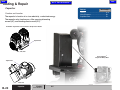
Function and Location
The Coalescing Filter removes water, oil and other contaminates from compressed air.
Coalesced liquids gravitate into the sump bowl where they are discharged through the drain.
On the ClassicSeries® Lubricated models, the filter needs replaced biannually, or every 350
hrs, based on 2000 hour work year times 35 percent duty cycle.
On the PowerAir® Oil-Less models, the filter needs replaced annually, or every 700 hrs, based
on 2000 hour work year times 35 percent duty cycle.
B-12
Coalescing Filter
© Midmark Corporation 2007 SF-1899
Models:
Serial Numbers:
All
Next
Back
Go To Table Of Contents
Solenoid
Next
Testing & Repair
Go To Page:
Refer to:
Page
Testing ............................................... B-14
Function and Location
During the compression cycle...
The normally open Solenoid Valve, closes, preventing
the compressed air from being discharged to the drain.
Wiring Diagrams .................................... D-1
Exploded views ..................................... E-1
During the purge cycle...
Power is removed from the Normally Open Solenoid Valve,
Opening the valve, allowing pressure to be released from the top
of the compressor head to the drain.
It also allows the Purge Tank to release its pressure thru the
Desiccant Tank to the drain, regenerating the desiccant drying
system.
Models:
Serial Numbers:
All
Solenoid
© Midmark Corporation 2007 SF-1899
B-13
Back
Next
Go To Table Of Contents
Testing & Repair
Solenoid
Go To Page:
Refer to:
Page
Access Procedures ............................... C-1
Testing - *Note - This procedure is only for units with Serial
Numbers listed below. Refer to following pages for other Serial
Number listings.
Wiring Diagrams .................................... D-1
Exploded views ..................................... E-1
Step 1: Remove electrical box cover.
Refer to Section C Electrical Box Cover
Step 2: Set meter to V.
Step 3: Place meter probes on
contactor solenoid
wire connections.
Caution
When testing components
with power on use care to
prevent electrical shock.
Step 4: Clean solenoid.
Meter Reading
Status
• Loosen nut on top of
solenoid and lift top off.
• Wipe stem off with a clean
rag.
• Using a spanner wrench to
remove stem from
valve body. (If spanner
wrench not available
use standard wrench very
carefully)
• Clean internal valve
plunger, ports and seat.
• Reassemble.
Required Action
Less than 230 Volts on 230 Volt units.
Less than 115 Volts on 115 Volt units.
Replace Solenoid
Doesn't work after cleaning.
230 Volt Reading on 230 Volt units.
Solenoid - OK
115 Volt Reading on 115 Volt units.
Works after Cleaning.
Models:
Serial Numbers:
B-14
Models:
Solenoid
© Midmark Corporation 2007 SF-1899
Serial Numbers:
Rev 8/09
AA190600
CL21
CL22
CL32
CL52
0701L210001
thru 0901L210370
0701L220001
thru 0903L220294
0701L320001
thru 0901L320807
0701L520001
thru 0810CL520124
P21
0703P210001
thru 0903P210361
P22
0703P220001
thru 0903P221139
P32
0703P210001
thru 0903P321137
P52
P72
0703P210001
thru 0902P520467
0703P210001
thru 0903P720190
Back
Next
Go To Table Of Contents
Testing & Repair
Solenoid
Testing - *Note - This procedure is only for units with Serial Numbers listed below.
Go To Page:
Refer to:
Page
Access Procedures ............................... C-1
Wiring Diagrams .................................... D-1
Exploded views ..................................... E-1
Step 2: Set meter to V.
Step 1: Remove electrical box cover.
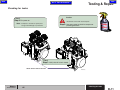
Refer to Section C Electrical Box Cover
Step 3: • Check if line voltage is present
at solenoid wires (115 or 230 VAC).
• If you have voltage, then
shut power off and clean solenoid.
• If solenoid still doesnt work
after cleaning, replace.
To Clean Solenoid...
A.) Loosen nut on top of solenoid and lift top off.
B.) Wipe stem off with a clean rag.
C.) Using a spanner wrench to remove stem from valve body.
(If spanner wrench not available use standard wrench very carefully)
D.) Clean internal valve plunger, ports and seat.
E.) Reassemble.
Models:
Serial Numbers:
Models:
Serial Numbers:
CL21
CL22
CL32
CL52
0902L210372
thru Present
0903L220296
thru Present
0901L320813
thru Present
0810L520126
thru Present
P21
0904P210365
thru Present
P22
0904P221146
thru Present
P32
0904P321145
thru Present
AA190600
All
V785000
thru Present
P52
P72
0904P520474
thru Present
0903P720191
thru Present
Solenoid
© Midmark Corporation 2007 SF-1899
Rev 10/09
B-15
Back
Go To Table Of Contents
Testing & Repair
Desiccant Tank
Function and Location
Moisture vapor drying takes place as the air is directed through the silica and
alumina gel (desiccant material) from bottom to top in the drying chamber of the
desiccant tank.
When the desiccant becomes so saturated with water and oil that the purge cycle
fails to regenerate it, the desiccant tank will need to be replaced.
Models:
Desiccant Tank
B-16
Serial Numbers:
© Midmark Corporation 2007 SF-1899
Rev 9/07
All
Next
Back
Go To Table Of Contents
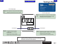
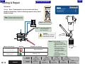
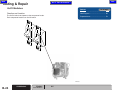
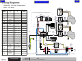
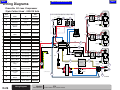
Low Voltage - Master Control Panel
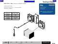
Function and Location
The Master Control Panel will allow the user to control
the dental equipment from the office area.
Supplies power to the relay switch.
Next
Testing & Repair
Go ToPage
Page:
Low Voltage Control
Testing ............................................... B-18
Wiring Diagrams .................................... D-1
Exploded Views .................................... E-1
*Note: Relay Switch is always live unless Low Voltage is turned off.
Air
Va
c
Wa
ter
AA195600
Models:
Serial Numbers:
All
Low Voltage Contactor
© Midmark Corporation 2007 SF-1899
B-17
Back
Next
Go To Table Of Contents
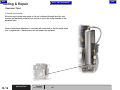
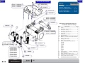
Testing & Repair
Go To Page:
Low Voltage
Page
Fuse
............................................... B-26
Access Procedures ............................... C-1
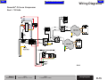
Low Voltage - Control Circuit
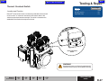
Step 1: Remove electrical box cover.
Testing
Check for broken or loose wiring.
Refer to: Section C Electrical Box Cover
Relay
Wiring Diagrams .................................... D-1
Exploded Views .................................... E-1
Step 2: Check high voltage on contactor relay.
• Set meter to V.
• Place meter probes on front, black and white wires.
Step 4: Insert screwdriver into relay to start manually.
Note: Verify reading is 230 volts.
Note: if system starts, replace contactor relay.
230 VAC Primary
Transformer
Relay
230 VAC Secondary
WHT
Caution
When testing components
with power on use care to
prevent electrical shock.
YLW
RED
LOW
VOLTAGE
CONTROL
BLU
WHITE
BLUE
BLU
Step 5: Check fuse. Visually check to see if blown.
1/2 A
FUSE
Refer To: Section B Fuse
Step 3: Check Low Voltage from transformer to low voltage wires.
Place meter probes on Yellow and Red wire contactor connections.
Note: Verify reading is 24 volts.
Meter Reading
Status
Required Action
Low Voltage = < 24 Volts
Contactor Relay - OK
Transformer - OK
High Voltage = Line Voltage
Low Voltage = 24 Volts
Models:
Serial Numbers:
Models:
Low Voltage
© Midmark Corporation 2007 SF-1899
it is not defective.
Disconnect the Red, White and Blue
wires from the remote switch.
Connect the Blue and Red wires
together.
Replace Contactor Relay
Replace Transformer
High Voltage = < Line Voltage
B-18
Step 6: Bypass the remote switch to verify
Serial Numbers:
Rev 8/09
AA158701i
CL21
CL22
CL32
CL52
0701L210001
thru 0901L210370
0701L220001
thru 0903L220294
0701L320001
thru 0901L320807
0701L520001
thru 0810CL520124
P21
0703P210001
thru 0903P210361
P22
0703P220001
thru 0903P221139
P32
0703P210001
thru 0903P321137
P52
P72
0703P210001
thru 0902P520467
0703P210001
thru 0903P720190
Back
Next
Go To Table Of Contents
Testing & Repair
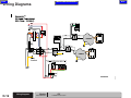
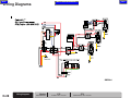
*Note - This procedure is only for units with Serial Numbers listed below.
Low Voltage - Control Circuit
Go To Page
Page:
Refer To:
Fuse ..................................................B-26
Wiring Diagrams .................................... D-1
Step 1: Remove electrical box cover.
Check for broken or loose wiring.
Refer to: Section C Electrical Box Cover
Testing
Exploded Views .................................... E-1
Relay
Step 2: Check high voltage on contactor relay.
• Set meter to V.
• Place meter probes on indicated wires.
Step 4: Insert screwdriver into relay to start manually.
Note: Verify reading is 230 volts.
Note: If system starts, replace contactor relay.
BLU
230 VAC
Transformer
Relay
24 VAC
YEL
WARNING
RED
WHT
LOW
VOLTAGE
CONTROL
High Voltage. When testing
components with power on use
care to prevent electrical shock.
RED
BLUE
Step 5: Check fuse.
Refer To: Section B Fuse
Step 3: Check Low Voltage from transformer to low voltage wires.
Place meter probes on blue and red wire contactor connections.
Note: Verify reading is 24 volts.
Meter Reading
Status
Required Action
Replace Contactor Relay
Replace Transformer
High Voltage = < Line Voltage
Low Voltage = < 24 Volts
Low Voltage = 24 Volts
Serial Numbers:
Models:
Serial Numbers:
Step 6: Bypass the remote switch to verify it is not defective.
Disconnect the Red, White and Blue wires from the remote switch.
Connect the Blue and Red wires together.
If the relay and fans work, then replace remote switch or wiring.
Contactor Relay - OK
Transformer - OK
High Voltage = Line Voltage
Models:
AA158702i
CL21
CL22
CL32
CL52
0902L210372
thru Present
0903L220296
thru Present
0901L320813
thru Present
0810L520126
thru Present
P21
0904P210365
thru Present
P22
0904P221146
thru Present
P32
0904P321145
thru Present
P52
0904P520474
thru Present
All
V785000
thru Present
P72
0903P720191
thru Present
Low Voltage
© Midmark Corporation 2007 SF-1899
Rev 10/09
B-19
Back
Next
Go To Table Of Contents
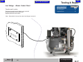
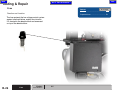
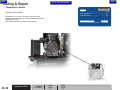
Testing & Repair
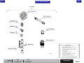
Capacitor
Go To Page:
Refer to:
Page
Testing ...............................................B-21
Wiring Diagrams .................................... D-1
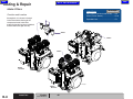
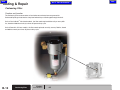
Function and Location
The capacitor’s function is to store electricity, or electrical energy.
The capacitor also functions as a filter, passing alternating
current (AC), and blocking direct current (DC).
Exploded views ..................................... E-1
PowerAir® Capacitors are located on Compressor Heads
Capacitors
P21, P22, P32
ClassicSeries®
Capacitor-Relay Box
Capacitors
AA92800
P52, P72
B-20
Capacitor
© Midmark Corporation 2007 SF-1899
Models:
Serial Numbers:
All
Back
Next
Go To Table Of Contents
Testing & Repair
Capacitor
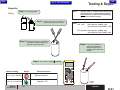
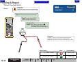
Testing
NOTE:
Step 1: Disconnect power.
The best check is to replace the capacitor with
a known good one. The replacement capacitor
MUST be of the same Mfd and Voltage Ratings
or the motor could be damaged.
Step 2: Access start and run capacitors
and disconnect capacitor wiring.
NOTE:
1HP 115V
Run Capacitor: 40MFD 370v
Start Capacitor: 430-516MFD 125v
1HP 208-230v Run Capacitor: 20MFD 440v
Start Capacitor: 145-174MFD 220v
Step 3: Discharge capacitors by touching
screwdrivers to two contacts on a
capacitor and to each other.
Step 5: Place meter probes on
capacitor connectors.
Reverse the leads, this
should produce the same
reading.
Step 4: Set meter to highest Ω reading.
Meter Reading
Status
"O" or "Open" Reading
Replace Capacitor
Start Low and Increases
Models:
Serial Numbers:
Required Action
Capacitor - OK
All
Capacitor
© Midmark Corporation 2007 SF-1899
Rev 6/10
B-21
Back
Testing & Repair
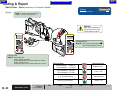
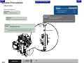
Check Valve
Go To Page:
Refer to:
Page
Cleaning ............................................... B-23
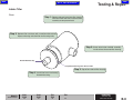
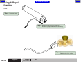
Function and Location
Exploded views .................................... E-1
The manifold check valve allows pressurized air to flow into the storage
tank when the compressors are running. The valve closes and does not
allow air flow during the purge cycle. Remove cap on top of manifold block
access the check valve.
B-22
Check Valve
© Midmark Corporation 2007 SF-1899 Rev 7/14
Next
Go To Table Of Contents
Models:
Serial Numbers:
All
www.midmark.com:
Manifold Check Valve
File Name
Replacement ............................. 10541600
Back
Next
Go To Table Of Contents
Testing & Repair
Check Valve
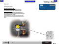
Step 1: Disconnect power.
Cleaning
Step 2: Remove manifold cap.
Remove check valve.
Note: Use Ratchet with extension and 3/4" socket to loosen valve.
Use needle nose pliers to lift check valve out of block.
Step 3: Blow out valve with air to clean.
Replace valve if it is sticking.
AA191200
Models:
Serial Numbers:
All
Check Valve
© Midmark Corporation 2007 SF-1899
B-23
Back
Next
Go To Table Of Contents
Testing & Repair
On/Off Switches
Go To Page:
Refer to:
Page
Testing ............................................... B-25
Wire Diagrams ...................................... D-1
Function and Location
The On/Off switch send power to the compressor heads.
Each compressor head has an On/Off switch.
Exploded views ..................................... E-1
AA191900
B-24
On/Off Switch
© Midmark Corporation 2007 SF-1899
Models:
Serial Numbers:
All
Back
Next
Go To Table Of Contents
On/Off Switch
Step 2: Set meter to V.
Testing
Testing & Repair
Go To Page:
Refer to:
Page
Access Procedures ............................... C-1
Wire Diagrams ...................................... D-1
Step 1: Remove electrical box cover.
Refer to: Section C Electrical Box
Caution
When testing components
with power on use care to
prevent electrical shock.
Step 4: Place meter probes on top right and top left side.
Step 3: Turn switch on.
Step 5: Place meter probes on bottom
right and bottom left side.
NOTE:
If all connections on top but one
are reading correct voltage when
there is multiple switches, check
jumper wire connections.
Meter Reading
Status
Required Action
230 Volt Models: < 230 Volts
Replace
115 Volt Models: < 115 Volts
On/Off Switch
Step 6: Turn switch off.
AA191300
230 Volt Models: 230 Volts
115 Volt Models: 115 Volts
Models:
Serial Numbers:
All
On/Off Switch - OK
On/Off Switch
© Midmark Corporation 2007 SF-1899
B-25
Back
Testing & Repair
Fuse
Go To Page:
Refer to:
Page
Check ............................................... B-27
Function and Location
Exploded Views .................................... E-1
The fuse protects the low voltage control system
against overload failure, mainly short circuits.
It is located in the electrical box and accessed
on top of the electrical box.
B-26
Fuse
© Midmark Corporation 2007 SF-1899
Next
Go To Table Of Contents
Models:
Serial Numbers:
All
Back
Go To Table Of Contents
Fuse
Next
Testing & Repair
Go To Page:
Refer to:
Page
Function and Location .......................... B-26
Check
Step 1: Turn power off.
Step 2: Remove electrical box cover.
Refer to: Section C Electrical box cover
Step 4: Remove fuse from electrical box.
Push in and turn cap counter clockwise.
AA191600
Step 3: Remove terminal leads.
Test continuity. Set meter to Ω.
Place meter probes on both fuse terminals.
Note: Refer to table below.
Step 5: Visually check to see if fuse is burnt or broken.
Note: If fuse is burnt or broken replace with a 1/3 amp 250V Slo-Blo fuse.
AA202500
Meter Reading
Status
OL - off line
Required Action
Replace Fuse
1/3 amp 250V Slo-Blo fuse
Continuity checks ok
Visually looks ok
Models:
Serial Numbers:
Step 6: Reinstall into electrical box.
Push in and turn cap clockwise until it locks in place.
Fuse is Good
All
Fuse
© Midmark Corporation 2007 SF-1899
Rev 4/07
B-27
Back
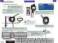
Testing & Repair
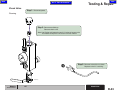
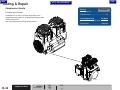
Start Relay
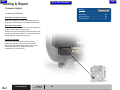
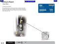
Function and Location
The start relay is located in the capacitor box. The start relay switches the load/current/voltage
from the start winding to the run winding as the rpm increases and load balance changes as
required to optimize the performance characteristics of the electric motor.
B-28
Start Relay
© Midmark Corporation 2007 SF-1899
Next
Go To Table Of Contents
Models:
Serial Numbers:
CL21
CL22
CL32
CL52
All
All
Go To Page:
Refer to:
Page
Testing ............................................... B-29
Wire Diagrams ...................................... D-1
Exploded views ..................................... E-1
Back
Next
Go To Table Of Contents
Testing & Repair
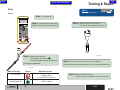
Start Relay
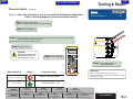
Testing
Step 1: Tap capacitor box.
Note: If motor starts, relay was stuck, replace relay.
2
5
Relay Test
Step 3: Test continuity. Set meter to Ω.
Place meter probes on contacts #2 & 5.
Note: # 2 & 5 are a resistance circuit.
Step 2: Unbolt capacitor assembly boxes
from platform. Remove front cover.
Meter Reading
AA192100
Models:
Serial Numbers:
CL32
CL52
CL21
CL22
All
All
Status
Required Action
"O" or "Open" Reading
Relay
Start Low and Increases
Relay - OK
Start Relay
© Midmark Corporation 2007 SF-1899
B-29
Back
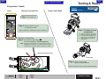
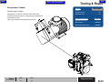
Testing & Repair
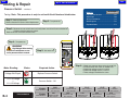
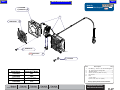
Compressor Heads
Go To Page:
Refer to:
Page
Check ............................................... B-31
Wiring Diagrams .................................... D-1
Function and Location
Exploded views ..................................... E-1
Atmospheric air is drawn in through intake filters to the
compressor head(s) where air is compressed and exhausted
to the reservoir (tank).
Heat is generated from the compression process.
Compressor Head
B-30
Models:
Serial Numbers:
© Midmark Corporation 2007 SF-1899
Next
Go To Table Of Contents
www.midmark.com:
File Name
Lubricated Head Replacement ....10542300
CL21
CL22
CL32
CL52
All
All
Back
Go To Table Of Contents
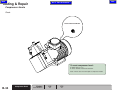
Compressor Heads
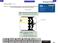
Check
Thermal Overload Test
Check Crank Shaft
Next
Testing & Repair
Go To Page:
Refer to:
Page
Access Procedures ............................... C-1
Step 1: Turn power off.
Step 2: Remove electrical cover
on compressor head.
Refer to Section C: Compressor Head - Electrical
Step 1: To drain oil from
compressor...
A.
Place a pan under the drain
plug, then remove drain plug.
B. Loosen front mounting nuts.
Remove rear mounting nuts.
C. Tip compressor forward to
drain all oil.
Thermal Overload Test
Step 3: Test continuity. Set meter to Ω.
Place meter probes on Thermal Overload.
Note: System is overheated if you have an Open Circuit
reading. Allow system to cool down and try to restart.
If system does not start, replace compressor heads.
Thermal Overload Protector
1
Crank Shaft
2
Step 2: Access Crank Shaft.
Verify crank shaft will turn.
R
C
Electrical Box on top of Compressor
Models:
Serial Numbers:
CL21
CL22
CL32
CL52
All
All
Note: If shaft will not turn, motor needs replaced.
S
AA192400
Compressor Head
© Midmark Corporation 2007 SF-1899
B-31
Back
Next
Go To Table Of Contents
Testing & Repair
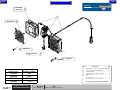
Compressor Heads
Go To Page:
Refer to:
Page
Wiring Diagrams .................................... D-1
Function and Location
Exploded views ..................................... E-1
Atmospheric air is drawn in through intake filters to the
compressor head(s) where air is compressed and exhausted
to the reservoir (tank).
Heat is generated from the compression process.
www.midmark.com:
File Name
Oil Less P21, P22 & P32 Head
Replacement .............................. 10567900
AA192500
Compressor Head
B-32
Models:
Serial Numbers:
© Midmark Corporation 2007 SF-1899
P21
P22
P32
All
All
Back
Go To Table Of Contents
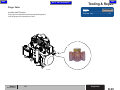
Compressor Heads
Next
Testing & Repair
Refer to:
Page
Go To Page:
Check ............................................... B-34
Function and Location
Atmospheric air is drawn in through intake filters to the
compressor head(s) where air is compressed and exhausted
to the reservoir (tank).
Heat is generated from the compression process.
Wiring Diagrams .................................... D-1
Exploded views ..................................... E-1
www.midmark.com:
File Name
Oil Less P52 & P72
Replacement .............................. 10485200
Reed Valve Replacment .............10499600
AA192600
Models:
Serial Numbers:
P52
P72
All
All
Compressor Head
© Midmark Corporation 2007 SF-1899
B-33
Back
Next
Go To Table Of Contents
Testing & Repair
Compressor Heads
Check
Thermal Overload Button
To reset compressor head...
AA192700
A. Allow motor to cool.
B. Press thermal overload reset button.
Note: If motor does not start replace compressor heads.
B-34
Compressor Head
© Midmark Corporation 2007 SF-1899
Models:
Serial Numbers:
P52
P72
All
All
Back
Go To Table Of Contents
Purge Valve
Next
Testing & Repair
Go To Page:
Refer to:
Page
Check ............................................... B-36
Exploded views .................................... E-1
Location and Function
The purge valve requlates the flow of purged/discharged air
from the purge tank to the desiccant tank.
AA194400
Models:
Serial Numbers:
All
Purge Valve
© Midmark Corporation 2007 SF-1899
B-35
Back
Next
Go To Table Of Contents
Testing & Repair
Purge Valve
Check
Step 1: Disconnect power.
Step 2: Remove air line tubing from purge valve.
Disconnect purge valve from purge tank fitting.
AA194500
Step 3: Blow out valve with air to clean.
Replace valve if it is sticking.
B-36
Purge Valve
© Midmark Corporation 2007 SF-1899
Models:
Serial Numbers:
All
Back
Next
Go To Table Of Contents
Testing & Repair
Thermal Overload Switch
Go To Page:
Refer to:
Page
Testing ............................................... B-38
Wiring Diagrams .................................... D-1
Location and Function
PowerAir® compressors motors are thermally protected also the control
circuit contains an automatic reset which shuts motors down if the
ambient temperature becomes too high. The switch is located on the
saddle behind and below the compressor heads.
Exploded views ..................................... E-1
Thermal Overload
Switch
WARNING
Compressor motors are thermally protected with
automatic reset and may restart without warning.
AA194000
Models:
Serial Numbers:
P21
All
P22
P32
P52
All
All
All
P72
All
Thermal Overload
Switch
© Midmark Corporation 2007 SF-1899
B-37
Back
Next
Go To Table Of Contents
Testing & Repair
Thermal Overload Switch
Go To Page:
Refer to:
Page
Access Procedures ............................... C-1
Wiring Diagrams .................................... D-1
WARNING
Testing
Compressor motors are thermally protected with
automatic reset and may restart without warning.
Exploded views ..................................... E-1
Step 1: Disconnect power to the compressor.
Step 2: Access electrical box.
Refer to: Section C Quiet Cover
ContinuityTest
Step 3: Test continuity. Set meter to Ω.
Disconnect switch at Transformer.
Place meter probes on ends of switch.
Attention:
To avoid compressor overheating and thermal shutdowns,
equipment room must be properly ventilated. Ambient
temperature should not exceed 104 ° Fahrenheit / 40° Celsius.
AA194200
Meter Reading
Status
"O" or "Open" Reading
Start Low and Increases
B-38
Thermal Overload
Switch
© Midmark Corporation 2007 SF-1899
Models:
Serial Numbers:
Rev 3/09
P21
P22
P32
P52
All
All
All
All
P72
All
Required Action
Replace Switch
Switch - OK
Back
Go To Table Of Contents
Quiet Cover - Fans (Accessory for PowerAir® Models)
The thermostat closes at 95° +/- 7°. The termostat opens
Wiring Diagrams .................................... D-1
Exploded views ..................................... E-1
at 70 degrees (+/- degrees).
Accessory for
PowerAir™ Model
77001603
77001604
77001605
77001606
P21
P22
P32 & P52
P72
Testing & Repair
Go To Page:
Refer to:
Page
Testing ............................................... B-40
Access Procedures ............................... C-1
Location and Function
Sound Cover
Next
NOTE: Quiet Cover assembly instructions
are provided with Quiet Cover.
AA193400
Models:
P21
P22
Serial Numbers:
P32
P52
P72
Quiet Cover - Fans
Accessory
Rev 8/10
© Midmark Corporation 2007 SF-1899
B-39
Back
Next
Go To Table Of Contents
Testing & Repair
Quiet Cover - Fans (Accessory for PowerAir® Models)
Testing
Go To Page:
Refer to:
Page
Access Procedures ............................... C-1
Step 1: Access fan electrical box.
Refer to: Section C Quiet Cover
Caution
When testing components
with power on use care to
prevent electrical shock.
ContinuityTest
Step 3: Test continuity. Set meter to Ω.
Place meter probes on switch.
Voltage Test
Step 2: Set meter to V.
AA193500
Check voltage at switch...
Place meter probes at fan connections on switch.
Check voltage at fans...
Unplug fan wires. Place meter probes on fan wires.
Meter Reading
230 Volt Models: < 230 Volts
Status
Required Action
Replace Fan(s)
115 Volt Models: < 115 Volts
230 Volt Models: 230 Volts
Fan(s) - OK
115 Volt Models: 115 Volts
B-40
Models:
Quiet Cover - Fans
© Midmark Corporation 2007 SF-1899
Serial Numbers:
Rev 8/10
P21
"C" or "Closed" Reading
Replace Switch
Start Low and Increases
Switch - OK
P22
P32
Accessory
P52
P72
Back
Next
Go To Table Of Contents
Section C
Access Procedures
Go To Page:
Removing & Installing:
Page
Check Valve ......................................... C-2
Electrical Box Cover ............................. C-3
Only Models CL21, CL22, CL32, CL52
Capacitor / Relay Box ........................... C-4
Compressor Head - Electrical Cover ..... C-5
Only Models P21, P22, P32, P52, P72
Quiet Cover Electrical Box (accessory) . C-6
Pressure Switch Cover.......................... C-7
Click GO TO PAGE: button (then enter desired page
number) to view any page in this document.
© Midmark Corporation 2007 SF-1899
C-1
Back
Next
Go To Table Of Contents
Access Procedures
Check Valve
Go To Page:
Refer To:
Page
Exploded Views / Part Numbers:
Removal/Installation
ClassicSeries®Models ........................ E-2
PowerAir® Models .............................. E-3
Removal
Step 1: Disconnect power.
Installation
Step 1: Install check valve into block.
Removal
Step 2: Drain air pressure from system.
Replace manifold cap.
Note: Use ratchet with extension and 3/4" socket to tighten valve.
Removal
Step 3: Remove manifold cap.
Manifold
Cap
Remove check valve.
Note: Use ratchet with extension and 3/4" socket to loosen valve.
Use needle nose pliers to lift check valve out of block.
Check Valve
Block
AA194700
C-2
Check Valve
© Midmark Corporation 2007 SF-1899
Models:
Serial Numbers:
All
Back
Next
Go To Table Of Contents
Access Procedures
Electrical Box Cover
Go To Page:
Refer To:
Page
Exploded Views / Part Numbers:
ClassicSeries®Models ........................ E-2
Removal/Installation
PowerAir® Models .............................. E-3
Removal
Step 1: Disconnect power.
Removal
Step 2: Remove screws.
Pull cover off.
Installation
Step 1: Secure cover on front of electrical box.
Install and tighten four screws through front cover.
AA194800
Models:
Serial Numbers:
All
Electrical Box Cover
© Midmark Corporation 2007 SF-1899
C-3
Back
Next
Go To Table Of Contents
Access Procedures
Capacitor/Relay Box (Lubricated Compressors)
Go To Page:
Refer To:
Page
Exploded Views / Part Numbers:
Removal/ Installation
ClassicSeries®Models ........................ E-2
Removal
Step 1: Disconnect power.
Removal
Step 2: Remove two screws from side of capacitor/relay box.
Pull cover off.
Installation
Step 1: Secure cover on front of capacitor/relay box.
Install and tighten two screws through side of cover.
AA194900
C-4
Capacitor / Relay Box
© Midmark Corporation 2007 SF-1899
Models:
Serial Numbers:
CL21
CL22
CL32
CL52
All
All
Back
Go To Table Of Contents
Next
Access Procedures
Compressor Head Electrical Cover (Lubricated Compressors)
Go To Page:
Refer To:
Page
Exploded Views / Part Numbers:
Removal/ Installation
ClassicSeries® Models ....................... E-2
Removal
Step 1: Disconnect power.
Removal
Step 2: Remove two screws from top of compressor head electrical box.
Pull cover off.
Installation
Step 1: Secure cover on top of compressor head electrical box.
Install and tighten two screws through top of cover.
AA195000
Models:
Serial Numbers:
CL21
CL22
CL32
CL52
All
All
Compressor Head
Electrical Box
© Midmark Corporation 2007 SF-1899
C-5
Back
Next
Go To Table Of Contents
Access Procedures
Sound Cover Electrical Box Cover (accessory)
Go To Page:
Refer To:
Page
Exploded Views / Part Numbers:
Removal/ Installation
PowerAir® Models .............................. E-3
Removal
Step 1: Disconnect power.
Removal
Step 2: Turn screws on top cover 1/4 turn counterclockwise.
Remove top cover.
Installation
Step 3: Install top panel.
Tighten by turning screws 1/4 turn clockwise.
Electrical Box Cover
Removal
Step 5: Remove electrical box cover
from the front side of back panel.
Installation
Step 1: Install electrical box cover in front of back panel.
Tighten screws in through back of back panel.
Removal
Step 4: Remove electrical box cover screws from back panel.
AA194300
Removal
Step 3: Remove back fan cover off back panel.
Installation
Step 2: Install back fan cover onto back panel.
C-6
Sound Cover Electrical
Box Cover
© Midmark Corporation 2007 SF-1899
Models:
Serial Numbers:
P21
All
P22
P32
P52
All
All
All
P72
All
Back
Next
Go To Table Of Contents
Access Procedures
Pressure Switch Cover
Go To Page:
Refer To:
Page
Exploded Views / Part Numbers:
Removal/Installation
ClassicSeries® Models ....................... E-2
PowerAir® Models .............................. E-3
Removal
Step 1: Disconnect power.
Removal
Step 2: Remove cap nut.
Pull cover off.
AA198200
Installation
Step 1: Place cover on pressure switch.
Secure cap nut.
Models:
Serial Numbers:
All
Pressure Switch Cover
© Midmark Corporation 2007 SF-1899
C-7
Back
Go To Table Of Contents
Next
Back
Next
Go To Table Of Contents
Section D
Wiring Diagrams
Model
ClassicSeries® Lubricated
Page
Go To Page:
CL21
CL22
............................................... D-2
............................................... D-5
CL32
CL52
............................................... D-8
............................................... D-11
PowerAir® - Oil Less
P21
............................................... D-14
P22
............................................... D-17
P32
............................................... D-20
P52
............................................... D-23
P72
............................................... D-26
Click GO TO PAGE: button (then enter desired page
number) to view any page in this document.
© Midmark Corporation 2007 SF-1899
D-1
Back
Next
Go To Table Of Contents
Wiring Diagrams
ClassicSeries® Lubricated Compressor
Single - 115 Volts
SOLENOID
VALVE
Wire
Harness
A
B
From:
To:
Part
Number
Power
Source
Contactor
62983000
Contactor
Fuse
BLK
BLK
*Common Ground
BLU
62979000
PUMP MOTOR
SPDT SWITCH
C
Pressure
Switch
Terminal
Block
62979100
Pressure
Switch
Contactor
62983700
E
Terminal
Block
Contactor
62979200
F
Hour
Meter
Cable
Contactor
Contactor
SPDT
Switch
H
Contactor
SPDT
Switch
62982400
I
SPDT
Switch
Motor
62982900
J
BLK
C
H
WHT
BLK
F
BLU
62982300
WHT
BLK
5
CAPACITOR AND RELAY ASSEMBLY
PRESSURE
SWITCH
Transformer
C
YEL
K
TERMINAL
BLOCK
RED
YEL
BLK
BLU
WHT
62983500
L
Termainal
Block
Low
Voltage
62983600
Low
Voltage
2
CAP
64884701
K
Termainal
Block
GRN/YEL*
YEL
D
A
YEL
HOURS
B
120 VAC
Motor
BLK
J
HOUR METER
Capacitor
and
Relay
Start
Winding
2
BLK
BLK
62979300
Low
Voltage
D-2
WHT
G
I
BLK
GRN/YEL*
Termainal
Block
M
WHT
CONTACTOR
D
G
WHT
Run Winding
M
BLU
AA183600
E
62983400
Wiring Diagrams
© Midmark Corporation 2007 SF-1899 Rev 8/09
Models:
Serial Numbers:
CL21
0701L210001 thru 0901L210370
L
Back
Go To Table Of Contents
Next
Wiring Diagrams
ClassicSeries® Lubricated Compressor
Single - 115 Volts
AA183601
Models:
Serial Numbers:
CL21
CL21
0902L210372 thru Present
V785000 thru V795263
Wiring Diagrams
© Midmark Corporation 2007 SF-1899 Rev 8/09
D-3
Back
Go To Table Of Contents
Wiring Diagrams
D-4
Models:
Wiring Diagrams
© Midmark Corporation 2007 SF-1899
Serial Numbers:
Rev 9/09
CL21
V795264 thru Present
Next
Back
Next
Go To Table Of Contents
Wiring Diagrams
ClassicSeries® Lubricated Compressor
Single - 230 Volts
SOLENOID
VALVE
Wire
Harness
BLK
From:
To:
Part
Number
A
Power
Source
Contactor
62978900
B
Contactor
Fuse
62979000
C
Pressure
Switch
Terminal
Block
62979100
D
Pressure
Switch
Contactor
62983700
E
Terminal
Block
Contactor
62979200
F
Hour
Meter
Cable
Contactor
62979300
G
Contactor
SPDT
Switch
62982500
H
Contactor
SPDT
Switch
62982400
I
SPDT
Switch
Motor
62982600
J
Motor
Capacitor
and
Relay
64884702
K
Terminal
Block
Low
Voltage
62983500
L
Terminal
Block
Low
Voltage
62983600
M
Terminal
Block
Low
Voltage
62983400
BLK
BLU
PUMP MOTOR
SPDT SWITCH
RED
RED
Run Winding
RED
G
C
CONTACTOR
I
BLK
BLK
2
BLK
H
Start
Winding
YEL
BLK
RED
BLK
J
BLK
GRN/YEL*
F
HOURS
B
BLU
WHT
HOUR METER
GRN/YEL*
YEL
BLK
2
CAP
D
A
5
CAPACITOR AND RELAY ASSEMBLY
230VAC
PRESSURE
SWITCH
Transformer
C
YEL
K
TERMINAL
BLOCK
RED
ORN
YEL
BLU
L
WHT
*Common Ground
BLU
E
Models:
Serial Numbers:
CL22
0701L220001 thru 0903L220294
M
AA183700
Wiring Diagrams
© Midmark Corporation 2007 SF-1899
Rev 8/09
D-5
Back
Next
Go To Table Of Contents
Wiring Diagrams
ClassicSeries®Lubricated Compressor
Single - 230 Volts
D-6
Models:
Wiring Diagrams
© Midmark Corporation 2007 SF-1899
Serial Numbers:
Rev 9/09
CL22
0903L220296 thru 0907L220318
CL22
V785000 thru V795558
Back
Go To Table Of Contents
Models:
Serial Numbers:
CL22
V795559 thru Present
CL22
0907L220319 thru Present
Next
Wiring Diagrams
Wiring Diagrams
© Midmark Corporation 2007 SF-1899
Rev 9/09
D-7
Back
Next
Go To Table Of Contents
Wiring Diagrams
ClassicSeries® Lubricated Compressor
Dual - 230 Volts
Wire
Harness
A
From:
To:
Part
Number
Power
Source
Contactor
62978900
SOLENOID
VALVE
PUMP MOTOR
SPDT SWITCH
BLK
RED
RED
C
BLK
B
Contactor
Fuse
62979000
C
Pressure
Switch
Terminal
Block
62979100
K
BLU
BLK
RED
Pressure
Switch
Contactor
62983700
RED
E
F
G
H
I
J
K
Terminal
Block
Contactor
62979200
Start
Winding
2
H
Hour
Meter
Cable
Contactor
BLK
GRN/YEL*
Contactor
Contactor
SPDT
Switch
Motor
Motor
B
SPDT
Switch
62982500
SPDT
Switch
62982400
Motor
62982600
WHT
BLK
GRN/YEL*
YEL
2
CAP
D
A
CAPACITOR AND RELAY ASSEMBLY
HOURS
HOUR METER
BLU
64884702
SPDT
Switch
62982700
*Common Ground
5
CAPACITOR AND RELAY ASSEMBLY
230VAC
PRESSURE
SWITCH
Transformer
C
TERMINAL
BLOCK
Capacitor
and
Relay
5
YEL
J
F
ORN
YEL
L
RED
BLU
M
WHT
Low
Voltage
62983500
M
Terminal
Block
Low
Voltage
62983600
N
Terminal
Block
Low
Voltage
62983400
Wiring Diagrams
© Midmark Corporation 2007 SF-1899 Rev 8/09
N
BLU
E
Terminal
Block
Models:
Serial Numbers:
2
CAP
BLK
BLK
62979300
GRN/YEL*
BLK
RED
L
D-8
C
I
BLK
BLK
J
Run Winding
RED
G
CONTACTOR
YEL
BLK
RED
PUMP MOTOR
SPDT SWITCH
RED
Start
Winding
2
BLK
BLK
D
Run Winding
AA183800
CL32
0701L320001 thru 0901L320807
Back
Go To Table Of Contents
Next
Wiring Diagrams
ClassicSeries® Lubricated Compressor
Dual - 230 Volts
Models:
Serial Numbers:
CL32
CL32
0901L320813 thru 0906L320846
V785000 thru V795281
Wiring Diagrams
© Midmark Corporation 2007 SF-1899 Rev 9/09
D-9
Back
Wiring Diagrams
D-10
Models:
Wiring Diagrams
© Midmark Corporation 2007 SF-1899
Serial Numbers:
Rev 9/09
Next
Go To Table Of Contents
CL32
CL32
V795282 thru Present
0906L320847 thru Present
Back
Next
Go To Table Of Contents
Wiring Diagrams
ClassicSeries® Lubricated Compressor
Triple - 230 Volts
Wire
Harness
From:
To:
Part
Number
A
Power
Source
Contactor
62978900
B
Contactor
Fuse
62979000
C
Pressure
Switch
Terminal
Block
62979100
D
Pressure
Switch
Contactor
62983700
E
Terminal
Block
Contactor
62979200
F
Hour
Meter
Cable
Contactor
62979300
G
Contactor
SPDT
Switch
62982500
H
Contactor
SPDT
Switch
62982400
I
SPDT
Switch
Motor
62982600
J
Motor 1
Capacitor
and
Relay
64884702
K
Motor 2
SPDT
Switch
62982700
L
Motor 3
SPDT
Switch
62982800
M
Terminal
Block
Low
Voltage
62983500
N
Terminal
Block
Low
Voltage
62983600
O
Terminal
Block
Low
Voltage
62983400
PUMP MOTOR
SPDT SWITCH
Run Winding
RED
RED
C
L
2
BLK
BLK
SOLENOID
VALVE
SPDT SWITCH
K
BLK
2
H
SPDT SWITCH
BLK
C
I
Start
Winding
2
BLK
GRN/YEL*
BLK
A
WHT
5
YEL
BLK
CAPACITOR AND RELAY ASSEMBLY
J
F
HOURS
HOUR METER
BLU
2
CAP
RED
BLK
B
CAPACITOR AND RELAY ASSEMBLY
Run Winding
RED
GRN/YEL*
BLK
GRN/YEL*
YEL
D
*Common Ground
2
CAP
5
CAPACITOR AND RELAY ASSEMBLY
PRESSURE
SWITCH
230VAC
C
Transformer
ORN
YEL
RED
BLU
WHT
AA183900
E
Models:
M
YEL
TERMINAL
BLOCK
BLU
Serial Numbers:
2
5
YEL
J
PUMP MOTOR
RED
BLK
GN/YL*
CAP
RED
BLK
BLK
Start
Winding
BLK
G
RED
YEL
J
C
BLK
CONTACTOR
BLK
Run Winding
RED
RED
RED
RED
PUMP MOTOR
BLK
BLU
Start
Winding
CL52
0701L520001 thru 0810CL520124
N
O
Wiring Diagrams
© Midmark Corporation 2007 SF-1899
Rev 8/09
D-11
Back
Next
Go To Table Of Contents
Wiring Diagrams
ClassicSeries® Lubricated Compressor
Triple - 230 Volts
D-12
Models:
Wiring Diagrams
© Midmark Corporation 2007 SF-1899
Serial Numbers:
Rev 9/09
CL52
0810L520126 thru 0907L520142
CL52
V785000 thru V795341
Back
Go To Table Of Contents
Models:
Serial Numbers:
CL52
V795342 Thru Present
CL52
0907L520143 thru Present
Next
Wiring Diagrams
Wiring Diagrams
© Midmark Corporation 2007 SF-1899
Rev 9/09
D-13
Back
Next
Go To Table Of Contents
Wiring Diagrams
PowerAir® Oil Less Compressor
Dual - 115 Volts
Wire
Harness
From:
To:
Part
Number
A
Power Source
Contactor
62983000
B
Contactor
Fuse
62979000
C
Pressure
Switch
Terminal Block
62979100
Capacitor
BRN
Fans Included with Quiet Cover Option Only
Thermal
Switch
BLK
Q
BRN/WHT
P
Q
SPDT SWITCH
WHT
F
I
WHT
PUMP MOTOR
BLK
D
Contactor
Terminal Block
62979200
E
Hour Meter
Cable
Contactor
62979300
F
SPDT Switch
SPDT Switch
62982300
G
SPDT Switch
SPDT Switch
62982400
H
Motor (Single)
SPDT Switch
62985000
G
P
RED
O
BLK
BLK
Capacitor
GRN/YEL*
Connector
BLK
BRN
N
BRN/WHT
SOLENOID
VALVE
BLU
SPDT SWITCH
WHT
WHT
I
SPDT Switch
Motor (Dual)
62984700
J
Contactor
Pressure Switch
62983700
K
Terminal Block
Low Voltage
62983400
L
Terminal Block
Low Voltage
62983500
F
WHT
G
BLK
CONTACTOR
H
BLK
BLK
PUMP MOTOR
BLK
B
GRN/YEL*
BLK
E
GRN/YEL*
HOURS
M
Terminal Block
Low Voltage
62983600
N
Compressor
Plug
Contactor
62984000
O
Quiet Cover
Plug
Terminal Block &
Thermal Switch
BLU
WHT
BLK
YEL
A
HOUR METER
J
PRESSURE
SWITCH
Transformer
C
TERMINAL
BLOCK
62984500
BLK
P
Fan Power
Cord
Terminal Block
62984600
Q
Thermal
Switch
Terminal Block
62983900
D-14
Serial Numbers:
Rev 8/09
D
RED
BLU
P21
0703P210001 thru 0903P210361
RED
BLU
YEL
*Common Ground
Models:
Wiring Diagrams
© Midmark Corporation 2007 SF-1899
120 VAC
L
YEL
Thermal
Switch
RED
WHT
K
M
AA184100
Back
Go To Table Of Contents
Next
Wiring Diagrams
PowerAir® Oil Less Compressor
Dual - 115 Volts
Models:
Serial Numbers:
P21
P21
0904P210365 thru Present
V785000 thru V795263
Wiring Diagrams
© Midmark Corporation 2007 SF-1899
D-15
Rev 8/09
Back
Go To Table Of Contents
Wiring Diagrams
D-16
Models:
Wiring Diagrams
© Midmark Corporation 2007 SF-1899
Serial Numbers:
Rev 9/09
P21
V795264 thru Present
Next
Back
Next
Go To Table Of Contents
Wiring Diagrams
Capacitor
PowerAir® Oil Less Compressor
Dual - 208-230 Volts
BRN
BRN/WHT
Fans Included with Quiet Cover Option Only
BLK
Thermal
Switch
P
Q
SPDT SWITCH
RED
RED
I
F
O
P
RED
G
BLU
PUMP MOTOR
BLK
From:
To:
Part
Number
A
Power Source
Contactor
62978900
B
Contactor
Fuse
62979000
C
Pressure
Switch
Terminal Block
62979100
D
Contactor
Terminal Block
62979200
E
Hour Meter
Cable
Contactor
62979300
F
SPDT Switch
SPDT Switch
62982500
G
SPDT Switch
SPDT Switch
62982400
H
Motor (Single)
SPDT Switch
62985100
I
SPDT Switch
Motor (Dual)
62984800
J
Contactor
Pressure Switch
62983700
K
Terminal Block
Low Voltage
62983400
L
Terminal Block
Low Voltage
62983500
M
Terminal Block
Low Voltage
62983600
N
Compressor
Plug
Contactor
62984000
O
Quiet Cover
Plug
Terminal Block &
Thermal Switch
62984500
P
Fan Power
Cord
Terminal Block
62984600
Q
Thermal
Switch
Terminal Block
62983900
Capacitor
BLU
Connector
Wire
Harness
GRN/YEL*
BLK
BRN
N
BRN/WHT
SOLENOID
VALVE
BLU
SPDT SWITCH
RED
F
CONTACTOR
RED
RED
H
BLK
G
BLK
PUMP MOTOR
BLK
BLK
BLU
BLK
B
GRN/YEL*
WHT
BLK
E
GRN/YEL*
HOURS
YEL
HOUR METER
J
A
PRESSURE
SWITCH
Transformer
C
YEL
TERMINAL
BLOCK
ORN
L
RED
BLU
230 VAC
YEL
RED
Thermal
Switch
RED
WHT
M
*Common Ground
BLU
D
Models:
Serial Numbers:
K
AA184200
P22
0703P220001 thru 0903P221139
Wiring Diagrams
© Midmark Corporation 2007 SF-1899 Rev 8/09
D-17
Back
Next
Go To Table Of Contents
Wiring Diagrams
PowerAir® Oil Less Compressor
Dual - 208-230 Volts
D-18
Models:
Wiring Diagrams
© Midmark Corporation 2007 SF-1899
Serial Numbers:
Rev 9/09
P22
P22
0904P221146 thru 0908P221308
V785000 thru V795263
Back
Go To Table Of Contents
Models:
Serial Numbers:
P22
P22
V795264 thru Present
0908P221309 thru Present
Next
Wiring Diagrams
Wiring Diagrams
© Midmark Corporation 2007 SF-1899 Rev 9/09
D-19
Back
Next
Go To Table Of Contents
Wiring Diagrams
PowerAir™ Oil Less Compressor
Triple- 208-230 Volts
Capacitor
BRN
Wire
Harness
From:
To:
Part
Number
A
Power Source
Contactor
62978900
BRN/WHT
SPDT SWITCH
RED
Fans Included with Quiet Cover Option Only
B
C
Contactor
Pressure
Switch
Fuse
62979000
F
Thermal
Switch
Q
Q
Terminal Block
P
D
Contactor
Terminal Block
62979200
E
Hour Meter
Cable
Contactor
62979300
G
F
SPDT Switch
SPDT Switch
62982500
G
SPDT Switch
SPDT Switch
62982400
H
Motor (Single)
SPDT Switch
62985100
I
SPDT Switch
Motor (Dual)
62984800
O
P
RED
BRN
BLU
BRN/WHT
BLU
SPDT SWITCH
RED
RED
N
SOLENOID
VALVE
BLU
Terminal Block
Low Voltage
BLK
I
PUMP MOTOR
BLK
Capacitor
RED
RED
F
GRN/YEL*
62983700
BRN
BLK
K
Capacitor
GRN/YEL*
CONTACTOR
Pressure Switch
PUMP MOTOR
BLK
Connector
Contactor
R
62979100
BLK
J
BLK
RED
BLK
G
62983400
BRN/WHT
BLK
L
M
Terminal Block
Terminal Block
Low Voltage
Low Voltage
62983500
SPDT SWITCH
62983600
O
P
Compressor
Plug
WHT
BLK
Contactor
BLK
YEL
HOUR
Terminal Block &
Thermal Switch
62984500
Fan Power
Cord
Terminal Block
62984600
A
PUMP MOTOR
C
J
Quiet Cover
Plug
H
METER
62984000
PRESSURE
SWITCH
GRN/YEL*
YEL
L
Transformer
TERMINAL
BLOCK
RED
ORN
230 VAC
Q
Thermal
Switch
Terminal Block
62983900
R
Motor (Triple)
SPDT Switch
62984900
D-20
E
HOURS
BLU
N
RED
B
GRN/YEL*
BLK
Wiring Diagrams
© Midmark Corporation 2007 SF-1899 Rev 8/09
Models:
Serial Numbers:
BLU
YEL
RED
*Common Ground
D
BLU
P32
0703P320001 thru 0903P321137
Thermal
Switch
RED
WHT
K
M
AA184300
Back
Next
Go To Table Of Contents
Wiring Diagrams
PowerAir® Oil Less Compressor
Triple- 208-230 Volts
Models:
Serial Numbers:
P32
0904P321145 thru 0909P321336
P32
P32
V785000 thru V795559
0909P321337 thru Present
Wiring Diagrams
© Midmark Corporation 2007 SF-1899 Rev 8/09
D-21
Back
Go To Table Of Contents
Wiring Diagrams
D-22
Wiring Diagrams
© Midmark Corporation 2007 SF-1899 Rev 9/09
Models:
Serial Numbers:
P32
V7955560 thru Present
Next
Back
Next
Go To Table Of Contents
Wiring Diagrams
PowerAir® Oil Less Compressor
Dual Cattani Head - 208-230 Volts
Fans Included with Quiet Cover Option Only
BLK
O
Thermal
Switch
P
Q
Connector
BLU
(Capacitor)
V1
2
1
Part
Number
A
Power Source
Contactor
62978900
B
Contactor
Fuse
62979000
C
Pressure
Switch
Terminal Block
62979100
D
Contactor
Terminal Block
62979200
E
Hour Meter
Cable
Contactor
62979300
F
SPDT Switch
SPDT Switch
62982500
G
SPDT Switch
SPDT Switch
62982400
H
Motor (Single)
SPDT Switch
62982600
I
SPDT Switch
Motor (Dual)
62982700
J
Contactor
Pressure Switch
62983700
K
Terminal Block
Low Voltage
62983400
L
Terminal Block
Low Voltage
62983500
M
Terminal Block
Low Voltage
62983600
N
Compressor
Plug
Contactor
62984000
O
Quiet Cover
Plug
Terminal Block &
Thermal Switch
62984500
P
Fan Power
Cord
Terminal Block
62984600
Q
Thermal
Switch
Terminal Block
62983900
Thermal
Protector
2
1
BLK
I
W1
RED
F
SOLENOID
VALVE
BLU
W2 U2 V2
U1
RED
N
BLK
RED
RED
Circuit
Breakers
F
CONTACTOR
GRN/YEL*
G
BLK
BLK
G
PUMP MOTOR
(Capacitor)
BLK
Thermal
Protector
2
HOUR
H
1
BLK
YEL
2
1
HOURS
BLK
W1
E
V1
J
BLK
W2 U2 V2
U1
SPDT SWITCH
RED
B
WHT
To:
PUMP MOTOR
SPDT SWITCH
BLU
From:
RED
BLU
GRN/YEL*
Wire
Harness
METER
Circuit
Breakers
C
PRESSURE
SWITCH
A
YEL
GRN/YEL*
Transformer
TERMINAL
BLOCK
ORN
L
RED
BLU
230 VAC
YEL
RED
RED
Thermal
Switch
*Common Ground
D
BLU
M
WHT
K
AA184500
Models:
Serial Numbers:
P52
0701P520001 thru 0902P520467
Wiring Diagrams
© Midmark Corporation 2007 SF-1899
Rev 9/09
D-23
Back
Next
Go To Table Of Contents
Wiring Diagrams
PowerAir® Oil Less Compressor
Dual Cattani Head - 208-230 Volts
D-24
Models:
Wiring Diagrams
© Midmark Corporation 2007 SF-1899
Serial Numbers:
Rev 9/09
P52
0904P520474 thru 0908P520572
P52
V785000 thru V795561
Back
Go To Table Of Contents
Models:
Serial Numbers:
P52
P52
V795562 thru Present
0908P520573 thru Present
Next
Wiring Diagrams
Wiring Diagrams
© Midmark Corporation 2007 SF-1899 Rev 9/09
D-25
Back
Next
Go To Table Of Contents
Wiring Diagrams
PowerAir® Oil Less Compressor
Triple Cattani Head - 208-230 Volts
62978900
B
Contactor
Fuse
62979000
C
Pressure
Switch
Terminal Block
62979100
D
Contactor
Terminal Block
62979200
E
Hour Meter
Cable
Contactor
F
SPDT Switch
SPDT Switch
62982500
G
SPDT Switch
SPDT Switch
62982400
Q
R
Thermal
Protector
2
Contactor
BLK
2
Power Source
F
P
Q
1
A
RED
1
BLK
Thermal
Switch
SPDT SWITCH
RED
W2 U2 V2
Fans Included with Quiet Cover Option Only
W1
To:
Part
Number
U1
From:
(Capacitor)
V1
Wire
Harness
PUMP MOTOR
BLK
Circuit
Breakers
O
GRN/YEL*
G
P
RED
BLU
Connector
PUMP MOTOR
(Capacitor)
U1
V1
SPDT SWITCH
RED
1
RED
SOLENOID
VALVE
BLU
I
Thermal
Protector
2
1
BLK
2
N
W1
62979300
W2 U2 V2
BLU
BLK
H
Motor (Single)
SPDT Switch
RED
62982600
SPDT Switch
Motor (Dual)
BLK
62982700
BLK
B
62983400
SPDT SWITCH
RED
E
GRN/YEL*
HOURS
Low Voltage
62983500
M
Terminal Block
Low Voltage
62983600
N
Compressor
Plug
Contactor
Quiet Cover
Plug
Terminal Block &
Thermal Switch
O
62984000
Q
Thermal
Switch
Terminal Block
62983900
R
Motor (Triple)
SPDT Switch
62982800
D-26
J
© Midmark Corporation 2007 SF-1899
Thermal
Protector
METER
A
PRESSURE
SWITCH
C
Models:
Serial Numbers:
GRN/YEL*
TERMINAL
BLOCK
ORN
62984600
YEL
Transformer
RED
L
BLU
YEL
RED
RED
Thermal
Switch
*Common Ground
D
Wiring Diagrams
H
Circuit
Breakers
230 VAC
Fan Power
Cord
BLK
YEL
HOUR
62984500
P
Terminal Block
BLK
2
Terminal Block
WHT
1
L
BLU
2
Low Voltage
W2 U2 V2
Terminal Block
(Capacitor)
62983700
1
K
PUMP MOTOR
W1
Pressure Switch
G
BLK
V1
Contactor
GRN/YEL*
U1
J
F
CONTACTOR
BLK
I
Circuit
Breakers
RED
BLU
WHT
M
K
AA184600
P72
0701P720001 thru 0903P720190
Back
Go To Table Of Contents
Next
Wiring Diagrams
PowerAir® Oil Less Compressor
Triple Cattani Head - 208-230 Volts
Models:
Serial Numbers:
P72
P72
0903P720191 thru 0909P720227
V785000 thru V795511
Wiring Diagrams
© Midmark Corporation 2007 SF-1899 Rev 9/09
D-27
Back
Wiring Diagrams
D-28
Models:
Wiring Diagrams
© Midmark Corporation 2007 SF-1899
Serial Numbers:
Rev 9/09
Next
Go To Table Of Contents
P72
V795512 thru Present
P72
0909P720228 thru Present
Back
Next
Section E
Go To Table Of Contents
Exploded Views &
Parts Lists
Go To Page:
Model:
Page
®
ClassicSeries .................................................................... E-2
PowerAir® ................................................................................. E-3
Click GO TO PAGE: button (then enter desired page
number) to view any page in this document.
© Midmark Corporation 2006 SF-1899
E-1
Back
ClassicSeries
CL21
CL22
CL32
CL52
Next
Go To Table Of Contents
®
Installation Kit
CL21, C22 ..................E-4*
CL32, CL52 ................E-5*
Label Locations ........E-26*
Pneumatic Tubes and Hoses
CL21, CL22 ................E-16
CL32 ..........................E-17
CL52 ..........................E-18
Compressor
Heads ........................E-25
Electrical
Control Box .............. E-15*
Tanks & Main Components ........E-12
Check Valve
Manifold Assembly. .E-13
AA195200
Coalescing Filter
Assembly .................. E-14
E-2
* Indicates multiple pages due to a model / serial number break for the parts illustration
© Midmark Corporation 2006 SF-1899 Rev. 7/14
Back
PowerAir
P21
P22
P32
P52
P72
Next
Go To Table Of Contents
®
Label Locations ........ E-26*
Installation Kit
P21, P22, P32 ........... E-7*
P52 ............................E-9*
P72 ............................E-10*
Sound Covers (Accessory)...E-27
Compressor Heads
P21, P22, P32 ............E-23
P52, P72 ....................E-24
Electrical
Control Box ..............E-15*
Tanks & Main Components ........E-12
Coalescing Filter
Assembly ..................E-14
AA195300
Pneumatic Tubes and Hoses
P21, P22 ....................E-19
P32 ............................E-20
P52 ............................E-21
P72 ............................E-22
Check Valve
Manifold Assembly. . E-13
* Indicates multiple pages due to a model / serial number break for the parts illustration
E-3
© Midmark Corporation 2006 SF-1899 Rev. 7/14
Back
Next
Go To Table Of Contents
20199000
3
20218500
PCT80450-13
77001391
2
1
PVC50718
65977700
002-1804-00
Note: Refer to Date listed below. Must
use Kit # 20221000 for any Units built
August of 2008 to Present.
4
6
7 PVC51123
15
77002134
8
62900106
14
Note: Elbow was not
present on early units.
1
2
3
4
5
6
7
8
9
10
11
12
13
14
15
BMS20900
12 MRP70967
13
65977600
Item
9
040-0312-00
Items # 4, 5, 7, 8, 9, and 10 are only
available though Midmark for compressors under warranty. If compressor is out of warranty these items are
available at your local hardware store,
if needed for service.
5
10 BSW20472
11 62983300
AA196400
16
17
Description
Qty.
20199000 Kit (includes items 1 - 18)
• Fresh Air Intake Hose (1/2") (no fittings) . 1
• Drain Hose (16' [sold by the inch]) ........ AR
• Operatory High Pressure Hose Assy ...... 1
• SL PVC Tee (2") ........................................ 1
• Nipple (1/2" MNPT x 1/4" NPT) ................ 1
• Filter Assembly Kit .................................... 1
• PVC Bushing (2" x 1/2") ............................ 2
• Brass Hose, Barb (1/2' MPT x 1/4") ........ 1
• Wall Anchor (3/16" x 1-1/4") ..................... 2
• Screw (#8 x 1 1/2") ................................... 2
• Exhaust Silencer ....................................... 1
• Rubber Foot .............................................. 4
• Bolt (5/16-18" x 1/2"") ............................... 4
• Elbow (45 Deg Street (1/2" NPT) ............. 1
•I ndicator ..................................................... 1
Not Shown - 62988004
• Pipe Hanger (2") ........................................ 1
• Oil ............................................................... 1
Always Specify Model & Serial Number
E-4
Installation Kit
© Midmark Corporation 2007 SF-1899 Rev. 7/28/14
Models:
CL21
CL22
Serial Numbers: Up to July 2008 Up to July 2008
Back
Next
Go To Table Of Contents
20199100
3
20218500
PCT80450-13
77001391
2
1
Note: Refer to Date listed below. Must
use Kit # 20221000 for any Units buit
after the listed.
PVC50720
65977700
77002134
15
4
5
6
002-1804-00
Items # 4, 5, 7, 8, 9, and 10 are only
available though Midmark for compressors under warranty. If compressor is out of warranty these items are
available at your local hardware store,
if needed for service.
7
PVC51123
Item
8
62900106
14
12 MRP70967
040-0312-00
1
2
3
4
5
6
7
8
9
10
11
12
13
14
15
Note: Elbow was not
present on early units.
9
65977600
BMS20900
10 BSW20472
13
11 62983300
16
17
Description
Qty.
20199100 Kit (includes items 1 - 18)
• Fresh Air Intake Hose (1/2") (no fittings) . 1
• Drain Hose (16' [sold by the inch]) ........ AR
• Operatory High Pressure Hose Assy ...... 1
• SL PVC Cross (2") .................................... 1
• Nipple (1/2" MNPT x 1/4" NPT) ................ 2
• Filter Assembly Kit .................................... 2
• PVC Bushing (2" x 1/2") ............................ 3
• Brass Hose, Barb (1/2' MPT x 1/4") ........ 1
• Wall Anchor (3/16" x 1-1/4") ..................... 2
• Screw (#8 x 1 1/2") ................................... 2
• Exhaust Silencer ....................................... 1
• Rubber Foot .............................................. 4
• Bolt (5/16-18" x 1/2"") ............................... 4
• Elbow (45 Deg Street (1/2" NPT) ............. 1
•I ndicator with O-Rings .............................. 1
Not Shown - 62988004
• Pipe Hanger (2") ........................................ 1
• Oil ............................................................... 1
AA196500
Always Specify Model & Serial Number
Models:
Serial Numbers:
CL52
CL32
Up to July 2008
Up to July 2008
Installation Kit
© Midmark Corporation 2007 SF-1899 Rev. 7/28/14
E-5
Go To Table Of Contents
Back
Next
20221000
1
61900912
62963203
9
2 77001391
77002134
8
7
62900106
3 62945400
Item
5 MRP70967
040-0312-00
4
62983300
1
2
3
4
5
6
7
8
9
6
AA223100
10
Description
Qty.
20221000 Kit (includes items 1 - 10)
• Hose x (1") MPT, Conn (3/4") .................. 1
• Operatory High Pressure Hose Assy ...... 1
• Adapter, Female (1" ID x 1" NPT) ............ 1
• Exhaust Silencer ....................................... 1
• Rubber Foot .............................................. 4
• Bolt (5/16-18" x 1/2"") ............................... 4
• Elbow 45 Deg Street (1/2" NPT) ............... 1
• Indicator with O-Rings .............................. 1
• Conn, (3/4" Hose x 1" MPT) ..................... 1
Not Shown - 77000955
• Oil ............................................................... 1
Always Specify Model & Serial Number
E-6
Models:
Installation Kit
© Midmark Corporation 2007 SF-1899
Serial Numbers:
Rev 4/14
CL21
CL22
CL52
CL32
Built August 2008
thru Present
Built August 2008
thru Present
Built August 2008
thru Present
Built August 2008
thru Present
Back
Next
Go To Table Of Contents
20199600
3
20218500
PCT80450-13
77001391
2
1
6 002-1804-00
65977700
PVC50720
5
Note: Refer to Date listed below. Must
use Kit # 20220900 for any Units built
August of 2008 to Present.
4
7
77002134
15
62900106
14
8
65977600
Note: Elbow was not
present on early units.
Item
9
BMS20900
12 MRP70967
040-0312-00
Items # 4, 5, 7, 8, 9, and 10 are only
available though Midmark for compressors under warranty. If compressor is out of warranty these items are
available at your local hardware store,
if needed for service.
PVC51123
10
BSW20472
13
11
62983300
AA196000
1
2
3
4
5
6
7
8
9
10
11
12
13
14
15
16
Description
Qty.
20199600 Kit (includes items 1 - 17)
• Fresh Air Intake Hose (1/2") (no fittings) . 1
• Drain Hose (16' [sold by the inch]) ........ AR
• Operatory High Pressure Hose Assy ...... 1
• SL PVC Cross (2") .................................... 1
• Nipple (1/2" MNPT x 1/4" NPT) ................ 2
• Filter Assembly Kit .................................... 2
• PVC Bushing (2" x 1/2") ............................ 3
• Brass Hose, Barb (1/2' MPT x 1/4") ........ 1
• Wall Anchor (3/16" x 1-1/4") ..................... 2
• Screw (#8 x 1 1/2") ................................... 2
• Exhaust Silencer ....................................... 1
• Rubber Foot .............................................. 4
• Bolt (5/16-18" x 1/2"") ............................... 4
• Elbow (45 Deg Street (1/2" NPT) ............. 1
• Indicator with O-Rings .............................. 1
Not Shown - 62988004
• Pipe Hanger (2") ........................................ 1
Always Specify Model & Serial Number
Models:
Serial Numbers:
P21
Up to July 2008
P22
P32
Up to July 2008
Up to July 2008
Installation Kit
© Midmark Corporation 2007 SF-1899 Rev 7/28/14
E-7
Back
Next
Go To Table Of Contents
20220900
1
61900912
62963203
9
77002134
8
62900106
7
2
77001391
3
62945400
Item
5
040-0312-00
MRP70967
4
1
2
3
4
5
6
7
8
9
62983300
6
Description
Qty.
220220900 Kit (includes items 1 - 9)
• Hose x (1") MPT, Conn (3/4") .................. 1
• Operatory High Pressure Hose Assy ...... 1
• Adapter, Female (1" ID x 1" NPT) ............ 1
• Exhaust Silencer ....................................... 1
• Rubber Foot .............................................. 4
• Bolt (5/16-18" x 1/2"") ............................... 4
• Elbow (45 Deg Street (1/2" NPT) ............. 1
• Indicator with O-Rings .............................. 1
• Conn, (3/4" Hose x 1" MPT) ..................... 1
AA223200
Always Specify Model & Serial Number
E-8
Models:
Installation Kit
© Midmark Corporation 2007 SF-1899
Serial Numbers:
Rev 4/11
P21
Built August 2008
thru Present
P22
Built August 2008
thru Present
P32
Built August 2008
thru Present
Back
Next
Go To Table Of Contents
20199300
3
20218500
65962201
77001391
2
1
Note: Refer to Date listed
below. Must use Kit #
20220800 for any Units built
August of 2008 to Present.
4 PVC50720
5 62900505
77002134
62900106
15
14
6 STK10500
Note: Elbow was not
present on early units.
Item
PVC51123
1
7
2
3
4
5
6
7
8
9
10
11
12
13
14
15
12 MRP70967
65977600
040-0312-00
13
8
9 BMS20900
11 62983300
Items # 4, 5, 7, 8, 9, and 10
are only available though
Midmark for compressors
under warranty. If compressor is out of warranty these
items are available at your
local hardware store, if
needed for service.
10 BSW20472
AA196300
16
Description
Qty.
20199300 Kit (includes items 1 - 16)
• Fresh Air Intake Hose (1/4" ID x 3/8" OD)
(no fittings) ................................................ 1
• Drain Hose (16' [sold by the inch]) ........ AR
• Operatory High Pressure Hose Assy ...... 1
• SL PVC Cross (2") .................................... 2
• Hex Nipple (1/2" NPT x 1/2" NPT) ........... 4
• PVC Pipe (2", SCH 40, 6" L) ..................... 1
• PVC Bushing (2" x 1/2" X FPT) ................ 5
• Brass Hose, Barb (1/2' MPT x 1/4") ........ 1
• Wall Anchor (3/16" x 1-1/4") ..................... 2
• Screw (#8 x 1 1/2") ................................... 2
• Exhaust Silencer ....................................... 1
• Rubber Foot .............................................. 4
• Bolt (5/16-18" x 1/2"") ............................... 4
• Elbow (45 Deg Street (1/2" NPT) ............. 1
• Indicator with O-Rings .............................. 1
Not Shown - 62988004
• Pipe Hanger (2") ........................................ 1
Always Specify Model & Serial Number
Models:
P52
Serial Numbers: Up to July 2008
Installation Kit
© Midmark Corporation 2007 SF-1899
E-9
Rev 4/11
Back
Next
Go To Table Of Contents
20199400
3
20218500
65962201
1
77001391
2
4 PVC50720
5
6
77002134
62900505
Note: Refer to Date listed below. Must
use Kit # 20220800 for any Units built
August of 2008 to Present.
STK10500
15
62900106
14
Items # 4, 5, 7, 8, 9, and 10 are only
available though Midmark for compressors under warranty. If compressor is out of warranty these items are
available at your local hardware store,
if needed for service.
Note: Elbow was not
present on early units.
PVC51123
7
Item
12 MRP70967
1
040-0312-00
2
3
4
5
6
7
8
9
10
11
12
13
14
15
13
9 BMS20900
65977600
8
11 62983300
10 BSW20472
AA196100
16
E-10
Installation Kit
© Midmark Corporation 2007 SF-1899 Rev 4/11
Models:
Serial Numbers:
P72
Up to July 2008
Description
Qty.
20199400 Kit (includes items 1 - 16)
• Fresh Air Intake Hose (1/4" ID x 3/8" OD)
(no fittings) ................................................ 2
• Drain Hose (16' [sold by the inch]) ........ AR
• Operatory High Pressure Hose Assy ...... 1
• SL PVC Cross (2") .................................... 3
• Hex Nipple (1/2" NPT x 1/2" NPT) ........... 6
• PVC Pipe (2", SCH 40, 6" L) ..................... 2
• PVC Bushing (2" x 1/2" X FPT) ................ 7
• Brass Hose, Barb (1/2' MPT x 1/4") ........ 1
• Wall Anchor (3/16" x 1-1/4") ..................... 2
• Screw (#8 x 1 1/2") ................................... 2
• Exhaust Silencer ....................................... 1
• Rubber Foot .............................................. 4
• Bolt (5/16-18" x 1/2"") ............................... 4
• Elbow (45 Deg Street (1/2" NPT) ............. 1
• Indicator with O-Rings .............................. 1
Not Shown - 62988004
• Pipe Hanger (2") ........................................ 1
Always Specify Model & Serial Number
Back
Next
Go To Table Of Contents
20220800
1 62963202
2
62945200
9
77002134
8
77001391
3
62945400
7
62900106
4 62983300
5
040-0312-00
MRP70967
Item
6
AA223300
1
2
3
4
5
6
7
8
9
Description
Qty.
220220800 Kit (includes items 1 - 9)
• Hose Flex, PVC (10') ................................ 1
• Operatory High Pressure Hose Assy ...... 1
• Adapter, Female (1" ID x 1" NPT) ............ 1
• Exhaust Silencer ....................................... 1
• Rubber Foot .............................................. 4
• Bolt (5/16-18" x 1/2"") ............................... 4
• Elbow (45 Deg Street (1/2" NPT) ............. 1
• Indicator with O-Rings .............................. 1
• Adapter, Male (1"H x 1"NPT) ................... 1
Always Specify Model & Serial Number
Models:
Serial Numbers:
P52
P72
Built August 2008
thru Present
Built August 2008
thru Present
Installation Kit
© Midmark Corporation 2007 SF-1899 Rev 4/11
E-11
Back
Next
Go To Table Of Contents
10 Gal - a) 64997300
20 Gal - b) 64997400
32 Gal - c) 64997500
1
2
040-0375-00
Go ToPage
Page:
Refer To:
®
ClassicSeries Specifications ........ iv
3
PowerAir® Specifications ................ v
Check Valve Manifold Assy ......... E-13
62600117
6
4
040-0312-00
5
65971200
10 Gal - a) 63945500
20 Gal - b) 63945600
32 Gal - c) 63945700
7
62900712
17
77009108
8 10 Gal - a) 64997000
20 Gal - b) 64997100
32 Gal - c) 64997200
AA195800-01
10
16
9
E-12
1
2
3
4
5
6
7
8
9
10
11
12
13
14
62903208
15
11
a)
b)
c)
d)
e)
f)
g)
h)
i)
Note: Refer to Specification Charts for
each Models Gallon and Voltage.
Item
18
a) 10 Gal - 64997800
b) 20 & 30 Gal - 64997900
Coalescing Filter Assy ................. E-14
Electrical Control Box ................ E-15*
002-1383-00
002-1384-00
002-1385-00
002-1386-00
002-1387-00
002-1388-00
002-1389-00
002-1390-00
002-1391-00
77001617
14
12
13
19
15
16
17
18
19
77002055
62903606
Qty.
Always Specify Model & Serial Number
Tank &
Main Components
© Midmark Corporation 2007 SF-1899
PCB50621
Description
Saddle .......................................................... 1
Hex Flange (3/8"-16 x 3/4") ........................ 4
Flat Washer (5/16") ..................................... 4
Hex Flange (5/8"-16 x 1/2") ........................ 2
Hex Flange (5/8"-18 x 1/2") ........................ 4
Purge Tank .................................................. 1
Street Elbow (1/4" Short) ............................. 1
Tank Assembly ............................................ 1
Nipple LG (1/2" NPT x 21/2" LG, SS Seal) . 1
Manifold ..... Refer to "Check Valve Manifold"
Desiccant Dryer Tank ................................. 1
Bushing (1/4" x 1/8") ................................... 1
Nipple, Close (1/4" NPT) ............................. 1
Solenoid Assembly (Listed by Model)
a) CL22
b) CL32
c) CL52
d) P22
e) P32
f) P52
g) P72
h) CL21
i) P21
Coalescing Filter ......... Refer to: " Filter Assy"
Electrical Box Cover ..................................... 1
Phillips Pan HD Screw (6-32 x 1/2") ............. 4
Control Box . Refer to: "Electrical Control Box"
Bushing (RDC 1/2M X 1/4F SEAL ) .............. 1
Models:
Serial Numbers:
Rev. 7/14
All
Back
Next
Go To Table Of Contents
1
65970100
2
10563600
9
PCB50125
3
30175202
8
77005012
77005020
4
7
77005140
6
5
AA196900
62903208
10378600
Item
1
2
3
4
5
6
7
8
9
Description
Qty.
Straight Thread Plug ..................................... 1
Check Valve (Replacement kit) .................... 1
Manifold Block .............................................. 1
Nipple LG (1/2" NPT x 2 1/2" LG) ................. 1
Ball Valve ..................................................... 1
Humidity Indicator ......................................... 1
Air Safety Valve ............................................ 1
Gauge, 0 - 160 psi ........................................ 1
Elbow (5/8"-18 x 1/4" MPT) .......................... 1
Always Specify Model & Serial Number
Models:
Serial Numbers:
All
Check Valve
Manifold Assembly
© Midmark Corporation 2007 SF-1899
E-13
Rev 10/9/12
Back
Next
Go To Table Of Contents
10457400
2
2
77005009
1
3
029-5838-00
10561500
Item
1
2
4
77000871
3
4
AA197000
Description
Qty.
Coalescing Filter Replacement Kit
• Includes Items 2 and 4
Filter and O-ring Kit (77005009)
• Filter ........................................................... 1
• O-Ring (By itself - 10457400) ................... 1
Replacement Bowl ....................................... 1
Replacement Fitting Kit
• Fitting, Filter Bowl ...................................... 1
• Hex Jam Nut (1/2"-20 x 5/16" High) ........ 1
• Washer, Flat (.515 ID x 1.125 OD x .5) ... 1
• O-Ring (2-015) Viton (V884-75) ............... 1
Always Specify Model & Serial Number
E-14
Coalescing
Filter Assembly
© Midmark Corporation 2007 SF-1899
Models:
Serial Numbers:
Rev 2/11/13
All
Back
Next
Go To Table Of Contents
1
Configuration for a
Single Head
Compressor
2
Go To Page:
Page
Refer To:
65927500
Pressure Switch ............................B-2
Test
On/Off Switch ..............................
Test
B-23
63882538
Contactor .....................................
B-16
Test
3
20235600
Socket is installed on
PowerAir® Models Only
15
62964303
4
62984000
6
a) 64997600
b) 64997700
5
Test
6
14
015-2029-00
BNT20210
Configuration Shown for Twin and Triple Head Compressors
77001094
Item
13
1
2
3
AA197100
Test
77001130
12
7
8
015-1986-00
Serial Numbers:
Models:
62970704
62503802
11
62503801
Models:
4
5
9
10
20233301
Test
CL21
CL22
CL32
CL52
0701L210001
thru 0901L210370
0701L220001
thru 0903L220294
0701L320001
thru 0901L320807
0701L520001
thru 0810CL520124
P32
P52
P72
0703P210001
thru 0902P520467
0703P210001
thru 0903P720190
P21
0703P210001
Serial Numbers: thru 0903P210361
P22
0703P220001
thru 0903P221139
0703P210001
thru 0903P321137
6
7
8
9
10
11
12
13
14
15
Description
Qty.
Fuse Holder ................................................. 1
Fuse, 1/3 amp .............................................. 1
Hour Meter ................................................... 1
(PowerAir® only)
Socket with Wire Harness ........................... 1
Control Box
a) Single Head Models ................................ 1
b) Twin and Triple Head Models ................. 1
Nut Keps (10/32) ......................................... 6
Terminal Block ............................................. 1
Screw, Hex Head (#8 x 5/8") ...................... 2
Pressure Switch .......................................... 1
Screw, (#8-32 x 5/16") ................................ 2
Transformer ................................................. 1
On/Off Switch .............................................. 1
Locknut (1/2") ............................................. 1
Contactor Relay ........................................... 1
Din-3 Rail (5.8"L) ......................................... 1
AlwaysSpecify
SpecifyModel
Model&&Serial
SerialNumber
Number
Always
Electrical Control Box
© Midmark Corporation 2007 SF-1899 Rev 11/25/14
E-15
Back
Next
Go To Table Of Contents
Configuration for a
Single Head
Compressor
1
2
Go To Page:
Refer To:
Page
Pressure Switch ............................B-2
Test
65927500
63882538
3
On/Off Switch ..............................
Test
B-23
Contactor .....................................
B-16
Test
20235600
Socket is installed on
PowerAir® Models Only
62964303
15
4
62984000
a) 64997600
b) 64997700
6
5
Test
6
14
015-2029-00
BNT20210
Configuration Shown for Twin and Triple Head Compressors
Item
1
2
3
77001094
4
5
13
6
7
8
9
AA197100
Test
77001130
12
7
62970705
8
62503802
10
11
12
13
14
15
015-1986-00 11
62503801
9 a) 77005143
10
Serial Numbers:
E-15.1
© Midmark Corporation 2007 SF-1899
Rev 11/25/
Qty.
Fuse Holder ................................................. 1
Fuse, 1/3 amp .............................................. 1
Hour Meter ................................................... 1
(PowerAir® only)
Socket with Wire Harness ........................... 1
Control Box
a) Single Head Models ................................ 1
b) Twin and Triple Head Models ................. 1
Nut Keps (10/32) ......................................... 6
Terminal Block ............................................. 1
Screw, Hex Head (#8 x 5/8") ...................... 2
Pressure Switch
a) All CL models & P21, P22, P32,P52 ....... 1
b) P72 ........................................................... 1
Screw, (#8-32 x 5/16") ................................ 2
Transformer ................................................. 1
On/Off Switch .............................................. 1
Locknut (1/2") ............................................. 1
Contactor Relay ........................................... 1
Din-3 Rail (5.8"L) ......................................... 1
Always Specify Model & Serial Number
b) 77005144
Models:
Electrical Control Box
Test
Description
Models:
Serial Numbers:
CL21
CL22
CL32
0902L210372
thru Present
0903L220296
thru Present
0901L320813
thru Present
P21
0904P210365
thru Present
P22
0904P221146
thru Present
P32
0904P321145
thru Present
CL52
All
thru Present
thru Present
Always0810L520126
Specify Model & Serial
Number
V785000
P52
P72
0904P520474
thru Present
0903P720191
thru Present
Back
Next
Go To Table Of Contents
PCH50207
77002055
20
PCB50662
19
BRV0100
1
21
2
PMS50916
16
18
PCB50620
3
PCB50437
17
PCB50605
16
65970200
PCB50640
PCB50126
4
5
6
15
PCB50435
BCL10907
30187400
11
Item
62903606
62900712
14
13
8
7
8
65970505
65970702
12
9
22
AA197300
65970702
10
77005032
65971300
65970505
1
2
3
4
5
6
7
8
9
10
11
12
13
14
15
16
17
18
19
20
21
22
Description
Qty.
Air Hose ........................................................ 1
Elbow (5/8"-18 x 3/8" MPT) .......................... 1
Bushing (3/" x 1/4") ....................................... 1
MPT EL (1/2" CA x 3/8") ............................... 1
Manifold Clamp ............................................. 1
Pre-Cooler Tube ............................................ 1
Purge Valve .................................................. 1
Elbow (7/16"-20 x 1/4" MPT) ......................... 2
Hose Assembly (1/4" NPT, 16" L) ................ 2
Hose Assembly (3/8" NPT, 16" L) ................ 1
Street Elbow (3/8") ....................................... 1
Hose Assembly (1/4" NPT, 16"L) ................. 1
Street Elbow (1/4" NPT with Sealant) ........... 1
Bushing (1/2" MNPT x 1/4"FNPT, Seal) ....... 1
Nipple (3/8" NPT x 1 1/2" Brass) .................. 1
Anchor Bulkhead ........................................... 2
MPT ST (1/2" CA x 3/8") .............................. 1
Elbow (1/2" Hose Con x 3/8" MPT) ............... 1
Reducer (3/8" x 1/4") ..................................... 1
Nipple Close (1/4" NPT) ................................ 1
Pop Rivet (.150 x .860) ................................. 1
Hose Assembly (3/8" NPT, 16" L) ................ 1
Always Specify Model & Serial Number
Models:
Serial Numbers:
CL22
0701L220001
thru Present
CL21
0701L210001
thru Present
CL21
V785000
thru Present
Pneumatic Tubes
and Hoses
© Midmark Corporation 2007 SF-1899
E-16
Rev 7/14
Back
Next
Go To Table Of Contents
5
PMS50916
3
77002055
2
PCB50126
1
PCH50207
BRV10100
PCB50437
65970200
PMS50920
8
PCT80450-04
62900905
2
11
10 PCH50208
14
15
12
16
BCL10907
Item
40156900
21
PCB50640
24
62903606
62900712
7
9
13
22
PCT80450-11
15
PCB50605
65970505
6
4
PCB50662
18
23
17
77005032
18 65971300
65970702
19
25
AA197200
65970703
E-17
Pneumatic Tubes
and Hoses
© Midmark Corporation 2007 SF-1899
20
Models:
Serial Numbers:
Rev 9/15
65970506
1
2
3
4
5
6
7
8
9
10
11
12
13
14
15
16
17
18
19
20
21
22
23
24
25
Description
Always Specify Model & Serial Number
CL32
0701L320001
thru Present
CL32
V785000
thru Present
Qty.
Air Hose ........................................................ 1
Elbow (5/8"-18 x 1/4"MPT) ............................ 2
Nipple Close (1/4" NPT) ................................ 1
Reducer (3/8" x 1/4") ..................................... 1
Elbow (1/2" x 3/8"MPT) ................................ 1
Clear Hose (1/2" Dia x 26" L) ........................ 1
Tee Hose Connector (1/2") ............................ 2
Clear Hose (1/2" Dia x 9 3/4" L) .................... 1
Pipe Tee (1/4"M x 1/4"F x 1/4"F) .................. 1
Air Hose ........................................................ 1
Pop Rivet (.150 x .860) ................................. 1
Manifold Clamp ............................................. 1
Pre-Cooler Tube ............................................ 1
MPT ST (1/2" CA x 3/8") .............................. 2
Anchor Bulkhead ........................................... 2
Nipple (3/8" NPT x 1 1/2" Brass) .................. 1
Purge Valve .................................................. 1
Elbow (7/16"-20 x 1/4"MPT) .......................... 2
Hose Assembly (1/4"NPT, 21" L) ................. 1
Hose Assembly (3/8" NPT, 21" L) ................ 1
Street Elbow (3/8") ........................................ 1
Hose Assembly (1/4" NPT, 16" L) ................ 1
Street Elbow (1/4" NPT with Sealant) ........... 1
RDC Bushing (1/2" x 1/4", Seal) ................... 1
Hose Assembly (3/8" NPT, 16" L) ................ 1
Back
Next
Go To Table Of Contents
1 PCT80450-11
PMS50916
PCB50662
27
26
2
77002055
24
PCH50207
3
19
PCB50437
62900905
23
PCB50620
22
PCB50435
21
BRV10100
PCB50606
18
65970200
17
PCT80450-04
PCH50208
18
5
PCB50125
6
BCL10907
7
8
40157000
15
10
9
10
65970505
65970702
14
11
AA197400
28
12
62967308
Item
20
16
PCB50640
62900712
4
13
62903606
PMS50920
25
65970703
77005032
65971300
65970501
1
2
3
4
5
6
7
8
9
10
11
12
13
14
15
16
17
18
19
20
21
22
23
24
25
26
27
28
Description
Qty.
Hose (1/2" x 26" L) ........................................ 3
Hose Tee Connector (1/2") ............................ 3
Hose (1/2" x 9 3/4") ...................................... 2
Air Hose ........................................................ 1
Hose Assembly (1/4"MNPT, 28"L) ................ 1
Elbow (5/8"-18 x 1/4" MPT ............................ 3
Manifold Clamp ............................................. 1
Pre-Cooler ..................................................... 1
Purge Valve .................................................. 1
Elbow (7/16"-20 x 1/4" MPT) ......................... 2
Hose (1/4" NPT, 5/16"-18 ST THD, 26"L) ..... 1
Hose Assembly (3/8" MPT, 21"L) ................. 1
Street Elbow (3/8") ........................................ 1
Hose Assembly (1/4" NPT, 16"L) ................. 1
Street Elbow (1/4" NPT with Sealant) ........... 1
Bushing (1/2"MNPT x 1/4"FNPT with Seal) .. 1
Nipple (3/8" NPT x 1 1/2" Brass) .................. 1
Anchor Bulkhead (1/4") ................................. 1
MPT ST (1/2" CA x 3/8") .............................. 1
Pop Rivet (.150 x .860) ................................. 1
MPT EL ( 1/2" CA x 3/8") ............................... 1
Bushing (3/8" x 1/4") ..................................... 1
Pipe Tee (1/4"M x 1/4"F x 1/4"F) .................. 2
Air Hose ........................................................ 1
Nipple Close (1/4" NPT) ................................ 3
Reducer (3/8" x 1/4") ..................................... 3
Elbow (1/2"CON x 3/8" MPT) ........................ 3
Hose Assembly (3/8" NPT, 16" L) ................ 1
Always Specify Model & Serial Number
CL52
Models: 0701L520001
Serial Numbers:
thru Present
CL52
V785000
thru Present
Pneumatic Tubes
and Hoses
© Midmark Corporation 2007 SF-1899
Rev 10/11
E-18
Back
Next
Go To Table Of Contents
1
PMS50916
PCT80450-11
26
a) PCB50640
b) 10589800
PCB50647
24
PCB50605
20
PCB50620
23
PCB50435
6
22
7
a) PCB50126
b) PCB50125
PCH50207
65970300
65961601
8
BRV10100
BCL10907
15
18
PCB50615
62900712
17
12
11
12
65970505
16
65970702
13
Item
1
2
3
4
30187400
9
10
PCB50640
PCT80450-04
5
19
65970200
3
4
20
21
PMS50920
25
5
PCB50437
2
77005032
65971300
65970505
5
6
7
8
9
10
11
12
13
14
15
16
17
18
19
20
21
22
23
24
25
AA197500
27
14
26
27
65970702
Description
Always Specify Model & Serial Number
E-19
Pneumatic Tubes
and Hoses
© Midmark Corporation 2007 SF-1899
Models:
Serial Numbers:
Rev 10/29/15
P21
P22
0703P210001
thru V1700965
0703P220001
thru V1701032
Qty.
Hose (1/2" x 26" L ) ...................................... 2
Hose Connector (1/2") ................................... 2
Hose (1/2" x 9 3/4" L) ................................... 1
Elbow
a) (Thomas Heads) (5/8"-18 x 3/8"MPT) ....... 1
b) (Gast Heads) (5/8"-18 x 1/4"MPT) ............ 1
Air Hose ........................................................ 2
Thermal Switch Bracket ................................ 1
Thermal Switch ............................................. 1
Pre-Cooler ..................................................... 1
Pop Rivet (.150 x .860) ................................. 1
Manifold Clamp ............................................. 1
Purge Valve .................................................. 1
Elbow (7/16"-20 x 1/4" MPT) ......................... 2
Hose Assembly (1/4" NPT, 21"L) ................. 1
Hose Assembly (3/8" NPT, 16"L) ................. 1
Bushing (1/4" FPT x 1/2"MPT) ..................... 1
Hose Assembly (1/4"NPT, 16"L) ................... 1
Street Elbow (1/4" NPT with Sealant) ........... 1
Bushing (1/2"MNPT x 1/4"FNPT with Seal) .. 1
Nipple (3/8" NPT x 1 1/2" Brass) .................. 1
Anchor Bulkhead (1/4") ................................. 1
MPT ST (1/2" CA x 3/8") .............................. 1
MPT EL (1/2" CA x 3/8") ............................... 1
Bushing (3/8" x 1/4") ..................................... 1
Tee Run (1/4") ............................................... 1
Street EL
(Thomas Heads) (3/8") .................................. 1
(Gast Heads) (1/4") ....................................... 1
Elbow (1/2"CON x 3/8" MPT) ........................ 2
Hose Assembly (3/8" NPT, 16" L) ................ 1
1
PMS50916
PCT80450-11
25
a) PCB50640
b) 10589800
PCB50647
23
PCB50605
19
65970200
PCB50620
22
5
PCB50435
6
21
7
PCT80450-04
a) PCB50126
b) PCB50125
65970300
BRV10100
BCL10907
15
17
62900712
12
11
12
65970505
16
65970702
13
AA197500
26
14
Item
1
2
3
4
30187400
9
18
PCH50207
65961601
8
10
PCB50640
3
4
19
20
PMS50920
24
5
PCB50437
2
77005032
65971300
5
6
7
8
9
10
11
12
13
14
15
16
17
18
19
20
21
22
23
24
65970505
25
26
Description
Qty.
Hose (1/2" x 26" L ) ..................................... 2
Hose Connector (1/2") ................................ 2
Hose (1/2" x 9 3/4" L) .................................. 1
Elbow
a) (Thomas Heads) (5/8"-18 x 3/8"MPT) ....... 1
b) (Gast Heads) (5/8"-18 x 1/4"MPT) ............ 1
Air Hose ........................................................ 2
Thermal Switch Bracket ................................ 1
Thermal Switch ............................................. 1
Pre-Cooler ..................................................... 1
Pop Rivet (.150 x .860) ................................. 1
Manifold Clamp ............................................. 1
Purge Valve .................................................. 1
Elbow (7/16"-20 x 1/4" MPT) ......................... 2
Hose Assembly (1/4" NPT, 21"L) ................. 1
Hose Assembly (3/8" NPT, 16"L) ................. 1
Bushing (1/4" FPT x 1/2"MPT) ..................... 1
Hose Assembly (1/4"NPT, 16"L) ................... 1
Street Elbow (1/4" NPT with Sealant) ......... 1
Nipple (3/8" NPT x 1 1/2" Brass) ................ 1
Anchor Bulkhead (1/4") ............................... 1
MPT ST (1/2" CA x 3/8") ............................. 1
MPT EL (1/2" CA x 3/8") ............................. 1
Bushing (3/8" x 1/4") ................................... 1
Tee Run (1/4") ............................................. 1
Street EL
(Thomas Heads) (3/8") .................................. 1
(Gast Heads) (1/4") .................................... 1
Elbow (1/2"CON x 3/8" MPT) ..................... 2
Hose Assembly (3/8" NPT, 16" L) .............. 1
65970702
Always Specify Model & Serial Number
Models:
Serial Numbers:
P21
P22
V1700965
thru Present
V1701032
thru Present
Pneumatic Tubes
and Hoses
© Midmark Corporation 2007 SF-1899
E-19.1
Rev 10/29/15
Back
Next
Go To Table Of Contents
1 PCT80450-11
PMS50916
27
a) PCB50640
b) 10589800
26
2
PCT80450-04
25
PCB50435
PCB50605
65970200
PCB50615
Item
19
5
62900905
65970300
21
19
7
18
8
14
PCB50640
62900712
22
a) PCB50126
b) PCB50125
3
23
6
BRV10100
PCH50207
4
24
PCB50620
20
3
3
PCB50647
PCB50437
PMS50920
9
65961601
40156900
BCL10907
17
16
11
10
11
65970505
15
65970702
12
77005032
65971300
65970506
1
2
3
4
5
6
7
8
9
10
11
12
13
14
15
16
17
18
19
20
21
22
23
24
25
26
AA197600
28
13
27
28
65970703
Description
Qty.
Hose (1/2" x 26" L ) ..................................... 3
Hose Connector (1/2") ................................ 3
Hose (1/2" x 9 3/4" L) .................................. 3
Elbow
a) (Thomas Heads) (5/8"-18 x 3/8"MPT) ....... 1
b) (Gast Heads) (5/8"-18 x 1/4"MPT) ............ 1
Pipe Tee (1/4"M x 1/4F x 1/4F) .................... 1
Thermal Switch Bracket ................................ 1
Thermal Switch ............................................. 1
Pre-Cooler ..................................................... 1
Manifold Clamp ............................................. 1
Purge Valve .................................................. 1
Elbow (7/16"-20 x 1/4"MPT) .......................... 2
Hose Assembly (1/4" NPT, 21"L) ................. 1
Hose Assembly (3/8"NPT, 21"L) ................... 1
Street EL (3/8") ............................................. 1
Hose Assembly (1/4"NPT, 16"L) ................... 1
Elbow Street (1/4"NPT with Sealant) ............ 1
Bushing (1/2" x 3/8") ..................................... 1
Nipple (3/8"NPT x 1 1/2" Brass) ................... 1
Anchor Bulkhead ........................................... 2
MPT ST (1/2" CA x 3/8") .............................. 1
Pop Rivet (.150 x .860) ................................. 1
MPT EL (1/2" CA x 3/8") ............................... 1
Bushing (3/8" x 1/4") ..................................... 1
Tee Run (1/4") ............................................... 1
Hose (1/2", 9 3/7 L) ....................................... 2
Street EL
(Thomas Heads) (3/8") .................................. 1
(Gast Heads) (1/4") ....................................... 1
Elbow (1/2"CON x 3/8" MPT) ........................ 2
Hose Assembly (3/8" NPT, 16" L) ................ 1
Always Specify Model & Serial Number
E-20
Pneumatic Tubes
and Hoses
© Midmark Corporation 2007 SF-1899
Models:
Serial Numbers:
Rev 10/29/15
P32
P32
0703P320001
thru V1703515
V785000
thru V1703515
1
PMS50916
26
a) PCB50640
b) 10589800
25
2
PCT80450-04
24
PCB50435
21
65970200
Item
18
5
62900905
65970300
20
7
17
8
14
PCB50640
a) PCB50126
b) PCB50125
3
22
18
PCB50605
PCH50207
4
6
BRV10100
62900712
3
23
PCB50620
19
PMS50920
3
PCB50647
PCB50437
PCT80450-11
9
65961601
40156900
BCL10907
16
11
10
11
65970505
15
65970702
12
77005032
65971300
65970506
1
2
3
4
5
6
7
8
9
10
11
12
13
14
15
16
17
18
19
20
21
22
23
24
25
AA197600
27
13
65970703
26
27
Description
Qty.
Hose (1/2" x 26" L ) ..................................... 3
Hose Connector (1/2") ................................ 3
Hose (1/2" x 9 3/4" L) .................................. 3
Elbow
a) (Thomas Heads) (5/8"-18 x 3/8"MPT) ....... 1
b) (Gast Heads) (5/8"-18 x 1/4"MPT) ............ 1
Pipe Tee (1/4"M x 1/4F x 1/4F) .................... 1
Thermal Switch Bracket ................................ 1
Thermal Switch ............................................. 1
Pre-Cooler ..................................................... 1
Manifold Clamp ............................................. 1
Purge Valve .................................................. 1
Elbow (7/16"-20 x 1/4"MPT) .......................... 2
Hose Assembly (1/4" NPT, 21"L) ................. 1
Hose Assembly (3/8"NPT, 21"L) ................... 1
Street EL (3/8") ............................................. 1
Hose Assembly (1/4"NPT, 16"L) ................... 1
Elbow Street (1/4"NPT with Sealant) .......... 1
Nipple (3/8"NPT x 1 1/2" Brass) ................. 1
Anchor Bulkhead ......................................... 2
MPT ST (1/2" CA x 3/8") ............................. 1
Pop Rivet (.150 x .860) ............................... 1
MPT EL (1/2" CA x 3/8") ............................. 1
Bushing (3/8" x 1/4") ................................... 1
Tee Run (1/4") ............................................. 1
Hose (1/2", 9 3/7 L) ..................................... 2
Street EL
(Thomas Heads) (3/8") .................................. 1
(Gast Heads) (1/4") .................................... 1
Elbow (1/2"CON x 3/8" MPT) ..................... 2
Hose Assembly (3/8" NPT, 16" L) .............. 1
Always Specify Model & Serial Number
Models:
Serial Numbers:
P32
V1703515
thru Present
Pneumatic Tubes
and Hoses
© Midmark Corporation 2007 SF-1899
E-20.1
Rev 10/29/15
Back
Next
Go To Table Of Contents
20
22
PCB50325
PCB50655
21
1
002-1735-00
PCB50437
20
PCB50435
17
BRV10100
PCB50605
16
65970200
15
PCB50640
11
19
18
2
PCB50620
3
65970300
4
5
6
40156900
BCL10907
8
62900712
13
7
8
65970505
77005032
65971300
12
9
65970702
65961601
Item
14
PCB50615
62900905
23
65970506
AA197700
10
65970703
1
2
3
4
5
6
7
8
9
10
11
12
13
14
15
16
17
18
19
20
21
22
23
Description
Always Specify Model & Serial Number
E-21
P52
Models: 0701P520001
Serial Numbers:
Pneumatic Tubes
and Hoses
© Midmark Corporation 2007 SF-1899
thru V1703322
Rev 10/29/15
P52
V785000
thru V1703322
Qty.
Pipe Tee (1/4M x 1/4F) ................................. 1
Bushing (3/8" x 1/4") ..................................... 1
Thermal Switch Bracket ................................ 1
Thermal Switch ............................................. 1
Pre-Cooler ..................................................... 1
Manifold Clamp ............................................. 1
Purge Valve .................................................. 1
Elbow (7/16"-20 x 1/4" MPT) ......................... 2
Hose Assembly (1/4" NPT, 21" L) ................ 1
Hose Assembly (3/8"NPT, 21" L) ................. 1
Street Elbow (3/8") ........................................ 1
Hose Assembly (1/4"NPT, 16" L) ................. 1
Street Elbow (1/4"NPT with Sealant) ............ 1
Bushing (1/2" x 3/8") ..................................... 1
Nipple (3/8" x 1 1/2") ..................................... 1
Anchor Bulkhead ........................................... 2
MPT ST (1/2"CA x 3/8") ............................... 1
Pop Rivet (.150 x .860) ................................. 1
MPT Elbow (1/2"CA x 3/8") .......................... 1
Hose Assembly (3/8"T x 1/4"MNPT, 15"L) ... 2
Coupling (1/4") .............................................. 1
Nipple (1/4" x 20) .......................................... 1
Hose Assembly (3/8" NPT, 16" L) ................ 1
19
21
PCB50325
PCB50655
20
62900905
1
002-1735-00
PCB50437
19
PCB50435
16
BRV10100
PCB50605
15
65970200
14
PCB50640
11
18
17
65970300
65961601
Item
5
BCL10907
13
7
77005032
8 65971300
12
65970702
3
40156900
8
65970505
PCB50620
4
6
62900712
2
9
22
AA197700
10
65970506
1
2
3
4
5
6
7
8
9
10
11
12
13
14
15
16
17
18
19
20
21
22
Description
Qty.
Pipe Tee (1/4M x 1/4F) ............................... 1
Bushing (3/8" x 1/4") ................................... 1
Thermal Switch Bracket .............................. 1
Thermal Switch ............................................ 1
Pre-Cooler ................................................... 1
Manifold Clamp ............................................ 1
Purge Valve ................................................. 1
Elbow (7/16"-20 x 1/4" MPT) ...................... 2
Hose Assembly (1/4" NPT, 21" L) .............. 1
Hose Assembly (3/8"NPT, 21" L) ............... 1
Street Elbow (3/8") ...................................... 1
Hose Assembly (1/4"NPT, 16" L) ............... 1
Street Elbow (1/4"NPT with Sealant) .......... 1
Nipple (3/8" x 1 1/2") ................................... 1
Anchor Bulkhead ......................................... 2
MPT ST (1/2"CA x 3/8") .............................. 1
Pop Rivet (.150 x .860) ............................... 1
MPT Elbow (1/2"CA x 3/8") ......................... 1
Hose Assembly (3/8"T x 1/4"MNPT, 15"L) 2
Coupling (1/4") ............................................. 1
Nipple (1/4" x 20) ......................................... 1
Hose Assembly (3/8" NPT, 16" L) .............. 1
65970703
Always Specify Model & Serial Number
Models:
Serial Numbers:
P52
V1703322
thru Present
Pneumatic Tubes
and Hoses
© Midmark Corporation 2007 SF-1899
E-21.1
Rev 10/29/15
Back
Next
Go To Table Of Contents
22
PCB50635
PCB50325
21
20
PCB50655
1
1
BRV10100
5
BCL10907
PCB50605
16
65970200
15
40157000
14
8
62900712
13
7
8
65970505
77005032
65971300
12
9
65970702
3
65961601
4
PCB50435
002-1735-01
Item
6
PCB50615
65970300
18
11
PCB50640
2
19
17
PCB50437
002-1735-00
23
65970501
AA197800
10
65970703
1
2
3
4
5
6
7
8
9
10
11
12
13
14
15
16
17
18
19
20
21
22
23
Description
Qty.
Hose Assembly (3/8" x 1/4"MNPT, 15"L) .. 1
Thermal Switch Bracket .............................. 1
Thermal Switch ............................................ 1
MPT Elbow (1/2"CA x 3/8") ......................... 1
Hose Assembly (3/8"T x 1/4"MNPT, 36"L) 1
Pre-Cooler ................................................... 1
Purge Valve ................................................. 1
Elbow (7/16"-20 x 1/4" MPT) ...................... 2
Hose (1/4"NPT, 5/16"-18, 26"L) ................. 1
Hose Assembly (3/8"NPT, 21" L) ............... 1
Street Elbow (3/8") ...................................... 1
Hose Assembly (1/4"NPT, 16" L) ............... 1
Street Elbow (1/4"NPT with Sealant) .......... 1
Bushing (1/2" x 3/8") ................................... 1
Nipple (3/8" x 1 1/2") ................................... 1
Anchor Bulkhead ......................................... 2
MPT ST (1/2"CA x 3/8") .............................. 1
Manifold Clamp ............................................ 1
Pop Rivet (.150 x .860) ............................... 1
Coupling (1/4") ............................................. 1
Nipple (1/4" x 20) ......................................... 1
Street Elbow (1/4" Short) ............................. 1
Hose Assembly (3/8" NPT, 16" L) .............. 1
Always Specify Model & Serial Number
E-22
Pneumatic Tubes
and Hoses
© Midmark Corporation 2007 SF-1899
Models:
Serial Numbers:
Rev 10/29/15
P72
P72
0701P720001
thru V1702887
V785000
thru V1702887
21
PCB50635
20
PCB50325
19
PCB50655
1
1
PCB50437
BRV10100
18
BCL10907
17
15
65970200
14
6
40157000
8
62900712
13
7
8
65970505
77005032
65971300
12
9
65970702
65970300
3
65961601
4
PCB50435
Item
11
PCB50640
2
5 002-1735-01
16
PCB50605
002-1735-00
22
AA197800
10
65970501
1
2
3
4
5
6
7
8
9
10
11
12
13
14
15
16
17
18
19
20
21
22
Description
Qty.
Hose Assembly (3/8" x 1/4"MNPT, 15"L) .. 1
Thermal Switch Bracket .............................. 1
Thermal Switch ............................................ 1
MPT Elbow (1/2"CA x 3/8") ......................... 1
Hose Assembly (3/8"T x 1/4"MNPT, 36"L) 1
Pre-Cooler ................................................... 1
Purge Valve ................................................. 1
Elbow (7/16"-20 x 1/4" MPT) ...................... 2
Hose (1/4"NPT, 5/16"-18, 26"L) ................. 1
Hose Assembly (3/8"NPT, 21" L) ............... 1
Street Elbow (3/8") ...................................... 1
Hose Assembly (1/4"NPT, 16" L) ............... 1
Street Elbow (1/4"NPT with Sealant) .......... 1
Nipple (3/8" x 1 1/2") ................................... 1
Anchor Bulkhead ......................................... 2
MPT ST (1/2"CA x 3/8") .............................. 1
Manifold Clamp ............................................ 1
Pop Rivet (.150 x .860) ............................... 1
Coupling (1/4") ............................................. 1
Nipple (1/4" x 20) ......................................... 1
Street Elbow (1/4" Short) ............................. 1
Hose Assembly (3/8" NPT, 16" L) .............. 1
65970703
Always Specify Model & Serial Number
Models:
Serial Numbers:
P72
V1702887
thru Present
Pneumatic Tubes
and Hoses
© Midmark Corporation 2007 SF-1899
E-22.1
Rev 10/29/15
Back
Next
Go To Table Of Contents
Note
208-230V Gast heads standard on units after serial number V1368137.
115V Gast heads standard on units after serial number V1393525.
Gast Head
Thomas Head
a) 002-1667-00
Note
1 b) 002-1668-00
Older style Thomas Head can be
replaced with new style Gast head.
5
a) 10570200
b) 62987600
2 a) 030-2118-00
Note
b) 64933901
Rebuild kit parts can not
be ordered separately.
Capacitor
Item
1
2
6
3
63947400
4
7
77007027
3
4
5
041-0250-13
041-0250-13
AA198002
6
7
8
9
10
Description
Qty.
Compressor Head Replacement
(includes item # 2 thru 4)
a) P21 (115V) ................................................ 1
b) P22 & P32 (208V-230V) ............................ 1
• a) Adapter Plate (Thomas Replacement) .... 1
• b) Mounting Plate (Gast Replacement) ....... 1
• Mounting Feet (includes item #4) ............... 1
• • 1/4"-20 Hex Flange Nut ............................ 1
Thomas Head Capacitor ............................... 1
a) 115 VAC Models ....................................... 1
b) 208-230 VAC Models ................................ 1
Mounting Feet (includes item #7) ..... 1 set of 4
• 1/4"-20 Hex Flange Nut .............................. 1
Not Shown
Compressor Head Rebuild Kit
77001616 (Thomas Head only) ..................... 1
ACA86075 (Gast Head only) ......................... 1
015-3308-00
Thomas Black Fan Replacement .................. 1
015-3307-00
Thomas White Fan Replacement .................. 1
Always Specify Model & Serial Number
E-23
Models:
Compressor Heads
© Midmark Corporation 2007 SF-1899
Serial Numbers:
Rev 8/30/13
P21
P22
P32
0703P210001
thru Present
0703P220001
thru Present
0703P320001
thru Present
P21 - P22 - P32
V785000
thru Present
Back
Next
Go To Table Of Contents
014-0736-00
9
1
77001448
77001541
77001562
8
7
2
62400302
3
4
5
AA198100
6
77001544
62600207
62600117
77001546
Item
1
2
3
4
5
6
7
8
9
10
Description
Qty.
Circuit Breaker, 11 AMP .............................. 1
Hex Nut (M8 x 1 1/4") ................. 3 per Head
Lock Washer (5/16") ................... 3 per Head
Flat Washer (5/16") ..................... 3 per Head
Mounts (pkg of 3) ........................ 1 per head
Compressor Head
P52 ............................................................... 2
P72 ............................................................... 3
Intake Air Filter ............................. 2 Per Head
Start Capacitor .............................. 1 Per Head
Air Intake Nipple ........................... 2 Per Head
Not Shown
77001450 - Reed Valve Kit
•Thin Teflon Gasket
•Valve Plate Assembly
•Thick Teflon Gasket
• Spacer Plate
•Small O-Ring
Always Specify Model & Serial Number
P52
Models: 0701P520001
Serial Numbers:
thru Present
P72
0701P720001
thru Present
P72
V785000
thru Present
Compressor Head
© Midmark Corporation 2007 SF-1899
E-24
Rev 4/5/13
Back
Next
Go To Table Of Contents
77001441
1
6
a) 77001366
b) 77001367
5
77005088
77000812
4
Item
1
3
77001007
2
AA198300
a) 77001345
b) 77001346
3
4
5
6
2
Description
Qty.
Lubricated Compressor Head
a) 115 Volt Model
CL21 ............................................................. 1
b) 208/230 Volt Models
CL22 ............................................................. 1
CL32 ............................................................. 2
CL52 ............................................................. 3
Capacitor / Relay Box
a) 115 Volt Model
CL21 ............................................................. 1
b) 208/230 Volt Models
CL22 ............................................................. 1
CL32 ............................................................. 2
CL52 ............................................................. 3
Mounting Kit (Includes 4 Mounts) ............... 1
Site Gauge ................................................... 1
Oil Fill Cap .................................................... 1
Gasket ......................................................... 1
Always Specify Model & Serial Number
E-25
Compressor Head
© Midmark Corporation 2007 SF-1899 Rev 1/23/12
Models:
Serial Numbers:
CL21
CL22
0701L210001
thru Present
0701L220001
thru Present
CL32
CL52
0701L320001
thru Present
0701L520001
thru Present
All CLxx Models
V785000
thru Present
Back
Next
Go To Table Of Contents
10475800
77009181
10
12
8
115V - 62970501
230V - 62970502
7
65975100
CL-63946900
P-63947000
65972700
13
9
65919000
Models
65969900
11
6
Item
Models
1
2
3
4
5
5
CL21-62984100
CL22-62984200
CL32-62984300
CL52-62986200
Models
P21-20229300
P22-20229400
P32-20229500
P52-20229600
P72-20229700
1
63947100
Serial Numbers:
Models:
Serial Numbers:
6
7
8
4
AA198400
2
62985500
3
Models:
65970600
62985400
CL21
CL22
CL32
CL52
0701L210001
thru 0901L210370
0701L220001
thru 0903L220294
0701L320001
thru 0901L320807
0701L520001
thru 0810CL520124
P21
0703P210001
thru 0903P210361
P22
0703P220001
thru 0903P221139
P32
0703P210001
thru 0903P321137
9
10
11
12
Description
Qty.
Check Valve Location Label ......................... 1
Serial Number Label ...................................... 1
Warning Label ............................................... 1
Midmark Label .............................................. 1
Marked in Red Denotes No Longer ................
Avaliable - Schematic Labels ...................... 1
Brand Label ................................................... 1
Fuse Replacement Label .............................. 1
Voltage Label ................................................ 1
Classic Series Lubricated Compressors
Only have Items# 9-13
Mounting Nut Tag NLA .................................. 1
Oil Check Tag ............................................... 1
Remove Plug Tag ......................................... 1
Oil Level Label .............................................. 1
Always Specify Model & Serial Number
P52
P72
0703P210001
thru 0902P520467
0703P210001
thru 0903P720190
Label Locations
© Midmark Corporation 2007 SF-1899Rev
E-26
5/20/15
Back
Next
Go To Table Of Contents
10475800
77009181
10
65919000
65972700
13
12
9
8
115V - 62970501
230V - 62970502
7
65975100
Models
65969900
11
6
CL-63946900
P-63947000
Item
1
2
3
4
5
6
7
8
5
Models
CL21-20228900
CL22-20229000
CL32-20229100
CL52-20229200
Models
P21-20229300
P22-20229400
P32-20229500
P52-20229600
P72-20229700
1
63947100
4
AA198400
Qty.
Check Valve Location Label ......................... 1
Serial Number Label ...................................... 1
Warning Label ............................................... 1
Midmark Label .............................................. 1
Schematic Labels ......................................... 1
Brand Label ................................................... 1
Fuse Replacement Label .............................. 1
Voltage Label ................................................ 1
Classic Series Lubricated Compressors
Only have Items# 9-13
Mounting Nut Tag NLA .................................. 1
Oil Check Tag ............................................... 1
Remove Plug Tag ......................................... 1
Oil Level Label .............................................. 1
Always Specify Model & Serial Number
3
Models:
Models:
Label Locations
© Midmark Corporation 2007 SF-1899
Serial Numbers:
Rev 5/15
62985400
2
62985500
Serial Numbers:
E-26.1
9
10
11
12
65970600
Description
CL21
CL22
CL32
0902L210372
thru Present
0903L220296
thru Present
0901L320813
thru Present
P21
0904P210365
thru Present
P22
0904P221146
thru Present
P32
0904P321145
thru Present
CL52
All
thru Present
thru Present
Always0810L520126
Specify Model & Serial
Number
V785000
P52
P72
0904P520474
thru Present
0903P720191
thru Present
Back
Next
Go To Table Of Contents
a) 65995000
b) SEA95540
Go To Page:
Refer To:
Page
Section D Wire Diagrams ..............
D-1
Test
6
1
MMS70200
5
4
BSW20475
AA198501i
Test 65972500
3
2 62977901
Item
Sound Cover
Accessory for
PowerAir™ Model
77001603
77001604
77001605
77001606
P21
P22
P32 & P52
P72
Models:
Serial Numbers:
1
2
3
4
5
6
Description
Qty.
Fan Wiring .... Refer to Sec D Wire Diagrams
1/4 Turn Fastener Straight Slot ................... 4
Thermal Switch ............................................ 1
Screw, Hex Head (#10-16 x 3/4") .............. 4
Fan Guard ................................................... 2
Fan:
a) P21(115V) ............................................... 2
b) P22, P32, P52, P72 (230V) ..................... 2
Always Specify Model & Serial Number
77001603
77001604
77001605
77001606
0703SC1001
0703SC2001
0703SC3001
0703SC4001
Replacement Parts for
Sound Cover Accessory
© Midmark Corporation 2007 SF-1899Rev 9/10/12
E-27
Back
Next
Go To Table Of Contents
a) 65995000
b) SEA95540
Go To Page:
Refer To:
Page
Section D Wire Diagrams ..............
D-1
Test
6
1
MMS70200
5
4
BSW20475
AA198501i
Test 65972500
3
2
62977901
Item
Sound Cover
Accessory for
PowerAir™ Model
77001603
77001604
77001605
77001606
P21
P22
P32 & P52
P72
E-27.1
Replacement Parts for
Sound Cover Accessory
© Midmark Corporation 2007 SF-1899 Rev 9/10/12
1
2
3
4
5
6
Description
Qty.
Fan Wiring .... Refer to Sec D Wire Diagrams
1/4 Turn Fastener Straight Slot ................... 4
Thermal Switch ............................................ 1
Screw, Hex Head (#10-16 x 3/4") .............. 4
Fan Guard ................................................... 2
Fan:
a) P21(115V) ............................................... 2
b) P22, P32, P52, P72 (230V) ..................... 2
Always Specify Model & Serial Number
Models:
Serial Numbers:
ALL
Built from 9/2009 to Present
Back
Next
Go To Table Of Contents
COMMENTS
The Technical Publications Department of Midmark Corporation takes pride in its manuals. We are sure that our manuals will fill all your needs when you are performing scheduled maintenance, servicing, or repairs on a Midmark product. However, if you find any errors or feel there should be a change, addition, or deletion to the
manuals, please let us know. We will correct any errors that we are made aware of and we will review requests for changes, additions, or deletions to the manuals and
incorporate those requests deemed appropriate. If you see something in one of our manuals that you like or dislike, please let us know. Also, if there is something you
feel we could do to produce a better manual, please let us know.
If an error is found, please list the page and paragraph/figure in which the error was found along with a brief description of what the error is. If the correction to the error
is known, please include that information also. If a change, addition, or deletion is being requested, please list the page and paragraph/figure needing the change, along
with a brief description of how you feel the paragraph/figure should be changed.
Please fax or mail a copy of this completed comment sheet to:
Page Number
Paragraph/Figure
Midmark Corporation
ATTN: Technical Publications Dept.
60 Vista Drive
Versailles, Ohio 45380
Fax: (937) 526-8316
Description
Back
SERVICE PARTS FAX ORDERING FORM
IMPORTANT NOTES:
1) Use this form for all non-warranty
orders only. Warranty orders must
be telephoned in (1-800-643-6275).
2) FAX numbers to send order to:
1-877-725-6495
(Do not tear out this page. Photo copy this page for use only.)
DATE:
/
/
am
pm
TIME:
METHOD OF SHIPMENT:
PRIORITY:
NON-EMERGENCY ORDER {to ship
within 72 hours if part(s) are in stock.}
DEALER P.O. #:
EMERGENCY ORDER {to ship within
24 hours if part(s) are in stock.}
[see note 3]
3 ) All emergency orders must be
received @ Midmark by 1:00 pm EST.
4) All underlined headings should be
filled in prior to submittal.
MODEL #:
ACCOUNT #:
SERIAL #:
SALES ORDER #
(if applicable)
NAME:
SHIP TO:
ADDRESS:
CITY:
STATE:
ZIP:
CONTACT:
PHONE:
FAX #:
LINE #
PART NUMBER
QTY.
DESCRIPTION
COLOR
(if applicable)
ADDITIONAL COMMENTS:
ATTENTION: CUSTOMER SERVICE DEPARTMENT
Next
Go To Table Of Contents
CREDIT CARD INFORMATION
CARD TYPE __________________________ _
CARD #_________-_________-_________-_________
NAME ON CARD ___________________________________________
EXP. DATE ______ / ______ / ________
SIGNATURE_______________________________________________________
Back
Go To Table Of Contents
Next
Go To Table Of Contents
Subject to change without notice.
Refer to www.Documark.com for the latest revision.
Midmark Corporation
60 Vista Drive
P.O. Box 286
Versailles, OH 45380-0286
937-526-3662
Fax 937-526-5542
www.midmark.com