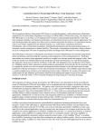
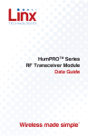
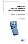
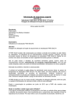
1
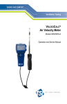
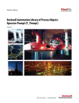
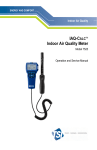
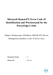
Exposure Monitoring Model 8522 RESPICON Particle Sampler TM Operation and Service Manual 1980320, Revision E August 2007 Model 8522 RESPICON™ Particle Sampler Operation and Service Manual August 2007 P/N 1980320, Rev. E SHIP TO/MAIL TO: TSI Incorporated 500 Cardigan Road Shoreview, MN 55126-3996 USA U.S. Sales and Customer Service: (800) 874-2811/(651) 490-2811 Fax: (651) 490-3824 E-mail address: [email protected] Website: http://www.tsi.com INTERNATIONAL Sales and Customer Service: (001 651) 490-2811 Fax: (001 651) 490-3824 Copyright © TSI Incorporated / 1997–2007 / All rights reserved. Address TSI Incorporated / 500 Cardigan Road / Shoreview, MN 55126 / USA Fax No. (651) 490-3824 LIMITATION OF WARRANTY AND LIABILITY (effective July 2000) Seller warrants the goods sold hereunder, under normal use and service as described in the operator's manual, shall be free from defects in workmanship and material for twenty-four (24) months, or the length of time specified in the operator's manual, from the date of shipment to the customer. This warranty period is inclusive of any statutory warranty. This limited warranty is subject to the following exclusions: a. Hot-wire or hot-film sensors used with research anemometers, and certain other components when indicated in specifications, are warranted for 90 days from the date of shipment. b. Parts repaired or replaced as a result of repair services are warranted to be free from defects in workmanship and material, under normal use, for 90 days from the date of shipment. c. Seller does not provide any warranty on finished goods manufactured by others or on any fuses, batteries or other consumable materials. Only the original manufacturer's warranty applies. d. Unless specifically authorized in a separate writing by Seller, Seller makes no warranty with respect to, and shall have no liability in connection with, goods which are incorporated into other products or equipment, or which are modified by any person other than Seller. The foregoing is IN LIEU OF all other warranties and is subject to the LIMITATIONS stated herein. NO OTHER EXPRESS OR IMPLIED WARRANTY OF FITNESS FOR PARTICULAR PURPOSE OR MERCHANTABILITY IS MADE. TO THE EXTENT PERMITTED BY LAW, THE EXCLUSIVE REMEDY OF THE USER OR BUYER, AND THE LIMIT OF SELLER'S LIABILITY FOR ANY AND ALL LOSSES, INJURIES, OR DAMAGES CONCERNING THE GOODS (INCLUDING CLAIMS BASED ON CONTRACT, NEGLIGENCE, TORT, STRICT LIABILITY OR OTHERWISE) SHALL BE THE RETURN OF GOODS TO SELLER AND THE REFUND OF THE PURCHASE PRICE, OR, AT THE OPTION OF SELLER, THE REPAIR OR REPLACEMENT OF THE GOODS. IN NO EVENT SHALL SELLER BE LIABLE FOR ANY SPECIAL, CONSEQUENTIAL OR INCIDENTAL DAMAGES. SELLER SHALL NOT BE RESPONSIBLE FOR INSTALLATION, DISMANTLING OR REINSTALLATION COSTS OR CHARGES. No Action, regardless of form, may be brought against Seller more than 12 months after a cause of action has accrued. The goods returned under warranty to Seller's factory shall be at Buyer's risk of loss, and will be returned, if at all, at Seller's risk of loss. Buyer and all users are deemed to have accepted this LIMITATION OF WARRANTY AND LIABILITY, which contains the complete and exclusive limited warranty of Seller. This LIMITATION OF WARRANTY AND LIABILITY may not be amended, modified or its terms waived, except by writing signed by an Officer of Seller. Service Policy Knowing that inoperative or defective instruments are as detrimental to TSI as they are to our customers, our service policy is designed to give prompt attention to any problems. If any malfunction is discovered, please contact your nearest sales office or representative, or call TSI's Customer Service department at (800) 874-2811 (USA) or (001 651) 490-2811 (International). Trademarks RESPICON is a trademark of TSI Incorporated. CONTENTS SAFETY INFORMATION ..................................................................III CHAPTER 1 UNPACKING AND PARTS IDENTIFICATION ...........1 Unpacking the RESPICON Particle Sampler..................................1 Parts Identification For the RESPICON Particle Sampler...............2 Optional Accessories/Replacement Parts....................................6 Required Accessories (not sold by TSI).......................................6 CHAPTER 2 SETTING-UP: PREPARATION FOR SAMPLING ......7 Overview.......................................................................................7 Disassembling the RESPICON Particle Sampler ...........................7 Preparing the Filters .....................................................................8 Removing Old Filters .............................................................8 Cleaning the Nozzles.............................................................9 Preparing New Filters ............................................................9 Loading Filters into Filter Holders ........................................10 Assembling the RESPICON Particle Sampler ..............................11 Supplying Flow to the RESPICON Particle Sampler ....................13 Checking the Total Flow.............................................................13 CHAPTER 3 OPERATION ..............................................................15 Overview.....................................................................................15 Caution Against Operating the RESPICON Particle Sampler Without Filters .........................................................................15 Using the RESPICON Particle Sampler for Personal Aerosol Sampling .................................................................................15 Using the RESPICON Particle Sampler for Area Aerosol Sampling .................................................................................16 Unloading the RESPICON After a Sample ...................................16 Weighing the Filters....................................................................16 Recording the Data ....................................................................16 CHAPTER 4 MAINTENANCE.........................................................17 Overview.....................................................................................17 Maintenance Schedule...............................................................17 Before Each Use ........................................................................17 Check O-rings ............................................................................17 Clean Impactor Nozzles .............................................................18 Perform Total Flow Check..........................................................19 Perform Stage Flow Check ........................................................20 Clean Filter Stages, Body Unit, Inlet Head.................................22 Clean Orifices .............................................................................22 Replace O-rings .........................................................................23 i Replace Orifices ........................................................................ 23 CHAPTER 5 DATA ANALYSIS ..................................................... 25 Overview.................................................................................... 25 Using the Data Analysis Form ................................................... 25 Setting up the Electronic Data Analysis Form .................... 25 Using the Electronic Data Evaluation Form ........................ 25 Creating a Hard copy Data Analysis Form ......................... 26 Formulas.................................................................................... 26 Respirable Fraction ............................................................. 26 Thoracic Fraction ................................................................ 26 Inhalable Fraction................................................................ 26 Extra-thoracic Fraction ........................................................ 27 Tracheo-bronchial Fraction ................................................. 27 CHAPTER 6 TROUBLESHOOTING .............................................. 29 APPENDIX A SPECIFICATIONS................................................... 31 AVAILABLE APPLICATION NOTES • RESPICON, Model 8522 Frequently Asked Questions........................................ ITI-049 • Health-Based Particle Size-Selective Sampling ...................................................................... ITI-050 • How a Virtual Impactor Works .................................... ITI-057 To obtain any of the listed Application Notes, contact TSI at: U.S. (800) 874-2811/(651) 490-2811, Fax: (651) 490-3824 International (001 651) 490-2811, Fax: (001 651) 490-3824 These Application Notes can also be found under TSI’s web site: http://www.tsi.com. ii SAFETY INFORMATION There are no special safety concerns involved with the use and operation of the RESPICON™ Particle Sampler. The RESPICON Particle Sampler is a mechanical device, with no electronics or moving parts. iii iv Chapter 1 Unpacking and Parts Identification Unpacking the RESPICON Particle Sampler Carefully unpack the Model 8522 RESPICONTM Particle Sampler and accessories from the carrying case. Use the tables and illustrations below to make certain that there are no missing components. Contact TSI immediately if anything is missing or damaged. Figure 1-1: Model 8522 RESPICON Particle Sampler Quantity Item Description 1 RESPICON Particle Sampler (with removal cylinder and disk) 1 Carrying Case 1 Stage Flow Checker 1 Total Flow Checker 1 Filter forceps 1 pkg (12) Filter holders 1 Sample tube (4 ft) 1 pkg (25) Pipe cleaners 1 Data Analysis Spreadsheet (Microsoft® Excel) 1 Model 8522 RESPICON Operation and Service Manual 1 Certificate of Conformance Part/Model 801132 801143 801133 801134 801142 801137 801138 801147 1082624 1980320 ® Microsoft is a registered trademark of Microsoft Corporation. 1 Parts Identification For the RESPICON Particle Sampler Figures 1-2 through 1-6 identify the parts of the Model 8522 RESPICON Particle Sampler. Please become familiar with these components before proceeding. 1 3 2 Figure 1-2 Model 8522 RESPICON Particle Sampler 1. RESPICON sampler 2. Removal disk 2 3. Removal cylinder Chapter 1 2 1 5 3 4 Figure 1-3 Parts Explosion: RESPICON Particle Sampler 1. RESPICON body unit 2. Inlet head 3. Stage #1 Unpacking and Parts Identification 4. Stage #2 5. Stage #3 3 1 3 2 Figure 1-4: Flow Checking Equipment 1. Stage flow checker 2. Stage flow checker inlet 4 3. Total flow checker Chapter 1 1 Figure 1-5: RESPICON Filters and Holder 1. Filter holder (shown disassembled) with covers (x2) 3 1 2 Figure 1-6: Miscellaneous Accessories 1. 2. Sample tube Filter forceps Unpacking and Parts Identification 3. Pipe cleaners 5 Optional Accessories/ Replacement Parts The following items are sold by TSI as optional accessories or replacement parts. They are not included with the standard Model 8522 RESPICON Particle Sampler. Figure 1-7: Optional Accessories Quantity Item Description 1 pkg O-ring kit (contains 10: 42 x 1.5mm, 10: 32 x 1.5 mm, 5: 6 x 1mm) 1 pkg Orifice kit (3 qty) 1 Rotameter kit (contains high flow and low flow rotameters, with bases) 1 RESPICON chest harness 1 Inlet head, 2.5 μm cut Part/Model 801141 801146 8522-01 8522-02 8522-03 Required Accessories (not sold by TSI) The following items are necessary in order to operate the RESPICON Particle Sampler. They are not included with the standard Model 8522 nor are they available for sale from TSI. Customers who purchase the RESPICON quite often already own such items and may use them when operating the RESPICON. This chart contains specification information only. Figure 1-8: Required Accessories Quantity Item Description 1 Personal sampling pump Minimum flow rate: 3.5 Lpm Pressure drop rating: 18 in. WC (4.5 kPa) @ 3.11 Lpm Battery power for at least 8 hours of operation at above flow and pressure drop Automatic shutoff after preset sampling time 1 Primary flow calibration system Bubble flow meter (or equivalent) Minimum range of 0.1 to 3.5 Lpm 3/sample 37-mm filters (type of filter media is dependent on sample criteria and associated analytical method to be used). The RESPICON requires two of the 37-mm filters to have a 4-mm central hole; the third 37-mm filter does not have a central hole. These filters should be obtained from an accredited industrial hygiene laboratory. Filters cannot be obtained through TSI. 6 Chapter 1 Chapter 2 Setting-Up: Preparation for Sampling Overview The Model 8522 RESPICONTM Particle Sampler is a size-selective gravimetric sampler. It is used to determine personal or area aerosol exposure based upon the mass loading of particles on three sampling filters. The total flow through the RESPICON Particle Sampler and the internal flows within the RESPICON Particle Sampler are critical variables to ensure proper functioning of the device. Before operating the RESPICON Particle Sampler, it is necessary to 1) prepare the filters and 2) verify the flowrates. Disassembling the RESPICON Particle Sampler To disassemble the RESPICON Particle Sampler, first remove the inlet head by pressing down slightly and turning counter-clockwise. Place the body unit on the removal cylinder and cover with the removal disk. See Figure 2-1 below. Figure 2-1: Place Body Unit on Removal Cylinder. Cover with Removal Disk. 7 Press down with the palm of your hand on the removal disk. The filter stages will come loose and the body can be pushed down. Figure 2-2: Press Down to Remove Filter Stages Preparing the Filters Removing Old Filters Remove the three filter stages from the body unit and remove the filter holder from each stage. If appropriate, place the top and bottom cover on each filter holder and save for later analysis. Otherwise, remove and discard the old filters. Note: The filter stages are identified by ring(s) inscribed around the perimeter. Filter stage #1 has one ring, filter stage #2 has two rings, etc. The filter stages must be assembled in order, with #1 on the top and #3 on the bottom. See Figure 2-3 below. 8 Chapter 2 Figure 2-3: Filter Stage #1 with Filter Holder Note: Inscribed single ring denoting Stage #1 Cleaning the Nozzles The impactor nozzles must be cleaned before each use. See Chapter 4, "Clean Impactor Nozzles" for more information. Preparing New Filters Prepare three 37-mm filters—two containing a central hole and one without a hole. Note: The RESPICON Particle Sampler requires two of the 37-mm filters to have a 4-mm central hole. These filters can be obtained through an accredited industrial hygiene laboratory. In addition, the RESPICON Particle Sampler requires filters with a specified pressure drop and filtration efficiency. Failure to use a recommended style of filter may result in improper functioning of the RESPICON Particle Sampler and inaccurate gravimetric results. Pre-condition the filters and weigh them on an approved microbalance. TSI recommends using a scale with micro-gram resolution (not just milligram) to help measure extremely small particle mass. ! Caution Use the supplied conductive forceps for handling the filters at all times. Set-up: Preparation for Sampling 9 Record the pre-weights on a data sheet or on the Data Analysis Spreadsheet (supplied with the RESPICON Particle Sampler). Note: Follow standard gravimetric sampling conventions for preconditioning, weighing, labeling and handling of the filters. A description of such procedures is beyond the scope of this manual. Please see “Air Sampling Instruments” by the ACGIH 1 or other industrial hygiene reference texts for a complete description of gravimetric filter preparation. Loading Filters into Filter Holders With the top ring removed, place the first 37-mm filter with hole into the filter holder base. Before replacing the top ring, place the filter holder base into filter stage #1. Gently tap the side of the filter stage to allow the filter to center itself on the impactor nozzle located in the center of the stage. See Figure 2-4 below. Figure 2-4: Tap Side of Filter Stage to Center Filter Over Nozzle Align the top ring and gently press into place, using both hands. Repeat this process for the second filter and filter stage #2. Load the remaining filter (without hole) into a filter holder and place into filter stage #3. 1 Air Sampling Instruments, 1995, published by the American Conference of Governmental Industrial Hygienists, Inc., 1330 Kemper Meadow Drive, Cincinnati, Ohio 45240-1634 10 Chapter 2 Assembling the RESPICON Particle Sampler Stack the assembled filter stages with stage #1 on the top and stage #3 on the bottom. Examine the exterior of the filter stages to ensure that the two Orings on each stage are intact. Note: If the stages are inadvertently assembled in the incorrect order, they will not physically fit into the body unit. Do not force the units if you experience excessive resistance. Place the body unit over the removal cylinder. Place the stacked filter stages onto the removal cylinder and lift the body unit. See Figures 2-5 through 2-6 below. Figure 2-5: Place Body Unit Over Removal Cylinder. Place Stacked Filter Stages into Body Unit. Set-up: Preparation for Sampling 11 Figure 2-6: Lift Body Unit to Cover Filter Stages Invert the removal cylinder. Using the removal cylinder, press firmly down on the top of the filter stage stack until the three stages are seated tightly at the bottom of the body unit. See Figure 2-7 below. Figure 2-7: Press Down to Seat Filter Stages Into Body Unit 12 Chapter 2 Note: This step requires a fair amount of force to overcome the friction caused by the O-rings. Do not press filter stages into body unit using fingers. Doing so may disrupt or damage the fragile filters. ! Caution Do not use grease on the O-rings (see Chapter 4, "Checking O-rings," for more information. Do not install the inlet head until after performing the total flow check. Supplying Flow to the RESPICON Particle Sampler The Model 8522 RESPICON Particle Sampler must be operated in conjunction with a suitable personal sampling pump (see Figure 1-7 for specifications). Since the RESPICON Particle Sampler has a significant amount of internal flow resistance, it is important to carefully choose a pump which can provide the required flow throughout the entire sampling interval. Connect the outlet port (located on the side of the body unit) of the RESPICON to the inlet port on the sampling pump, using the supplied sample tubing. Checking the Total Flow Attach the total flow checker by placing onto the body unit and turning clock-wise. Attach a tube from the total flow checker to a suitable flowmeter. Adjust the sample pump to 3.11 Lpm. Verify that the flow rate is correct and make adjustments to the pump as needed. See Chapter 4, "Perform Total Flow Check" for more information. Note: The filters to be used during the test must be installed in the RESPICON when setting the total flow rate. Remove the total flow checker from the body unit. Place the inlet head onto the body unit and tighten by turning clock-wise. The RESPICON Particle Sampler is now ready for sampling. Note: Proper operation of the RESPICON Particle Sampler depends upon correct total flow and three correct internal flows. Because of the inherent variability of sampling pumps, it is important for you to verify correct total flow through the instrument using either a primary flow standard (bubble flow meter, or equivalent) or a secondary flow standard (rotameter or equivalent). This must be done before each use of the RESPICON Particle Sampler. Set-up: Preparation for Sampling 13 The three internal flows within the RESPICON Particle Sampler should also be verified on a less frequent basis (depending upon usage). This step requires the use of the stage flow checker supplied with the RESPICON Particle Sampler. See Chapter 4, "Perform Stage Flow Check," for more information. 14 Chapter 2 Chapter 3 Operation Overview Although the RESPICONTM Particle Sampler gives much more useful information than the typical gravimetric sampler, it is still subject to many of the same constraints as other samplers. To obtain useful information, the RESPICON Particle Sampler must be used in the context of a well-designed sampling strategy. It is well beyond the scope of this manual to review all of the considerations which go into an air sampling strategy. You are encouraged to reference standard textbooks on the subject, such as Air Sampling Instruments 1, published by the ACGIH. The following sections detail some concerns which are particular to the RESPICON Particle Sampler. Caution Against Operating the RESPICON Particle Sampler Without Filters The RESPICON Particle Sampler is designed to only be operated with the sampling filters in place. Care should be taken to avoid operating the unit for extended periods of time without these filters. If the filters are not installed, there is the possibility of accumulating particles in areas of the unit which are difficult to clean, such as the porous backup plates and the flow-control orifices. This would then affect the performance of the sampler. Using the RESPICON Particle Sampler for Personal Aerosol Sampling The RESPICON Particle Sampler was designed primarily as a personal aerosol sampler for occupational exposure assessment. During operation, it should be mounted in the breathing zone. The body of the RESPICON Particle Sampler contains a belt clip which can be used to attach it to an article of clothing or an optional harness. Note: The RESPICON Particle Sampler should not be worn on a waist belt, as this would be outside of the breathing zone. TSI sells an accessory chest harness which is designed to comfortably hold the RESPICON Particle Sampler close to the body, within the breathing zone (see Chapter 1 for more information). 1 Air Sampling Instruments, 1995, published by the American Conference of Governmental Industrial Hygienists, Inc., 1330 Kemper Meadow Drive, Cincinnati, Ohio 45240-1634 15 Using the RESPICON Particle Sampler for Area Aerosol Sampling The RESPICON Particle Sampler may also be used as an area sampler. The bottom of the RESPICON Particle Sampler contains a universal tripod thread. This allows the RESPICON Particle Sampler to be mounted to a standard tripod and placed in the area of interest. The RESPICON Particle Sampler may also be placed on a flat surface for area sampling. You should carefully consider factors within the sampling area which might affect an integrated area sample, such as: • • • • Air currents (from blowers, exhaust fans, wind, etc.) Local sources of aerosol (grinding, welding, etc.) Activity patterns Mounting height and location Unloading the RESPICON After a Sample To remove the filters, follow the procedure outlined in Chapter 2, "Disassembling the RESPICON." Special care must be taken to avoid damaging the filters or disrupting any of the accumulated aerosol. The filter holders are supplied with top and bottom covers which must be used when transporting the samples for analysis. Weighing the Filters To determine the mass concentration of each of the size fractions, the three RESPICON Particle Sampler filters must be post-weighed on a micro-balance. It is good practice to use the same balance as was used to pre-weigh the filters. The filters should be pre-conditioned in the same manner as they were for pre-weighing. After weighing, the filters may be analyzed further using microscopic or chemical analysis (depending upon the targeted substance and filter type). Recording the Data Record the post-weights and duration of sample on the data sheet or spreadsheet. TSI recommends the use of the supplied Microsoft® Excel spreadsheet, which automatically calculates the mass concentration of each size fraction. A complete overview of data analysis is found in Chapter 5. 16 Chapter 3 Chapter 4 Maintenance Overview The RESPICONTM Particle Sampler is a very low maintenance instrument. It contains no electronics or moving parts. Maintenance consists almost entirely of cleaning the instrument and checking flow rates. Maintenance Schedule The maintenance schedule for the RESPICON Particle Sampler is largely determined by usage patterns. If the instrument is used in very dusty, dirty conditions, it will obviously require more frequent cleaning than if used in relatively clean conditions. The table below summarizes the recommended procedures and frequency. Figure 4-1: Recommended Maintenance Item Frequency Before Each Use Check O-rings Clean impactor nozzles (x2) Perform total flow check Every Fifth Use Perform stage flow check Non-Routine Clean orifices Clean filter stages, body unit Clean inlet head Replace O-rings Replace orifices Before each use Before each use Before each use Every fifth use (more often for dirty conditions) Quarterly, or if unable to obtain correct flow on each stage As needed As needed Only if damaged Only if damaged Check O-rings The RESPICON Particle Sampler contains 13 O-rings; each one of them is important for maintaining good seals and correct flow rates within the instrument. You should become familiar with the location of each O-ring and should routinely inspect them prior to assembly of the instrument. The following list details the size and location of each O-ring. It also identifies 17 those O-rings which need special attention, due to their importance or special conditions. Figure 4-2: List of O-rings Location Diameter Perimeter of inlet head 42-mm Underside of inlet head; underside of 1st and 2nd filter stage (x3) Top of each filter stage (x3) Perimeter of each filter stage (x6) 32-mm Special Concerns Subject to frequent twisting; may distort or tear May become dislodged 32-mm 42-mm N/A N/A Note: Do not use grease or other lubricant on the O-rings, as this may cause the flow orifices to plug. Clean Impactor Nozzles Aerosol flow through the virtual impactor nozzles is critical to the proper functioning of the RESPICON Particle Sampler. These nozzles should be cleaned before each sample using the supplied pipe cleaners and/or dry compressed air. The nozzles are located at (see Figure 4-3): • • • The underside of the inlet head The center of the first filter stage The center of the second filter stage. Inlet Head Stage #1 Figure 4-3: Virtual Impactor Nozzle Locations 18 Chapter 4 Perform Total Flow Check The total flow through the RESPICON Particle Sampler must be maintained at 3.11 Lpm ±2% (3.04 to 3.17 Lpm). A check of the total flow is a good way to verify the system integrity of the RESPICON Particle Sampler. This quick test helps to verify that: • • • All O-rings are in place and intact Filters are correctly installed The pump flow is correctly set. To perform a total flow check, use the following procedure: 1. Prepare the RESPICON Particle Sampler for sampling, by cleaning it and installing the three filters and filter stages. 2. Remove the inlet head and install the total flow checker. 3. Attach a tube from the total flow checker to a flow measuring instrument with a capacity of at least 3.2 Lpm (rotameter or other). 4. Attach the sample tube from the RESPICON Particle Sampler outlet to the sample pump (see Figure 4-4). 5. Turn on the pump and adjust to 3.04-3.17 Lpm. Notes: This step is also a useful way to calibrate the internal flowmeter (rotameter or other) on the personal sampling pump. A built-in rotameter on a pump can be quite inaccurate, especially in this case where a high-pressure drop device is installed on the inlet. The use of a secondary rotameter (or other flowmeter) upstream of the RESPICON Particle Sampler provides a more accurate indication of flow. Do not operate the RESPICON Particle Sampler for an extended period of time without the filters installed. This may cause particles to become trapped in the flow orifices or the porous plastic at the base of each filter stage. Maintenance 19 Figure 4-4: Attach Flowmeter and Sampling Pump to RESPICON Total Flow Checker 1 Perform Stage Flow Check While the total flow through the RESPICON Particle Sampler is a good test of system integrity, it does not tell the whole story. It is possible for the total flow to be correct while the three internal flows are out of balance. These flows regulate the functioning of the two virtual impactors and maintain the correct aerosol size separation. To perform a check of the individual stage flows, use the following procedure: Note: When performing the Stage Flow Check, it is essential to recheck the total flow with the filters removed and the stage flow checker installed, before checking the individual flows. Please carefully follow the directions step-by-step. 1. Remove the filters and filter stages (if they are installed in the body unit). 2. Install the stage flow checker into the body unit (make sure it is seated against the bottom of the body unit). 3. Install the total flow checker onto the top of the body unit (make sure it is seated correctly, and the O-ring makes a good seal). 1 The display of any particular brand of pump or flowmeter does not imply endorsement by TSI Inc. 20 Chapter 4 4. Attach the pump to the RESPICON Particle Sampler outlet and a suitable flowmeter to the total flow checker inlet (see Figure 4-4). 5. Turn on the pump and adjust to a nominal value of 3.11 Lpm (3.04–3.17 Lpm). Note: For greatest accuracy, it is important to leave the pump running, with the flow setting undisturbed, until completion of the stage flow checks. 6. Remove the total flow checker. 7. Install the stage flow checker inlet into the hole marked "Q1." Note: For ease of insertion, slightly moisten the inlet fitting O-rings with water (no grease), and insert the fitting with a twisting motion. 8. Attach a tube from the stage flow checker inlet to the flow measuring instrument (rotameter, bubble flow meter). See Figure 4-5. 9. With the pump still running, check the flowmeter reading. Figure 4-6 contains the desired flow rate for each stage. 10. Repeat for flow measuring steps for Q2 and Q3. Figure 4-5: Attach Flowmeter and Sampling Pump to RESPICON Stage Flow Checker Maintenance 21 Figure 4-6: Flow Rate for Three Stages Stage Nominal Accuracy Qtotal 3.11 Lpm ±2% Q1 2.66 Lpm ±3% Q2 0.333 Lpm ±5% Q3 0.111 Lpm ±5% Range 3.04 – 3.17 Lpm 2.59 – 2.75 Lpm 0.31 – 0.35 Lpm 0.105 – 0.116 Lpm Clean Filter Stages, Body Unit, Inlet Head Most of the aerosol entering the RESPICON Particle Sampler is captured on the filters. However, after repeated use, some build-up may occur within the body of the RESPICON Particle Sampler and on the filter stages. These areas are easily cleaned with a damp cloth or compressed air. Because of its construction, the inlet head may be difficult to clean (it should not be disassembled for cleaning). Soak the inlet head in a soapy solution; rinse and dry before re-installing. Clean Orifices The three orifices, located near the RESPICON Particle Sampler outlet, control the internal flows within the instrument. After prolonged use, the orifices may need to be cleaned. If you are not able to obtain the correct flows within the RESPICON (when the total flow is correct) it is also a possible indication that the orifices need to be cleaned. To clean the orifices, use the following procedure: Note: The three orifices contain a color-coded dot. The body unit has a matching color dot to help the user reassemble the orifices in the correct location. 1. Using a small, slotted screwdriver, remove the three orifices located next to the RESPICON Particle Sampler outlet (see Figure 4-7). 2. Blow out any accumulated particles using compressed air. 3. The orifices may also be cleaned ultrasonically or with a mild soap solution. Rinse and dry before re-installing. 4. Install the red, color-coded orifice at the top (2.66 Lpm); install the yellow orifice in the middle and the green orifice at the bottom. ! 22 Caution Do not use a needle or broach to clean the inside of the orifice. This may permanently damage the precision hole and seriously affect the functioning of the RESPICON. Chapter 4 Orifice #1 Figure 4-7: Orifice Location, Orifice #1 Shown Removed Replace O-rings The O-rings should not need replacement under normal operating conditions. If an O-ring is pinched, damaged or lost, it must be replaced immediately. Note: Do not use greases or lubricants on the O-rings, as this may cause the orifices to plug up. Replace Orifices Under normal operating conditions, the orifices will never need replacement. If the orifices are inadvertently damaged or lost, a replacement kit is available. See Chapter 1 for more information. Maintenance 23 24 Chapter 4 Chapter 5 Data Analysis Overview The Model 8522 RESPICONTM Particle Sampler provides the raw data necessary to calculate the three aerosol size fractions: inhalable, thoracic, and respirable. The mass concentrations of the these three fractions can be calculated using the following values: • The individual aerosol masses deposited upon the filters: m1, m2 and m3 (milligrams) • The sampling duration: ts (minutes) • The volumetric flow rates: Q1, Q2 and Q3 (Lpm) Collection of the raw data was covered in the sections "Weighing the Filters" and "Recording the Data" in Chapter 3. This chapter will outline the simple calculations required to convert the raw mass data into sizefractionated concentrations. Using the Data Analysis Form The RESPICON Particle Sampler is supplied with an electronic Data Analysis Form (Microsoft® Excel formatted spreadsheet). This form is used to both gather and analyze the raw data from the RESPICON Particle Sampler. The electronic file is an Excel vs. 5.0 file. Please note the following when using this spreadsheet: Setting up the Electronic Data Analysis Form • Launch your spreadsheet program (Excel, Lotus, etc.). • Open the file "respdata.xls" found on the supplied 3½” diskette. • Save the file into your user directory. Your operating system (Win 3.11, Win 95, etc.) may request that you update the file while saving, depending upon the software brand and version which you are running. • Using the "save-as" command, create a backup version of the file, using an appropriate filename. Using the Electronic Data Evaluation Form • Launch your spreadsheet program (Excel, Lotus, etc.). • Open the file "respdata.xls" from your user directory. 25 Note: • The actual file may have a different file extension, depending upon which software you are running. If you intend to permanently record the test data from a particular test in electronic format, use the "save-as" command to create a new file, with a unique name. This new file will be used to gather, analyze and permanently record the test data. Do not use the "save" command to overwrite the original file. • Fill out the data portions of the form; the spreadsheet will automatically calculate the size fractions/concentrations. The following fields must be filled in: 1. Duration of sample 2. Pre-weights: filters 1,2 & 3 3. Post-weights: filters 1,2 & 3 • Use the "tab" key to move among the user-editable fields on the form (name, date, location, etc.). • Non-editable, formula cells, are locked and cannot be changed. Creating a Hard copy Data Analysis Form • It may be useful to create a blank, printed copy of the Data Analysis Form, for use in data gathering. • Simply print out the blank spreadsheet form. The formulas used to calculate each cell are included on the form to allow for manual calculations. Formulas The following table contains the terms and formulas used to calculate the aerosol size fractions. Respirable Fraction Cresp = ( m1) *1000 ( Q1)*ts Thoracic Fraction Cthor = ( m1+m2 ) *1000 ( Q1+Q2)*ts Inhalable Fraction 1+ m 2 + m 3 ) *1000 Cinh = (m ⎛⎜ Q1+ Q 2 + Q 3 ⎞⎟*ts ⎝ ⎠ 26 Chapter 5 The following definitions are used: Respirable fraction; mg/m3 Cresp Thoracic fraction Cthor Inhalable fraction Cinh Extra-thoracic fraction Cexth Tracheo-bronchial fraction Ctb Mass deposited on filter #1; mg m1 Mass deposited on filter #2 m2 Mass deposited on filter #3 m3 Flow rate through filter #1 (2.66 Lpm) Q1 Flow rate through filter #2 (0.33 Lpm) Q2 Flow rate through filter #3 (0.11 Lpm) Q3 Sample duration; minutes ts Once the three basic size fractions are calculated, it is to determine the intermediate size fractions using the following simple formulas: Extra-thoracic Fraction The extra-thoracic fraction are the coarse particles which are inhaled but do not penetrate to the larynx. The extra-thoracic fraction is obtained by subtracting the thoracic fraction from the inhalable. Cexth = Cinh - Cthor Tracheo-bronchial Fraction The tracheo-bronchial fraction are the intermediate-sized particles which penetrate beyond the larynx but do not reach the alveoli. The tracheo-bronchial fraction is obtained by subtracting the respirable fraction from the thoracic fraction. Ctb Data Analysis = Cthor − Cresp 27 28 Chapter 5 Chapter 6 Troubleshooting The table below list the symptoms, possible causes and recommended solutions for common problems encountered with the RESPICONTM Particle Sampler. Symptom When using total flow checker or stage flow checker, flow rates are incorrect. Possible Cause Leak. Corrective Action Check connections for leaks. Make sure tubing is correct size and tightly fitting. Check O-rings. Make sure all O-rings are properly installed; not twisted or torn. Tighten adapter (turn clockwise). Dirty impactor nozzle. Clean virtual impactor orifices using pipe cleaner or compressed air. See Chapter 4 "Clean Impactor Nozzles." Dirty orifice(s). Remove orifice(s). Clean with compressed air or mild soap solution. Blow dry with clean compressed air. DO NOT INSERT OBJECT INTO ORIFICE! Re-install. Pump setting is incorrect. Using the total flow checker, set pump flow rate to 3.11 Lpm (see Chapter 4 "Perform Total Flow Check). Once total flow is correct, verify individual flows (see Chapter 4 "Perform Stage Flow Check"). 29 Symptom Incorrect flow rate (continued). Possible Cause Pump not able to maintain proper flow rate. Corrective Action Verify operating parameters on pump; make sure pump is rated for this application. Make sure batteries are fully charged (or operate with AC adapter). There is no measurable deposit on the first filter stage (respirable fraction). Flow checking components are connected incorrectly. See Figures 4-4 and 4-5. Verify that rotameter, RESPICON, flow checker and sampling pump are connected in correct manner. Wrong filters installed (filters may have too high pressure drop). Use only TSI approved filters in RESPICON. Improper scale used for weighing filter. Use scale with micro-gram resolution (scale with milligram resolution may not be adequate to measure small amounts of particles). Sample period was too short; insufficient particles deposited upon filter. Sample for longer period of time (preferably 8-hour minimum). No solution. Air contains very low concentrations of aerosol. 30 Chapter 6 Appendix A Specifications Specifications are subject to change without notice. SENSITIVITY: Instrument type: Two stage, virtual impactor, with three stage gravimetric filter sampler 50% cut size: (aerodynamic dia.) Inlet: 100 micron Stage 1: 4 micron Stage 2: 10 micron Stage 3: all remaining particles INSTRUMENT TEMPERATURE RANGE: Operating range: The RESPICON has no temperature limitations. Please verify operating limits for the personal sampling pump. PHYSICAL: Filter type: 37-mm diameter filters (2 each: with central hole; 1 each without hole) External dimensions: 3.22 in. x 2.75 in. x 2.0 in. (HWD) (82 mm x 70 mm x 50 mm) Weight: 0.64 pounds (290 grams) Tripod mount: ¼-20 threaded hole Pressure drop: 16 inches H2O (4 kPa) REQUIRED ACCESSORIES: Personal Sampling Pump: Minimum flow rate: 3.5 Lpm Pressure drop rating: 18 in. WC (4.5 kPa) @ 3.11 Lpm Battery power for at least 8 hours of operation at above listed flow and pressure drop Automatic shutoff after preset sampling time 31 REQUIRED ACCESSORIES (continued): Primary flow calibration system Bubble flow meter (or equivalent) Minimum range of 0.1 to 3.5 Lpm 37-mm filters (type of filter media is dependent on sample criteria and associated analytical method to be used) The RESPICON requires two of the 37-mm filters to have a 4-mm central hole; the third 37-mm filter does not have a central hole. These filters should be obtained from an accredited industrial hygiene laboratory. Filters cannot be obtained through TSI. 32 Appendix A TSI Incorporated – 500 Cardigan Road, Shoreview, MN 55126 U.S.A USA Tel: +1 800 874 2811 E-mail: [email protected] Website: www.tsi.com UK Tel: +44 149 4 459200 E-mail: [email protected] Website: www.tsiinc.co.uk France Tel: +33 491 95 21 90 E-mail: [email protected] Website: www.tsiinc.fr Germany Tel: +49 241 523030 E-mail: [email protected] Website: www.tsiinc.de Sweden Tel: +46 8 595 13230 E-mail: [email protected] Website: www.tsi.se India Tel: +91 80 41132470 E-mail: [email protected] China Tel: +86 10 8260 1595 E-mail: [email protected] Contact your local TSI Distributor or visit our website www.tsi.com for more detailed specifications. P/N 1980320 Rev E Copyright © 2007 by TSI Incorporated Printed in U.S.A.