1
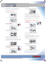
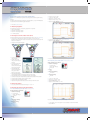
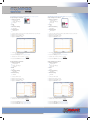
Technical Service Manual XM400-30A04 v2.0 Contents Page 1. Performance test for the StimPod NMS410/450 2 1.1) Performance tests at the site of use 2 1.1.1) Nerve Locating Mode 2 1.1.2) Combined Nerve Mapping/Nerve Locating Mode 2 1.1.3) Neuromuscular Blocking Agent Mode (NMBA Mode)(NMS450 only) 2 2. Test instructions for the safety checks (STK) 3 2.1) Measuring Equipment 3 2.2) Checking the external condition of the device 3 2.3) Performance Testing 3 2.4) Checking and measuring the Stimpod Output; 3 2.4.1) Pulse Width test (Locate mode, Locating cable) 3 2.4.2) Frequency test (Locate mode, insert Locating cable) 3 2.4.3) Stimulus current test (Locate Mode, Insert Locating cable) 4 2.4.4) Stimulus current test (Locate Mode, Insert Map/Locating cable) 4 2.4.5) Stimulus current test (Mapping Mode, Insert Map/Locating cable) 5 2.4.6) Stimulus current test (NMBA Mode, Insert NMBA cable) 5 2.4.7) Default Settings 6 3. Replacing the electrode cable 6 4. Repair address 6 Appendix: Report Template Manufacturer Xavant Technology PTY (LTD) 169 Garstfontein Road Ashlea Gardens, 0081 Pretoria, South Africa Tel: +27 (0) 12 755 9491 Fax: +27 (0) 12 346 7271 E-Mail: [email protected] Web: www.xavant.com Legal Representative in the EU Emergo Group 15 Molenstraat, 2513 BH, The Hague The Netherlands Tel: +31 70 345 8570 Fax: +31 70 346 7299 1. Performance test for the StimPod NMS410/450 Before operating and using the device a performance test must be carried out at the site of use in compliance with § 5 MPBetreibV. • Short-circuit the Nerve Mapping probe and the ECG connector. The following screen should appear on the display. 1.1 Performance tests at the site of use • Insert the batteries and switch on the device. The following screen should appear on the display. followed by • The LED should flash GREEN and if sound is enabled in the menu a beep should be heard each time a stimulus is delivered. • Stimulus should occur at the set frequency, (1,2 or 5 Hz). • Use the adjusting wheel and slowly increase the current to 20mA. • Monitor that the stimulating waveform, measured and displayed in the diagnostic window is square and that the top part of the square wave touches the dotted line, which represents the current setting. In order to test the Nerve Locating connection and device functionality follow the instructions in 1.1.1. 1.1.3. Neuromuscular Blocking Agent Mode (NMBA Mode) (NMS450 only) 1.1.1. Nerve Locating Mode • Insert the NMBA Cable. The following screen should appear on the display. y. • Insert the Nerve Locating Cable. The following screen should appear on the display. y. • Ensure that the device is in ‘TOF’ mode. • Short-circuit the red and black electrode connectors. • The LED should flash RED and no audible feedback should be heard. • Short-circiut the needle connector and the ECG connector. The following screen should appear on the display. • Use the adjusting wheel and increase the current to 80mA. • Press the ‘play/pause’ button while shaking the accelerometer. • The LED should flash GREEN and if sound is enabled in the menu a beep should be heard each time a stimulus is delivered. • Stimulus should occur at the set frequency. (1,2 or 5Hz). • Use the adjusting wheel and slowly increase the current to 5.00mA. • Monitor that the stimulating waveform, measured and displayed in the diagnostic window is square and the top part of the wave touches the dotted line, which represents the current setting as shown below. 1.1.2. Combined Nerve Mapping/Nerve Locating Mode The NMS450 should respond as follows: • The LED should flash GREEN in accordance with the four stimulations. • Each stimulation should be accompanied by an audible ‘beep’. • In ‘Diagnostic window’ four bars of different heights should indicate that the accelerometer detected movement. • Monitor the actual current delivered to ensure that the warning sign does not appear. • Seperate the red and black electrode connectors to cause an open circuit between them. • Press the ‘play/pause’ button. The following screen should appear on the display. • Insert the Combined Nerve Mapping/ Nerve Locating Cable. The following screen should appear on the display. y. • The LED should flash RED and no audible feedback should be heard. If the STIMPOD malfunctions in any of these performance tests, it should be checked by the relevant technical department in accordance with the following test instructions. • The LED should flash RED and no audible feedback should be heard. 2. Test instructions for the safety checks (STK) Section 6 of the MPBetreibV specifies that safety checks should be performed by the user. The safety check should be performed by qualified staff ( § 6, para 4 MPBetreibV) in accordance with the following test instructions. • • • • • Insert the Locate Cable. Connect a 20KΩ load. Adjust the Current to 5mA. Adjust the frequency to 5Hz. Adjust the Pulse Width to 0.1ms. 1 • Print the Report Template. 2.1 Measuring Equipment The following measuring and testing equipment is required: • Storage Osciloscope • 20 kOhm measuring resistor • 4,5kOhm measuring resistor • 4 x AAA batteries 2.2 Checking the external condition of the device (Check the following and tick the corresponding check box in the Report Template.) • Check that the housing/ connectors and cables are intact and clean (Disinfect the housing/ connectors and cables if they are contaminated with blood or medication.) yp is legible. g • Check that the keypad • Check that the battery cover is legible. • Switch unit on and verify that the display is working. • Connect a locate cable and verify that the current can be increased using the keypad dial. • Verify that the pulse width can be changed using ‘pulse width’ button on the keypad. Old Version New Version • Verify that the frequency can be changed using the ‘frequency’ button on the keypad. • Verify that the menu can be accessed using the ‘menu’ button. • Connect a locate cable. Verify that the pause button operated when pressed. • Check that the enclosure, screen, keypad is clean. • Check that the Claw operates correctly. • Inspect the keypad to ensure that it is even and flat on the front cover. • Record the Pulse Width on the Report Template. • Adjust the Pulse Width to 1ms.1 • Record the Pulse Width on the Report Template. 2.4.2 Frequency test (Locate mode. Insert Locating cable) Scope settings are as follow: • Channel 1 settings • Coupling DC • Probe 10X voltage • Invert off • Probe • 10X • Horizontal Setting • 100ms/Div • Vertical Setting • 20V/Div • • • • Connect a 20KΩ load. Adjust the Current to 5mA. Adjust Frequency to 5Hz. Adjust the Pulse Width to 0.1ms. 2.3 Performance Testing • Carry out performance test according to 1.1 and 1.2. 2.4 Checking and measuring the Stimpod Output 2.4.1. Pulse Width test (Locate mode, Locating cable) Scope settings are as follow: • Channel 1 settings • Coupling DC • Probe 10X voltage • Invert off • Probe • 10X • Horizontal Setting • 25μs/Div • Vertical Setting • 20V/Div Record the Frequency on the Report Template. 1 0.1ms option and 1.0ms option must be selected in the SETUP MENU PULSE WIDTH. 2.4.3 Stimulus current test (Locate Mode, Insert Locating cable) 2.4.4 Stimulus current test (Locate Mode, Insert Map/Locating cable) Scope settings are as follow: • Channel 1 settings • Coupling DC • Probe 10X voltage • Invert off • Probe • 10X • Horizontal Setting • 250μs/Div • Vertical Setting • 500mV/Div Scope settings are as follow: • Channel 1 settings • Coupling DC • Probe 10X voltage • Invert off • Probe • 10X • Horizontal Setting • 250μs/Div • Vertical Setting • 500mV/Div • • • • • • • • Connect a 20KΩ load accross the needle and the ECG clip connector. Adjust the Frequency to 5Hz. Adjust the Pulse Width at 1ms. Adjust the Current to 0mA. Connect a 20KΩ load across the needle and the ECG clip connector. Adjust the Frequency to 5Hz. Adjust the Pulse Width at 1ms. Adjust the Current to 0mA. • Check that there is no stimulating pulse. If a pulse is present: • Record the Voltage on the Report Template. • Calculate the current: Current = Voltage 20 000Ω • Record the Current on the Report Template. • Check that there is no stimulating pulse. If a pulse is present: • Record the Voltage on the Report Template. • Calculate the current: Current = Voltage 20 000Ω • Record the Current on the Report Template. Scope settings are as follow: • Channel 1 settings • Coupling DC • Probe 10X voltage • Invert off • Probe • 10X • Horizontal Setting • 250μs/Div • Vertical Setting • 20V/Div Scope settings are as follow: • Channel 1 settings • Coupling DC • Probe 10X voltage • Invert off • Probe • 10X • Horizontal Setting • 250μs/Div • Vertical Setting • 20V/Div • • • • • • • • Connect a 20KΩ load. Adjust the Frequency to 5Hz. Adjust the Pulse Width at 1ms. Adjust the Current to 5mA. • Record the Voltage on the Report Template. • Calculate the current: Current = Voltage 20 000Ω • Record the Current on the Report Template. • Record the Rise Time on the Report Template. • Record the Fall Time on the Report Template. Connect a 20KΩ load. Adjust the Frequency to 5Hz. Adjust the Pulse Width at 1ms. Adjust the Current to 5mA. • Record the Voltage on the Report Template. • Calculate the current: Current = Voltage 20 000Ω • Record the Current on the Report Template. • Record the Rise Time on the Report Template. • Record the Fall Time on the Report Template. 2.4.5 Stimulus current test (Mapping Mode, Insert Map/Locating cable) 2.4.6 Stimulus current test (NMBA Mode, Insert NMBA cable) Scope settings are as follow: • Channel 1 settings • Coupling DC • Probe 10X voltage • Invert off • Probe • 10X • Horizontal Setting • 250μs/Div • Vertical Setting • 500mV/Div Stimpod settings are as follow: • Make sure the mode of operation is TWI. • Frequency set at 5Hz. Scope settings are as follow: • Channel 1 settings • Coupling DC • Probe 10X voltage • Invert off • Probe • 10X • Horizontal Setting • 250μs/Div • Vertical Setting • 500mV/Div • • • • Connect a 20KΩ load accross the Mapping Probe and ECG connector. Adjust the Frequency to 5Hz. Adjust the Pulse Width at 1ms. Adjust the Current to 0mA. • Check that there is no stimulating pulse. If a pulse is present: • Record the Voltage on the Report Template. • Calculate the current: Current = Voltage 20 000Ω • Record the Current on the Report Template. Scope settings are as follow: • Channel 1 settings • Coupling DC • Probe 10X voltage • Invert off • Probe • 10X • Horizontal Setting • 250μs/Div • Vertical Setting • 50V/Div • • • • Connect a 20KΩ load. Adjust the Frequency to 5Hz. Adjust the Pulse Width at 1ms. Adjust the Current to 5mA. • Record the Voltage on the Report Template. • Calculate the current: Current = Voltage 20 000Ω • Record the Current on the Report Template. • Record the Rise Time on the Report Template. • Record the Fall Time on the Report Template. • Connect a 4.5KΩ load accross the two ECG connectors. • Adjust the Frequency to 5Hz. • Adjust the Current to 0mA. • Check that there is no stimulating pulse. If a pulse is present: • Record the Voltage on the Report Template. • Calculate the current: Current = Voltage 4 500Ω • Record the Current on the Report Template. Scope settings are as follow: • Channel 1 settings • Coupling DC • Probe 10X voltage • Invert off • Probe • 10X • Horizontal Setting • 100μs/Div • Vertical Setting • 50V/Div • Connect a 4.5KΩ load. • Adjust the Current to 80mA. • Record the Voltage on the Report Template. • Calculate the current: Current = Voltage 4 500Ω • Record the Current on the Report Template. • Record the Rise Time on the Report Template. • Record the Fall Time on the Report Template. 2.4.7 Default Settings Ensure that the device is reset to the following default settings after testing: • Reset Pulse Width options to 0.1ms and 0.3ms. 3. Replacing the electrode cable. A faulty electrode cable can be easily replaced on site with a new one. The polarized connector prevents the wrong connection of the electrode cable. 4. Repair address Manufacturer Xavant Technology PTY(LTD) 169 Garstfontein Road Ashlea Gardens, 0081 Pretoria, South Africa Tel: +27 (0) 12 755 9491 Fax: +27 (0) 12 346 7271 E-Mail: [email protected] Web: www.xavant.com Checking external condition of the device (Refer to paragraph 2.2) Pass Fail Pass Fail Check that the housing/ connectors and cables are intact and clean. Check that the keypad is legible. Check that the battery cover is legible. Switch unit on and verify that the display is working. Connect a locate cable and verify that the current can be increased using the keypad dial. Verify that the pulse width can be changed using the ‘pulse width’ button on the keypad. Verify that the frequency can be changed using the ‘frequency’ button on the keypad. Verify that the menu can be accessed using the ‘menu’ button. Connect a locate cable. Verify that the pause button operated when pressed. Check that the enclosure, screen and keypad is clean. Check that the Claw operates correctly. Inspect the keypad to ensure that it is even and flat on the front cover. Performance Testing (Refer to paragraph 2.3) Carry out performance test according to 1.1 and 1.2 Connect a 20k load and set the current to 5mA and frequency to 5Hz Connect a 20k load and set the current to 5mA and frequency to 5Hz (Refer to paragraph 2.4.1) Pulse width test (Locate mode, Locate cable) Expected values Setting (ms) Variance Measured (ms) (Refer to paragraph 2.4.2) Frequency test (Locate mode, Locate cable) 5% Min (ms) Max (ms) 0.1 0.095 0.105 1.0 0.950 1.050 Pass Expected values Fail Setting (Hz) Measured (Hz) 5 Variance 5% Min (Hz) Max (Hz) 4.750 5.250 Pass Fail Pass Fail Pass Fail Pass Fail Pass Fail Pass Fail Connect a 20k load and set the pulse width of 1.0ms (Refer to paragraph 2.4.3) Locate Cable (Locate Mode) Stimulus Current/Rising/Falling Edges Expected values Setting (mA) Measured (V) Variance Calculated (mA) 5% Min (mA) Max (mA) 0.00 0.000 0.000 5.00 4.750 5.250 Pass Expected values Fail Setting (mA) Measured (μs) Min (μs) Max (μs) Rising Edge (μs) 5mA 0.01 10 Falling Edge (μs) 5mA 0.01 10 Connect a 20k load and set the pulse width of 1.0ms (Refer to paragraph 2.4.4) Map/Locate Cable (Locate Mode) Stimulus Current/Rising/Falling Edges Expected values Setting (mA) Measured (V) Variance Calculated (mA) 5% Min (mA) Max (mA) 0.00 0.000 0.000 5.00 4.750 5.250 Pass Expected values Fail Setting (mA) Measured (μs) Min (μs) Max (μs) Rising Edge (μs) 5mA 0.01 10 Falling Edge (μs) 5mA 0.01 10 Connect a 20k load and set the pulse width of 1.0ms (Refer to paragraph 2.4.5) Map/Locate Cable (Mapping Mode) Stimulus Current/Rising/Falling Edges Expected values Setting (mA) Measured (V) Variance Calculated (mA) 5% Min (mA) Max (mA) 0.00 0.000 0.000 20.00 19.000 21.000 Pass Expected values Fail Setting (mA) Measured (μs) Min (μs) Max (μs) Rising Edge (μs) 20mA 0.01 10 Falling Edge (μs) 20mA 0.01 10 Connect a 4.5k load (Refer to paragraph 2.4.6) NMBA Cable (NMBA Mode) Stimulus Current/Rising/Falling Edges Expected values Setting (mA) Measured (V) Variance Calculated (mA) 5% Min (mA) Max (mA) 0.00 0.000 0.000 80.00 76.000 84.000 Pass Expected values Fail Setting (mA) Measured (μs) Min (μs) Max (μs) Rising Edge (μs) 80mA 0.01 10 Falling Edge (μs) 80mA Default Settings (Refer to paragraph 2.4.7) Reset pulse width options to 0.1ms and 0.3ms. 0.01 10