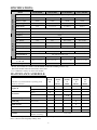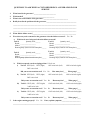
1
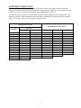
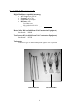
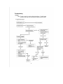
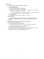
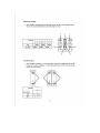
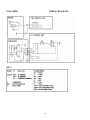
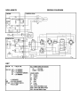
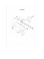
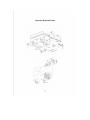
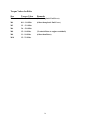
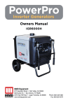
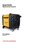
SERVICE MANUAL
GENERATORS
NGK-2900H, NGK-4300H,
NGK-6000H, NGK-7000H
MMD Equipment Inc.
121 High Hill Road
Swedesboro, NJ 08085
Tel: (800) 433-1382
Fax: (856) 467-5235
www.mmdequipment.com
TABLE OF CONTENTS
Safety Precautions
1
Specifications and Maintenance Schedule
2
Repair Questionnaire
3
Pre-Operation Checks
5
Starting Procedures
5
Using A.C. Electric Power
6
Stopping Procedures
7
Component Function
GFCIs
Circuit Breakers
Idle Control
Oil Sensor
7
7
8
8
Wattage Information
8
Extension Cord Usage
9
Special Tools
10
Disassembly Instructions
11
Assembly Instructions
14
Troubleshooting Trees
Engine
Generator
18
19
Detailed Troubleshooting Instructions
20
Test Values for Rotor, Stator, and Condensers
23
Full Power Switch and Circuit Breaker
25
Wiring Diagrams
26
Exploded Views of Generator
32
Torque Values
34
SAFETY PRECAUTIONS:
Your safety is very important to us. While we cannot warn you about every possible hazard
associated with operating your NAC portable generator, following the precautions listed below
will assist you in operating your NAC generator safely. It is the operator’s responsibility to be
familiar with and to follow these important safety precautions.
1. Use extreme caution near gasoline and other flammables.
• Do not fill the fuel tank while the engine is running.
1 WARNING! Do not smoke or use open flame near the generator.
1 WARNING! Do not place flammables such as gasoline, oily rags, straw, trash, or matches near the
generator.
•
Take care not to spill fuel on the generator when re-fueling. If fuel is spilled, wipe it off and allow it
to dry completely.
2. Operate the generator in a well-ventilated area.
1 WARNING! Engine exhaust contains poisonous carbon monoxide gas, which can be fatal if inhaled.
1 WARNING! Do not operate the generator indoors. If the generator must be operated indoors, the area
MUST be well ventilated and EXTREME CAUTION must be taken to prevent inhalation
of poisonous carbon monoxide gasses.
•
•
Do not enclose the generator or cover it with a box. The engine and generator are air-cooled and may
overheat if operated in an enclosed space.
Keep the generator at least 3 feet (1 meter) from building walls and other equipment during operation.
3. Operate the generator on a dry, level surface.
•
Operating the generator on an inclined surface may cause the splash lubrication system to operate
improperly. The engine oil may flow away from the oil scraper and over the oil sensor. Therefore, the
oil sensor will not stop the engine, even though there is no oil lubricating the engine components. This
could cause the engine to seize and is not covered under warranty.
4. Always operate the generator in a dry environment.
1 WARNING! Do not operate the generator in the rain, snow, or with wet hands. Severe electrical shock
may occur.
1 WARNING! Do not clean the generator with a pressure washer or any other water hose. Use a damp
cloth to wipe down the generator, and be especially careful not to get water into the
receptacles.
1 WARNING! Ensure there is no electrical wiring underneath the generator frame. Vibration from the
generator frame could wear through the wiring and cause sparks, fire, or shock hazard.
5. Additional safety information.
1 WARNING! Do not connect the generator directly to household or other indoor wiring or to any
commercial power line. This could cause fatal injuries to Utility Service Personnel or
damage to the generator. A licensed electrician must install a Manual Transfer Switch to
the main circuit breaker panel in order to use a generator for back-up power.
•
•
Although NAC generators are neutral grounded to the frame and should provide more than adequate
safety, use a grounding rod in accordance with local and OSHA safety requirements for optimum
grounding.
The muffler and engine crankcase are extremely hot during and after operation. Allow the engine
adequate time to cool before touching the muffler or crankcase.
1
SPECIFICATIONS:
Model
NGK-2900H
NGK-7000H/E
Max AC output
2900W
4300W
6000W
7000W
Rated AC output
2400W
3800W
5000W
6000W
Rated voltage
120 V
120/240 V
120/240 V
120/240 V
Rated current
20 A
31.7/15.9 A
41.7/20.8 A
50/25 A
Single
Phase
Condenser type
Voltage regulation
60 Hz
Frequency
Honda GX-160
Honda GX-240
Honda GX-340
Honda GX-390
Spec. number
ED2
ED2
ED6 / EDD2
ED6 / EDD2
Horsepower
5.5
8.0
11.0
13.0
3.0 gal.
4.5 gal.
4.5 gal.
4.5 gal.
Model
ENGINE
NGK-6000H/E
Brushless, 2-pole, self-exciting, revolving field type
Type
GENERATOR
NGK-4300H
Fuel tank capacity
Unleaded gasoline (86 Octane or higher)
Recommended fuel
0.63 US qt.
Oil capacity
1.16 US qt.
1.16 US qt.
1.16 US qt.
SAE 10W-30 API SF or SG
Recommended oil
Starting system
Recoil
Recoil
Recoil or electric*
Recoil or electric*
Dimensions (in.)
(L x W x H)
22.4 x 17.3 x 18.9
24.2 x 20.2 x 20.1
26.0 x 21.3 x 20.5
26.0 x 21.3 x 20.5
Dry weight
95 lbs.
150 lbs.
176 lbs.
191 lbs.
* Electric start models are available as NGK-6000HE AND NGK-7000HE generators only.
Recoil start models cannot be converted to electric start.
**Use a GROUP 51 battery on electric start models.
MAINTENANCE SCHEDULE:
REGULAR SERIVCE PERIOD
Perform at every indicated month or operating period,
whichever comes first.
Each
use
First
month
or
20 hrs.
Every 3
months
or
50 hrs.
Every 6
months
or
100 hrs.
Every
year
or
300 hrs.
•
Check level
Engine oil
•
Change
•
•
Inspect
Air cleaner
•ℵ
Clean
Fuel strainer cup
Clean
Spark plug
Inspect-Clean
•
•
Spark arrester
Clean
•
Valve clearance
Check-Adjust
Fuel tank and filter
Clean
Fuel line
Inspect
(Replace if necessary)
•
•
Every 2 years
* For detailed engine information, refer to the Honda Engine Shop Manual.
Note: ℵ Service more frequently in dusty areas.
2
QUESTIONS TO ASK WHEN A CUSTOMER BRINGS A GENERATOR IN FOR
SERVICE
1.
What brand is the generator? ___________________________
2.
Which model? ______________________________________
3.
What is the serial number of the generator? ______________________________
4.
Briefly describe the problem with the generator._____________________________________
______________________________________________________________________________
______________________________________________________________________________
______________________________________________________________________________
5.
When did the failure occur?______________________________________________________
6.
Were there any tools connected to the generator when the failure occurred?
a.
Which tools were being used when the failure occurred?
Tool #1
Quantity used:______
Brand: ___________________
Model: ___________________
Running amps (found on tool nameplate):_____
Tool #3
Quantity used:______
Brand: ___________________
Model: ___________________
Running amps (found on tool nameplate):_____
b.
Yes No
Tool #2
Quantity used:______
Brand: ___________________
Model: ___________________
Running amps (found on tool nameplate):_____
Tool #4
Quantity used:______
Brand: ___________________
Model: ___________________
Running amps (found on tool nameplate):_____
Which receptacle was the tool plugged into? Circle one
i)
Tool #1: GFCI (left)
GFCI (right)
120V twist-lock (left)
120V twist-lock (right)
240V twist- lock
Did you use an extension cord? Yes
ii)
Tool #2: GFCI (left)
GFCI (right)
No
How many feet?____ What gauge?____
120V twist-lock (left)
120V twist-lock (right)
240V twist- lock
Did you use an extension cord? Yes
iii)
Tool #3: GFCI (left)
GFCI (right)
No
How many feet?____ What gauge?____
120V twist-lock (left)
120V twist-lock (right)
240V twist- lock
Did you use an extension cord? Yes
iv)
Tool #4: GFCI (left)
GFCI (right)
No
How many feet?____ What gauge?____
120V twist-lock (left)
120V twist-lock (right)
240V twist- lock
Did you use an extension cord? Yes
7.
Is the engine running properly? Yes
No
No
How many feet?____ What gauge?____
If not, explain symptoms._______________________
____________________________________________________________________________________________
3
SERVICE QUESTIONAIRE PAGE 2
8.
Did the circuit breaker trip? Yes No If yes, which one? 30A (left)
Main
a.
Did you reset the circuit breaker and try to continue using the generator? Yes No
b.
If yes, did the circuit breaker trip again? Yes No
c.
If yes, how long did it take for the breaker to trip again?
5 min.
d.
9.
30A (right)
Immediately
30 sec.
1min.
2 min.
other_______
How many times did you try to reset the breaker?
1
5
10
20+
Did the GFCI trip? Yes No
a.
Did you reset the GFCI and try to continue using the generator? Yes No
b. If yes, did the GFCI trip again?
10. Was the IDLE CONTROL SWITCH
Yes No
On or Off
11. Which position was the FULL-POWER SWITCH in?
120
120/240
12. What was the approximate temperature where the generator was operating? _______
13. What were the weather conditions where the generator was operating?
4
Rain
Snow
Dry
PRE-OPERATION CHECKS:
Note: Before performing pre-operational checks, ensure the generator is located on a clean and level surface
with the engine stopped.
INSPECT THE OVERALL CONDITION OF THE GENERATOR
1. Look around the generator for signs of oil or gasoline leaks.
2. Ensure the cooling vents on the engine’s recoil assembly and generator head are free of debris or
obstructions.
3. Check that all nuts, bolts, and screws are tightened.
4. Inspect the generator for any signs of damage (especially on the control panel, fuel tank, and fuel hoses).
5. Ensure the green, grounding wire located between the aluminum generator cover and the frame is
securely connected.
CHECK ENGINE OIL
Note: The generator MUST be located on a level surface with the engine stopped when checking the oil
level. Failure to do so could result in improper lubrication of the engine, which could cause engine
damage!
1. Remove the oil dipstick and wipe it clean.
2. Insert and remove the dipstick (without screwing it into the filler neck).
3. Fill the crankcase to the lower edge of the dipstick hole with the recommended oil. Honda recommends
that you use API SERVICE category SF or SG oil.
¾ SAE 10W-30 is recommended for general use (-5°F to 110°F). (Consult the Honda engine owner’s
manual for additional information)
4. Inspect the color of the oil. If the oil appears excessively dark, cloudy, or has a metallic tint, change the
oil. (Consult the Honda engine owner’s manual for instructions about changing the oil)
CHECK AIR CLEANER
1. Remove the air cleaner cover and inspect the foam filter (element). Clean or replace dirty filters. If the
foam filter is damaged, replace the filter.
¾ To clean the filter, wash it in warm soapy water, rinse, and allow it to dry thoroughly. Coat the
filter in engine oil, then squeeze out the excess. The engine will smoke when started if too much oil
is left in the filter.
CHECK ENGINE FUEL
1WARNING! Never check the fuel level or refuel the tank while the engine is running, near open flame, or
while smoking.
1. Remove the fuel cap and check fuel level. If level is low, refuel with fresh, clean, unleaded gasoline (86
Octane or higher).
STARTING PROCEDURES:
RECOIL START MODELS
1. Ensure the switches on the generator control panel are in the correct position prior to starting the engine.
a) All CIRCUIT BREAKERS should be turned off.
b) IDLE CONTROL switch should be turned off.
c) Engine RUN/STOP switch should be switched to “RUN.”
2. Open the fuel cock located at the base of the fuel tank just above the recoil starter. When the fuel cock
lever is perpendicular to the ground (straight up & down), the fuel cock is open.
3. Close the choke valve by pulling the CHOKE LEVER.
4. Grasp the black starter handle and pull slowly until you feel resistance. Return the starter handle to its
original position, then pull briskly. Slowly return the starter handle to its original position.
5. Once the engine has started, push the CHOKE LEVER back to its original position.
6. Allow the engine to warm up for 3 minutes before you use the generator.
5
ELECTRIC START MODELS
1. Follow steps 1) through 3) of the RECOIL START section. (Disregard step 1c)
2. Insert the key into the key slot and turn it clockwise to the “START” position.
3. Release the key as soon as the engine starts (the key should automatically return to the “RUN”
position).
CAUTION! If the engine does not start within 5 seconds, release the key. Wait at least 30
seconds and try to start the engine again.
Do not turn the key to the “START” position while the engine is running.
4. Once the engine has started, push the CHOKE LEVER back to its original position.
5. Allow the engine to warm up for 3 minutes before you use the generator.
USING A.C. POWER FROM THE GENERATOR:
1.
Single Voltage (120V only)
a) Leave the CIRCUIT BREAKERS off until your electrical appliances are properly connected
to the generator.
b) Turn off the switches on all electrical appliances before connecting them to the generator.
Note: Before plugging any appliances into the generator, check the wattage of each appliance to be
used. The TOTAL wattage of all appliances should not exceed the rated output of the
generator.
c) Insert the plugs from your electrical appliances into the generator.
Note: To use power from the round, locking receptacles, insert the plug into the receptacle and turn it
clockwise to lock the plug.
d) Place the FULL POWER switch in the 120V position (The 240V receptacle can NOT be used
when the FULL POWER switch is in the 120V position).
e) Switch the CIRCUIT BREAKERS on.
2.
Dual Voltage (120V/240V)
a) Follow steps a) through c) above.
b) Place the FULL POWER switch in the 120V/240V position.
c) Switch the CIRCUIT BREAKERS on.
CAUTION! The FULL POWER switch should always be kept in the 120V position unless you
are using the 240V receptacle.
6
STOPPING PROCEDURES:
1.
2.
3.
4.
Ensure all appliances are turned off.
Place CIRCUIT BREAKERS in the “OFF” position.
Turn the IDLE CONTROL switch to the “OFF” position.
Before stopping the engine, allow it to run for at least three minutes with all appliances turned off, so the
engine can cool down.
5. Once the engine has cooled down, turn the ON/OFF switch on the generator control panel to the “OFF”
position.
6. On Electric Start generators (NGK-6000HE & NGK-7000HE), turn the key switch to the “OFF”
position.
7. Close the fuel cock located at the base of the fuel tank just above the recoil starter. When the fuel cock
lever is parallel to the ground (left to right), the fuel cock is closed.
Note: If the engine does not stop when the ON/OFF switch is placed in the “OFF” position, there are two
ways to stop the engine.
a) Close the fuel cock located at the base of the fuel tank just above the recoil starter. When the fuel
cock lever is parallel to the ground (left to right), the fuel cock is closed. After a few minutes, the
engine will stop.
b) If you need to stop the engine quickly, grasp the spark plug cap and gently pull it off the spark plug.
This will stop the engine immediately.
Note: If you are not going to use the generator for 48 hours or more, stop the engine by following the
instructions in step a) above. This will prevent old gas from clogging fuel passages in the carburetor.
FUNCTION OF ADDITIONAL FEATURES:
GFCI RECEPTACLES
GFCI stands for Ground Fault Circuit Interrupter. The GFCI compares the amount of current leaving the
GFCI receptacle with the amount of current returning to the GFCI receptacle. If the amount of current
leaving the GFCI receptacle exceeds the amount of current returning to the GFCI receptacle by 5 milliamps
or more, the GFCI will trip. The GFCI is designed to stop the flow of electricity leaving the receptacle, in
order to protect the person operating the appliances that are plugged into the GFCI. The GFCI will not limit
the amount of current experienced if you are shocked, but it will limit the duration of the shock. This is why
it is important to regularly test the GFCIs on your NAC generator.
TESTING GFCIs
1. The generator must be running with the CIRCUIT BREAKERS in the “ON” position to test the GFCIs.
2. Press the TEST button located between the two outlets on the GFCI. The RESET button should pop out.
• If the RESET button does not pop out, the receptacle may be defective. Do not use the generator;
contact your authorized NAC service center for repair.
3. To restore power, depress the RESET button until an audible click is heard. The TEST and RESET
buttons should be level to each other.
• If the GFCI trips during operation, turn the CIRCUIT BREAKERS off and unplug the appliances
connected to the GFCI. Test the appliance for ground faults and repair faulty appliances before reconnecting them to the GFCI.
• If the GFCI continues to trip, stop the generator and contact your authorized NAC service center.
CIRCUIT BREAKERS
The circuit breakers on NAC generators are “NO-FUSE” circuit breakers. These circuit breakers protect the
GENERATOR from damage due to overload or short circuit in the appliance. They do NOT protect the
operator from shock or electrocution. When the circuit breaker trips, there is no voltage present at the
receptacles.
7
WHAT TO DO IF THE CIRCUIT BREAKER TRIPS:
If the circuit breaker trips during operation, the generator may be overloaded or the appliance being used is
defective.
1. Add the wattage from all appliances being used on the generator. If the total wattage exceeds the
RATED output of the generator, the generator is overloaded.
• Reduce the number of appliances used on the generator.
• Use a NAC generator with higher wattage output.
2. If the total wattage being used is less than the RATED output of the generator, check the appliance for
defects and repair faulty appliances before reconnecting them to the generator.
3. If the circuit breaker continues to trip, do not use the generator. Contact your authorized NAC service
center.
IDLE CONTROL SYSTEM (NGK-4300H/6000H/7000H):
The idle control system automatically reduces the engine speed to improve fuel economy, reduce noise, and
prolong engine life.
HOW TO USE THE IDLE CONTROL SYSTEM:
1.
After the engine has warmed up, place the IDLE CONTROL switch in the “ON” position.
• The engine will idle at approximately 2400 rpm until the appliance is turned “ON.”
• 1~2 seconds after the appliance is activated, the engine speed will increase to the rated rpm.
• 5~10 seconds after the appliance is turned off, the engine will idle back down.
2.
Turn the IDLE CONTROL switch “OFF” when you are finished using the appliances, and allow the
engine to cool down for at least 3 minutes before stopping the engine.
OIL SENSOR
The oil sensor is designed to protect the engine from damage if you forget to maintain the proper oil level.
• If the oil level in the engine drops too low, the oil sensor will automatically stop the engine.
• If the engine stops automatically, check to ensure there is fuel in the gas tank and oil in the engine.
Refill with fresh gasoline and/or oil if necessary and re-start the engine.
• If the engine fails to start, follow the steps in the Troubleshooting section of this manual.
WATTAGE INFORMATION:
Some appliances require more power to start than they do during operation. All NAC generators have an
overload capacity designed to allow overload for short periods. It is extremely important to use the proper
size generator for the appliances you need to use. The information below gives the additional wattage
required by certain appliances. The additional starting wattage required by these appliances must be
considered when choosing the NAC generator best suited for your needs.
1) Incandescent lamps require no additional wattage to start.
2) Fluorescent lamps and mercury lamps require 1.2 to 2 times the running wattage to start.
3) Motor driven tools require 1.2 to 3 times the running wattage to start.
4) Motors that start under heavy loads such as compressors, refrigeration systems, and submersible pumps
require high current for long periods while starting. These appliances require 3~5 times the running
wattage to start.
• Check with the manufacturer of the appliance for specific information about the running and
starting wattage requirements.
Note: To determine running wattage, multiply the amperage on the tool nameplate by the voltage used. To
determine starting wattage, multiply the running wattage by the factors listed above.
• For example: A 5 amp submersible pump that runs on 120 volts has a running wattage of 600
watts (5A x 120V = 600W) and requires about 3000 watts to start (600W x 5 = 3000W).
8
EXTENSION CORD USAGE:
It important to use the proper gauge extension cord with any power tool or other electrical equipment.
Improper selection of extension cords can reduce the voltage leading to your tools. Low voltage at the tool
results in loss of speed and power, overheating, and possible damage to the tool.
To assure the proper selection of extension cords, locate the ampere rating from the tool nameplate. Then
apply the amperage from this nameplate to the chart below to determine the proper gauge for the length of
cable you are using. Always use UL approved extension cords.
CONTINUOUS LOAD
AMPERES
2
3
4
5
6
8
10
12
14
16
18
20
22
25
30
MAXIMUM GUAGE (AWG)
WATTS
@ 120V
240
360
480
600
720
960
1200
1440
1680
1920
2160
2400
2640
3000
3600
@ 240V
480
720
960
1200
1440
1920
2400
2880
3360
3840
4320
4800
5280
6000
0~50 feet
18
18
18
18
16
14
14
14
12
12
12
10
10
8
9
50~100 feet
18
16
14
14
12
10
10
10
10
8
8
8
6
100~150 feet
16
14
12
12
12
10
10
10
8
8
8
6
Special Tools Recommended:
Digital Multimeter capable of measuring:
•
•
•
•
•
AC Voltage up to 250VAC
Frequency up to 70Hz
Capacitance up to 100µF
Resistance with:
Low-Ohms range
Max resolution of 0.01Ω
True RMS feature is recommended but not necessary
Rotor Puller Kit (Available from NAC Construction Equipment)
Part Number:
K-RPK
Test Harness Kit (Available from NAC Construction Equipment)
Part Number:
K-THK
Tachometer
Contact-less type or one that clamps to the ignition wire is preferred
Rotor Puller Kit
10
Test harness Kit
Troubleshooting the Generator:
1. Inspect the overall condition of the generator
a. Does it appear that the generator has been properly maintained?
b. Check the entire generator for damage, paying extra attention to:
i) Frame- Look for abnormal bends, dents, or other indications that the generator has been
dropped or abused (the generator should not wobble on a flat surface).
ii) Control Panel- Inspect the panel for damage and loose or missing bolts or screws. Ensure
all receptacles, switches, and circuit breakers are not broken.
iii) Control Boxes- Inspect both control boxes behind the control panel for damage.
iv) Engine and Generator Isolators-Look to see if the isolators are twisted or damaged (this
may indicate the generator was dropped).
v) Muffler Bracket- Inspect the bracket for damage.
vi) Nuts and Bolts- Check all nuts, and bolts for tightness.
vii) Engine and Generator Cooling Fins- Remove any obstructions from the cooling fins.
viii) Air Cleaner- Inspect and clean the engine air cleaner if necessary.
ix) Oil- Check the engine oil level. Look for signs of neglect or engine wear (oil that is
excessively dirty or cloudy, or oil with a metallic tint). Refill crankcase or change the
engine oil if necessary.
x) Gas- Ensure the tank has plenty of FRESH gasoline. Inspect the engine and generator for
signs of gas or oil leaks.
2. Start the generator
a.
b.
c.
d.
e.
Always start the generator at No-Load by disconnecting all tools from the receptacles.
Ensure all the circuit breakers are switched OFF.
The FULL-POWER SWITCH should be in the 120 position (NOT the 120/240 position).
The IDLE CONTROL SWITCH should be in the “OFF” position.
Place the ENGINE SWITCH in the “RUN” position and start the engine (allow the engine to
warm up for at least five minutes at no-load).
3. Begin testing the generator
a. Check the engine speed.
i) It should be between 3700~3800rpm at no-load. If not, ensure the IDLE CONTROL
SWITCH is “OFF.” If the rpm is not between 3700 and 3800rpm, refer to the Honda Engine
Shop Manual and adjust the engine speed to the proper rpm.
b. The PILOT LAMP should be illuminated.
c. Turn all the circuit breakers “ON.”
d. Test all GFCIs by pressing the “TEST” button in the center of the receptacle.
i) If the “RESET” button on the GFCI pops out, the GFCI is functioning properly. Press the
“RESET” button until you hear a “click” and continue testing.
ii) If the “RESET” button does NOT pop out, ensure all circuit breakers are turned “ON” and
attempt to test the GFCI again.
(1) If the generator has two GFCIs and only one of the GFCIs tests properly, replace the
defective GFCI.
e. Test the frequency of the generator at the receptacles. It should be roughly between 62~63Hz at
No-Load. (If the engine rpm was set between 3700~3800rpm, the frequency should be accurate).
20
3. Begin testing the generator (Continued)
f.
Test the AC voltage from ALL receptacles.
i) The voltage at each GFCI and the 120V/30A twist-lock receptacles should be between
124~132VAC.
ii) The voltage at the 240V twist-lock should be as follows:
• Ground ~ X hot = 124~132 VAC
• Ground ~ Y hot = 124~132 VAC
• Neutral ~ X hot = 124~132 VAC
• Neutral ~ Y hot = 124~132 VAC
• Ground ~ Neutral = 0 VAC
• X hot ~ Y hot = 0 VAC
g. Place the FULL POWER SWITCH in the 120/240V position and test the voltage from ALL
receptacles again.
i) The voltage at each GFCI and the 120V/30A twist-lock receptacles should be between
124~132 VAC.
ii) The voltage at the 240V twist-lock should be as follows:
• Ground ~ X hot = 124~132 VAC
• Ground ~ Y hot = 124~132 VAC
• Neutral ~ X hot = 124~132 VAC
• Neutral ~ Y hot = 124~132 VAC
• Ground ~ Neutral = 0 VAC
• X hot ~ Y hot = 245~260 VAC
h. If the voltage is correct at all the receptacles except one, that receptacle is defective. Replace the
receptacle.
i. If the voltage is lower than specified above, check the engine rpm.
j. If the voltage from ALL receptacles is still low, stop the engine and follow the troubleshooting
steps below.
4. No or Low Voltage
a.
b.
c.
d.
FIRST, ENSURE THE ENGINE SPEED IS BETWEEN 3700RPM AND 3800RPM!
Remove the End Cover from the generator head (three screws).
Separate the plastic connectors from the Stator.
Install the Test Adapters (sold as an accessory kit from NAC) by matching the wire colors on the
Test Adapters to the wire colors at the stator connectors.
e. Ensure the connectors are secure.
f. Start the engine and allow it to warm up for a few minutes.
g. Measure the AC voltage from the leads of the Test Adapters.
WARNING!
Do not touch any metal portion of the meter leads or connectors while
the engine is running. There is live voltage produced from the
generator, which could cause severe shock or electrocution!
i) The AC voltage between the Blue and White leads should be 124~ 132VAC.
ii) The AC voltage between the Brown and Yellow leads should be 124~ 132VAC.
(1) If the voltage in steps “i” and “ii” is lower than 120VAC, test the Condensers, Stator, and
Rotor (refer to step 4h).
(2) If the voltage measured in steps “i” and “ii” are within tolerance, the Rotor, Stator, and
Condensers are functioning properly.
• Possibly, one of the connectors at the Stator was loose when testing the voltage at the
receptacles. Remove the Test Adapters and securely connect the Stator wires. Retest
the voltage at the receptacles (step 3f-g).
21
4. No or Low Voltage (Continued)
(3) If the voltage is still low at the receptacles, the defective component is in the Control
Panel.
(a) Test the Circuit Breakers.
(i) Disconnect the Circuit Breaker and check for continuity.
1. When the Circuit Breaker is “ON” there should be continuity between the
terminals.
2. When the Circuit Breaker is “OFF” there should be no continuity between
the terminals.
• Replace the Circuit Breaker if it does not pass the tests in the steps listed
above.
(b) Verify that all wiring in the control panel is correct (refer to the appropriate wiring
diagram).
(c) Test the Full POWER SWITCH (refer to the wiring diagram).
h. Testing the Condensers, Stator, and Rotor
(1) Condensers
(a) Remove the End Cover from the generator and disconnect the plastic connector with
the two black wires.
(b) Discharge the condensers by shorting the two black wires leading into the control
box. Failure to do so may result in inaccurate readings.
(c) Use a meter capable of measuring capacitance up to 100µF and measure the
capacitance of the condensers (values are listed in the table below).
(d) If the Condensers are more than 10% above or below their rated capacitance, they are
defective.
(2) Stator
(a) Use a high quality meter capable of measuring resistance values as low as 0.1Ω.
(b) Touch and hold your meter leads together for at least 10 seconds. Record the value
shown on the meter display (It will be somewhere between 0.1Ω and 0.3Ω). You
MUST subtract this value from any resistance readings you measure.
(c) If your meter has a manual setting for range, set the range to the lowest setting.
(d) Test the stator by measuring the resistance between the wires of each connector
(values are listed in the table below).
(3) Rotor
(a) Touch and hold your meter leads together for at least 10 seconds. Record the value
shown on the meter display (It will be somewhere between 0.1Ω and 0.3Ω). You
MUST subtract this value from any resistance readings you measure.
(b) If your meter has a manual setting for range, set the range to the lowest setting.
(c) Test the rotor by measuring the resistance between one of the two posts of the rotor
diode, to one of the posts on the other diode. This can be done without disassembling
the generator, but it is somewhat difficult.
(d) If you cannot obtain accurate readings from the rotor while the unit is assembled,
follow the instructions for removing the stator, and test the rotor.
(e) Do NOT remove the diodes or de-solder the wires attached to the diodes.
(f) Ensure you have a good contact point on the diode posts, and do not allow the meter
leads to touch any other metal portion of the generator. Doing so will give erroneous
readings.
• Values are listed in the table below.
22
h) Testing the Condensers, Stator, and Rotor (Continued)
(4) If all values are within the ranges listed below, measure the insulation resistance of
the stator and rotor with a Megger Tester. The insulation resistance should be
greater that 10MΩ.
(a) Replace any component that fails the insulation test.
ROTOR
MODEL
RESISTANCE
NGK-2900H
3.25 ~ 4.0 Ω
NGK-4300H
4..9 ~ 6.0 Ω
NGK-6000H/HE
5.5 ~ 6.7 Ω
NGK-7000H/HE
5.9 ~7.2 Ω
STATOR
AC WINDINGS
MODEL
CONDENSER WINDING
BLUE-WHITE
YELLOW-BROWN
BLACK-BLACK
NGK-2900H
0.5 ~ 0.6Ω
0.5 ~ 0.6Ω
2.0 ~ 2.4 Ω
NGK-4300H
0.4 ~ 0.5 Ω
0.4 ~ 0.5 Ω
1.3 ~ 1.6 Ω
NGK-6000H/HE
0.4 ~ 0.5 Ω
0.4 ~ 0.5 Ω
0.8 ~ 1.0 Ω
NGK-7000H/HE
0.17 ~ 0.21 Ω
0.17 ~ 0.21 Ω
0.4 ~ 0.44 Ω
CONDENSERS
MODEL
CAPACITANCE
NGK-2900H
15 µF
(±10%)
NGK-4300H
20 µF
(±10%)
NGK-6000H
15 µF x 2
(±10%)
NGK-7000H
20 µF x 2
(±10%)
23
5. Idle Control
a) If the engine will not idle down when the switch is ON.
i) Test the engine solenoid
(1) Ensure the solenoid connectors are not loose.
(2) Disconnect the 2P connector at the Solenoid.
(3) Connect the Green/White wire to the positive (+) terminal of a 6.0 V battery and
the Green wire to the negative (-) terminal.
• If the solenoid plunger moves toward the solenoid body, the solenoid is good.
• If the solenoid does not move, replace the solenoid.
ii) Test the lamp coil
• Measure the resistance of the two leads (0.36Ω ~ 0.46Ω).
iii) Test the switch
• There should be continuity between terminals 1 and 2 when the switch is on.
iv) If the above components test GOOD, check the wiring and replace the Idle
Board.
b) If the engine speed will not increase when the tool is turned on.
ii) Ensure the circuit breakers are ON.
iii) Test the GFCI by pressing the TEST button.
(1) If the RESET button pops out, push it back in and try to use the tool again.
(2) If the RESET button does not pop out, replace the GFCI.
iv) Ensure the engine rpm at low idle is set to 2400.
v) Open the control panel and check the wiring. The blue and yellow wires must pass
through the coil on the Idle Control Board in the same direction.
vi) If the wiring is correct, replace the idle control board.
24
NGK-2900H
WIRING DIAGRAM
KEY
26
NGK-4300H
WIRING DIAGRAM
KEY
27
NGK-6000H
WIRING DIAGRAM
KEY
28
NGK-7000H
WIRING DIAGRAM
KEY
29
NGK-6000HE
WIRING DIAGRAM
KEY
30
NDK-4100YE
KEY
WIRING DIAGRAM
NDK-6000YE
KEY
WIRING DIAGRAM
NGK-7000HE
WIRING DIAGRAM
KEY
31
Torque Values for Bolts:
Size
Torque Value
Remarks
M4
0.4 ~ 0.6 ft/lbs.
(To attach plastic End Cover)
M4
0.8 ~ 1.8 ft/lbs.
(Other than plastic End Cover)
M5
1.3 ~ 2.9 ft/lbs.
M6
3.6 ~ 5.8 ft/lbs.
M8
15 ~ 18 ft/lbs.
(To attach Rotor to engine crankshaft)
M8
11 ~ 18 ft/lbs.
(Other than Rotor)
M10
15 ~ 22 ft/lbs.
34