1
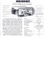
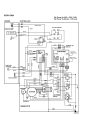
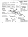
OWNER’S MANUAL
GENERATOR / WELDER
NGW-190H
MMD Equipment Inc.
121 High Hill Road
Swedesboro, NJ 08085
Tel: (800) 433-1382
Fax: (856) 467-5235
www.mmdequipment.com
STARTING THE NGW-190H GEN/WELDER
READ HONDA ENGINE OWNER'S MANUAL BEFORE OPERATING GEN/WELDER
1) Place generator on a stable and level surface.
2) Inspect engine for oil or gas leaks.
3) Check engine oil. (See Honda engine owner's manual)
NGW-190H uses a 13hp Honda GX-390 engine. (Oil capacity is 1.16 U.S. quarts)
4) Fill fuel tank with fresh, clean, unleaded gasoline (4.5 gallons)
5) Check gen/welder control panel. Circuit breakers should be "off", idle control switch
should be "off", and on-off switch should be "on."
6) Turn fuel cock to the open position (lever is vertical)
7) Pull choke lever out (choke is on with lever pulled out)
8) Pull starter grip lightly until you feel resistance. Return the grip gently to its original
position, and then pull briskly. Return the grip gently. Repeat this process until the
engine starts.
9) Push choke lever inward (choke is off)
10) Allow the engine to run for 3-5 minutes before connecting any equipment or welding.
11) Place circuit breakers in the "on" position.
3
USING A.C. RECEPTACLES
READ HONDA ENGINE OWNER'S MANUAL BEFORE OPERATING GEN/WELDER
1) Check pilot lamp is illuminated.
2) Ensure all appliances are turned off before connecting them to the generator.
3) Insert appliance plugs into receptacles on generator.
•
Check the amperage of the receptacles being used and be sure not to exceed that amperage
GFCI
NEMA L14-10R
NEMA L5-30R
20 amps of 120V
10 amps of 240V (four-pronged locking receptacle)
30 amps of 120V (three-pronged locking receptacle)
NOTE ON OPERATION OF THE FULL-POWER SWITCH:
When the full-power switch is placed in the "AC 120/240" position, only half the rated
current may be drawn from the 120V receptacles, while all the rated current may be drawn
from the 240V receptacle. When the full-power switch is placed in the 120V position, all the
rated current may be drawn from each of the 120V receptacles, but no current may be drawn
from the 240V receptacle.
NOTE:
When the circuit breaker trips during operation, the generator is overloaded or the appliance is
defective. Turn the generator off immediately and calculate the total wattage being used.
(voltage x total amperage = wattage)
The rated A.C. output varies from 600W to 3300W depending on the D.C. amperage
being used simultaneously.
♦ Rated A.C. output if not welding is 3300W
♦ Rated A.C. output while welding at 180A simultaneously is 600W
For example:
The full power switch is in the 120V/240V position, and the generator is being used to power
a 5A appliance from the GFCI and a 10A appliance from the 240V receptacle.
Wattage consumed from GFCI is:
5A x 120V = 600W
Wattage consumed by the 240V receptacle is:
10A x 240V=2400W
Total wattage consumed is:
600W + 2400W =3000W
If the total wattage exceeds the rated A.C. output of the gen./welder (see above), reduce the
number of tools being used, or use a larger generator. If the total wattage does not exceed the
rated A.C. output of the gen./welder, check the appliances for shorts. If all appliances test
normal, take the gen/welder to an authorized service center for repair.
4
PRECAUTIONS FOR D.C. WELDING
READ HONDA ENGINE OWNER'S MANUAL BEFORE OPERATING GEN/WELDER
1) Electric shock is extremely dangerous! Please adhere to the following precautions.
a) Wear protective clothing such as welding gloves, welding apron, and face shield.
Filter lens should conform to ANSTI Z87.1 Standard.
b) Damaged welding cables may cause shorting to occur, or electrical shock to personnel.
Always inspect cables for damage before connecting them to the welding lugs!
c) Never touch welding lugs while engine is running!
d) Always ensure the protective cover over the welding lugs is closed whenever the
engine is running!
e) Never operate the gen/welder in any wet area!
2) Fumes from engine and welder are noxious and may cause sickness or even death!
a) Avoid breathing fumes from engine and welder.
b) Ensure adequate ventilation near gen/welder, especially when welding on galvanized
lead or cadmium-plated steel and other metals that produce toxic fumes.
3) Avoid circumstances that could cause fire or explosion!
a) Keep the area clear of combustible material. Sparks from welding can ignite
flammables.
b) Do not weld and heat drums, tanks, or any enclosed containers unless precautions have
been taken to keep fumes from concentrating inside.
c) Keep approved fire extinguishers readily available when welding.
5
USING D.C. OUTPUT FOR WELDING
READ HONDA ENGINE OWNER'S MANUAL BEFORE OPERATING GEN/WELDER
NOTE:
To avoid serious injury, never connect welding cables while engine is running!
1) Select the proper cables using the guidelines below.
The required cable size is determined by the amount of amperage used when welding and the
length of cable to be used. The longer the length of cable (or the higher the welding current),
the larger the diameter of the cable must be.
Length (ft.) 50
100
125
150
200
250
300
#3
#3
#3
#3
#3
#3
#3
#3
#3
#3
#3
#2
#3
#2
#1
#3
#1
#1/0
#2
#1
#1/0
Current (A)
100
150
180
2) Select the polarity of welding cables
The polarity, positive (+) or negative (-), is indicated at the welding lugs on the control panel.
Select the polarity according to the appropriate welding application.
Polarity
Connection method
Application
Electrode +…Grounding (base metal)
positive
-…Electrode holder
Welding structural steels or thick plates
Electrode +…Electrode holder
Negative -…Grounding (base metal)
Build-up welding
Arc welding thin plates
Arc welding stainless steel
3) Duty cycle for NGW-190H gen./welder.
This welder is not designed to withstand continuous welding. To avoid overloading the
gen./welder, adhere to the appropriate duty cycle. Duty cycle is a percentage of a 10-minute
period of time.
Welding current (A) 110 or less
120
140
170
190
Duty cycle (%)
80
60
50
40
100
Example: If the duty cycle is 40%, you can weld up to 4 minutes in a 10-minute period.
6
NGW190H WELDER
TROUBLESHOOTING
GUIDELINES
1. First, verify the engine rpm is set to 3750 rpm at no-load.
2. Then check the lamp coil from the Honda engine (0.36W ~
0.46W). This coil provides the initial excitation voltage for the
generator / welder (pages 8-2 and 8-6 of the Honda shop
manual for the GX-390 engine).
3. Next, check the brush length; they must be longer than 5 mm.
If the brushes are less than 5 mm long, the brush holder must
be replaced. Brushes should also move smoothly in and out of
the brush holder.
4. Ensure the brushes are smooth and the slip rings on the rotor
are also clean and smooth.
5. Measure the resistance between the two, slip rings on the
rotor. It should be between 7.1 Ohms ~ 7.2 Ohms. If the
resistance is outside these parameters, replace the rotor
(Ensure your readings are accurate!).
6. Measure the resistance of the stator coils. See attached
pages. If the resistance is outside these parameters, replace
the rotor (Ensure your readings are accurate!).
7. Test AVR.
8. Your multi-meter must be very accurate (to 0.01W). You must
also determine the resistance in your meter leads by holding
the tips of the leads together and recording the value from your
meter (probably 0.1 W or 0.2 W). Subtract this value from all
test values read on the meter display.