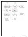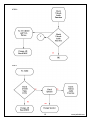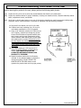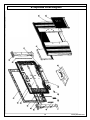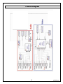
1
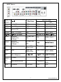
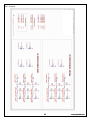
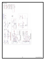
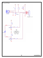
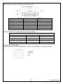
2007 LCD Models – North America
TLA-04011C, TLXB-4011, TLXB-4241
SERVICE MANUAL
Bezel covers vary by model
20070613
Important Service and Safety Information
Prior to using this service manual, please ensure that you have carefully
followed all the procedures outlined in the user's manual for this product.
(1)
Read all of these instructions.
(2)
Save these instructions.
(3)
Follow all warnings and instructions marked on the product.
(4)
Unplug this product from the wall outlet before cleaning. Do not use liquid cleaners or aerosol cleaners; use a
damp cloth for cleaning.
(5)
Do not use this product near water.
(6)
Do not place this product on an unstable cart, stand or table. The product may fall, causing serious damage to the
product.
(7)
Slots and openings in the cabinet and the back or bottom are provided for ventilation, to ensure reliable operation
of the product and to protect it from overheating, those openings must not be blocked or covered. The openings
should never be blocked by placing the product on a bed, sofa, rug, or other similar surface. This product should
not be placed in a built-in installation unless proper ventilation is provided.
(8)
This product should be operated from the type of power source indicated on the marketing label. If you are not
sure of the type of power available, consult your dealer or local power company.
(9)
This product is equipped with a 3-wire grounding type plug, a plug having a third (grounding) pin. This plug will
only fit into a grounding-type power outlet. This is a safety feature, if you are unable to insert the plug into the
outlet, contact your electrician to replace your obsolete outlet. Do not ignore the purpose of the grounding-type
plug.
(10) Do not allow anything to rest on the power cord. Do not locate this product where people will walk on the cord.
(11) If an extension cord is used with this product, make sure that the total of the ampere ratings on the product
plugged into the extension cord does not exceed 15 ampere.
(12) Never push objects of any kind into this product through cabinet slots as they may touch dangerous voltage points
or short out parts that could result in a risk of fire or electric shock. Never spill liquid of any kind on the product.
(13) Do not attempt to service this product yourself, as opening or removing covers may expose you to dangerous
voltage points or other risks. Refer all servicing to service personnel.
(14) Unplug this product from the wall outlet and refer servicing to qualified service personnel under the following
conditions: (0)
a. When the power cord or plug is damaged or frayed.
b. If liquid has been spilled into the product.
c. If the product has been exposed to rain or water.
d. If the product does not operate normally, when the operating instructions are followed. Adjust only
those controls that are covered by the operating instructions since improper adjustment of other
controls may result in damage and will often require extensive work by a qualified technician to
restore the product to normal operation.
e. If the product has been dropped or the cabinet has been damaged.
f. If the product exhibits a distinct change in performance, indicating a need for service. .
2
www.polaroid.com
Important Service and Safety Information
Service work should be performed only by qualified service technicians familiar with all safety
checks and these service guidelines:
ELECTRIC SHOCK HAZARD
Always disconnect AC power before servicing!
Never modify any circuit!
Never insert any objects into the holes in the TV case!
ELECTROSTATIC DISCHARGE (ESD)
Components inside an LCD or plasma TV are sensitive to static electricity. Before servicing the TV, follow these
guidelines:
•
•
•
•
•
Avoid static-causing surfaces such as carpeted floors, plastic, and packing foam.
Remove replacement components from their antistatic bags only when you are ready to use them. Do
not lay components on the outside of antistatic bags because only the inside of the bags provide
electrostatic protection.
Always hold components by their edges. Avoid touching the edge connectors. Never slide components
over any surface.
Wear a grounding wrist strap (available at most electronics stores) and attach it to a bare metal part of
your workbench or other grounded connection.
Touch a bare metal surface on your workbench or other grounded object before touching any
components.
NOTICE ABOUT REPLACEMENT PARTS
Many electrical and mechanical parts within LCD or plasma televisions are chosen for their
specific safety characteristics within the overall system. Replacing individual parts with
components rated for higher voltage or wattage can be dangerous!
Replacement parts must always be identical to those originally used in the television. Unauthorized substitute
parts may result in fire, electric shock, or other hazards.
3
www.polaroid.com
Important Service and Safety Information
PRECAUTIONS FOR USING LEAD-FREE SOLDER
Components within this television use lead-free solder (Sn-Ag-Cu). Whenever soldering, look at the markings
on boards and components within the television to determine the correct solder type according to the table
below.
5 LEAD-FREE (Pb-Free) CATEGORIES
The following categories are meant to describe the Pb-free 2nd level interconnect terminal finish, component
material, and/or the solder paste/solder used in board assembly:
e1 - SnAgCu (shall not be included in category e2)
e2 - Sn alloys with no Bi or Zn excluding SnAgCu
e3 - Sn
e4 - Precious metal (e.g., Ag, Au, NiPd, NiPdAu) (no Sn)
e5 - SnZn, SnZnx (no Bi)
e6 - contains Bi
e7 - low temperature solder (≤ 150 °C) containing Indium (no Bi)
e0, e8, e9 symbols are unassigned at this time.
When repairing components soldered with lead-free solder, ONLY use lead-free solder that matches the
symbol on the component. Using conventional lead solder may lead to damage or a short, which could result
in fire, electric shock, or other hazards.
Because the melting point of lead-free solder is higher than conventional lead solder, observe the following
guidelines when soldering with lead-free solder:
(1)
Always use a dedicated soldering bit for different types of solder. If a different type of solder comes in contact with
a lead-free solder bit, subsequent solder joints will no longer be lead free. Always clean the soldering bit after
every use.
(2)
Keep the soldering bit in contact with the just long enough to confirm a good solder joint. Leaving the bit in contact
with parts for an extended period may damage the components.
(3)
Because lead-free solder contains a higher concentration of tin, the tip of the soldering bit may be easily corroded
or damaged. Do not leave the bit powered on for extended periods. When the tip of the soldering bit is blackened
during use, clean the bit with steel wool or fine sandpaper. (0)
4
www.polaroid.com
Table of Contents
1.
2.
3.
4.
5.
6.
7.
8.
9.
10.
11.
Specifications..................................................................................................................................... 6
Operation ........................................................................................................................................ 10
Troubleshooting / Flow Charts .......................................................................................................... 16
Factory Mode Procedure........................................................................................................... 16
Polaroid Display Cell Defect Specification........................................................................................... 20
Before Returning This Product to the User......................................................................................... 21
Disassembly Procedure..................................................................................................................... 22
Stand and Control Box Removal................................................................................................ 23
Rear Cabinet Cover, LCD Panel and Front Bezel ......................................................................... 25
IR Board Removal and Replacement ......................................................................................... 32
Front/Side Control Buttons Removal and Replacement ............................................................... 33
Spare Parts Lists .............................................................................................................................. 34
Exploded View Diagram.................................................................................................................... 36
Block Diagram ................................................................................................................................. 37
Schematics ...................................................................................................................................... 38
PCB Layout Diagrams....................................................................................................................... 47
Model Specifications are located in User Manual. Go to polaroid.com to obtain User Manual.
5
www.polaroid.com
1. Specifications
TLA-04011C, TLXB-4011
Item
Panel Name
Display pixels
Display Area
Display Colors
Pixel Arrangement
Brightness
Contrast Ratio
Viewing Angle
Color Chromaticity (CIE)
Response Time
Surface Treatment
TLXB-4241
Item
Panel Model No.
Display pixels
Display Area
Pixel Pitch
Display Colors
Pixel Arrangement
Brightness
Contrast Ratio
Viewing Angle
Color Chromaticity (CIE)
Response Time
Surface Treatment
Specifications
SAMSUNG
1366 (H) x 768 (V) pixels ( 1 pixel = 1 RGB cells )
34.85 in (H) x 19.59 in (V)
885.168mm (H) x 497.664mm (V)
16.7M
R+G+B vertical stripe
500 nits typical
1200:1 typical
±89° (H), ±89°(V) Typical at CR ≧ 10
White: x= 0.280 , y =0. 290
8ms (Gray to Gray)
Haze 40%, Hard-Coating (3H)
Specifications
V420H1-L05
1920 (H) x 1080 (V) pixels (1 pixel = 1 RGB cell)
36.6 in (H) x 20.6 in (V)
930.24mm (H) x 523.26mm (V)
0.1615 (H) x 0.4845 (V)
16.7M
R+G+B vertical stripe
500cd/m2 typical
1200:1 typical at CR ≧ 10
176 (H)/ 176(V) Typical
White: X = 0.285 , Y = 0.293 Typical
6ms (Gray to Gray)
Hard-Coating (3H), Anti-Glare coating (Haze 25%)
6
www.polaroid.com
INPUT Source :
Connector types
Inputs &
Outputs
OSD
TV
Analog TV
NTSC
F Type
TV (CABLE/AIR)
HDTV
Digital TV
8VSB
F Type
HDTV (CABLE/AIR)
VIDEO1
Video + L/R Audio +
Earphone Out
CVBS
RCA
VIDEO1 (SIDE)
VIDEO2
Video + L/R Audio
CVBS
RCA
VIDEO2 (REAR)
Component
(Y, Pb/Cb, Pr/Cr)
+ L/RAudio
480i, 480p, 720p,
1080i
RCA
VIDEO4 (YPbPr1)
Component
(Y, Pb/Cb, Pr/Cr)
+ L/RAudio
480i, 480p, 720p,
1080i
YPbPr1
YPbPr2
HDMI1
HDMI
Digital RGB
+Digital Audio
HDMI 19 Pin
HDMI2
HDMI
Digital RGB
+Digital Audio
HDMI 19 Pin
VGA
VGA+ L/REarphone
AUDIO
OUT
ACIN
L/R Audio
RCA
Digit al Opt ical/ COA X IA L
ACPower IN
TOSLINK/ RCA
AC100~240V
7
YC14
VIDEO6 (HDMI1)
VIDEO7 (HDMI2)
STEREO
DIGITAL
ACIN
www.polaroid.com
HDMI
Format
DVI 1.0
Level/Impedance
0.5~3.0Vp-p/100 Ohm (Different ial),50 Ohm (Single ending)
TMDSMode
Single Link
Fv = 56~76 Hz
Maximum Pixel Clock
135 MHz
DDC1/2B
Compliant with Revision 1.0
Connector
HDMI x 1
Analog HD15 PC Signal (RGB)
Format
R, G, BAnalog
Level/Impedance
0.7Vp-p / 75
DDC1/2B
Compliant with Revision 1.0
Sync
H/V separate
3VTTL level / 1k
Fv = 56~76 Hz
Maximum Pixel Clock
135 Mhz
Connector
Mini D-Sub 15 pin (female) x 1
Video (Composite) CVBS Signal
Format
NTSC, 4.43NTSC, PAL_M,
Level / Impedance
1.0Vp-p / 75
PAL(B,G,H,D,N), SECAM
S-Video (Y/C) Signal
Format
Y, C
C: ± 286 mV/ 75
Analog HD15 Video Signal (YPbPr/YCbCr)
Format
Y, Pb, Pr or Y, Cb, Cr
± 0.035Vp-p / 75
Pb/Cb, Pr/Cr: 0.7
HDMI Timing
STANDARD
V FREQ
Hz
RESOLUTION
8
H FREQ
kHz
CLK
MHz
www.polaroid.com
RGB PC Timing
V GA
640x480
V FREQ
Hz
60
V GA
640x480
75
37.5
31.5
SVGA
800x600
60
37.88
40
SVGA
800x600
75
46.9
49.5
X GA
1024x768
60
48.36
65.0
X GA
1024x768
75
60.02
78.75
SXGA
1280x1024
60
64
108
SXGA
1280x1024
75
80
135
MAC
640x480
67
35
30.24
H FREQ
kHz
CLK
MHz
STANDARD
RESOLUTION
H FREQ
kHz
31.47
CLK
MHz
25.16
Video & S-Video AV Timing
STANDARD
V FREQ
Hz
RESOLUTION
NTSC
525
60
15.734
12.65
SECAM
625
50
15.625
14.50
PAL-M
525
60
15.734
12.65
PAL-N
625
50
15.625
14.50
HDTV/Component AV Timing
SDTV 480p
720x480
60
31.5
27
HDTV 720p
1280x720
60
50.0
74.2
HDTV 1080i
1920x1080
60
33.7
74.2
Power Source
AC100 – 240 V, 60/50 Hz
9
www.polaroid.com
2. Operation
10
www.polaroid.com
11
www.polaroid.com
Remote Control
12
www.polaroid.com
13
www.polaroid.com
The operation of each OSD control is described in the following table:
Menu
Options
Sub-Options
Function and Description
VIDEO
Picture Mode
Vivid →Hi-Bright
→Cinema
→Sport→User.
Press repeatedly for different picture
modes: Vivid →Hi-Bright →Cinema→Sport
→User.
Contrast
Brightness
Saturation
Hue
Sharpness
Color Temperature
0…100 (75)
0…100 (50)
0…100 (50)
-30…+30 (0)
0…7 (4)
Cool
Middle
Warm
User
Off / Low / Strong /
Medium
Fine tune the contrast.
Fine tune the brightness.
Fine tune the contrast.
Fine tune the contrast.
Fine tune the contrast.
Set the color temperature type.
Noise Reduction
VGA
Auto Adjust
H. Position
V. Position
CLOCK
Phase
AUDIO
Bass
Treble
Balance
Sound Effect
MTS
SPDIF Type
Audio Language
0…100 (50)
0…100 (50)
-50…+50 (0)
Surround
Live
Dance
Techno
Classic
Soft
Rock
POP
Off
Mono
Stereo
Sap
PCM, OFF, Dolby
Digital
English / Spanish /
French
Speaker
14
Red/Green/Blue: -19…+19
Select to reduce the noise level of
connected equipment: Off / Low /
Strong / Medium.
Press the OK button to automatically
adjust the display settings to optimize
the performance based on the VGA
mode.
Adjusts the position of the picture left
and right in the window.
Adjusts the position of the picture up
and down in the window.
Controls the width of the picture based
on the VGA mode.
Controls the signal phase. It can
improve the focus clarity and image
stability based on the VGA mode.
Fine tune the bass value.
Fine tune the treble value.
Fine tune the balance value.
Select the preset effect mode to match
your music type and achieve stunning
effects.
Close this function.
Set the sound type, which is only
available when input source is TV.
Allows the selection of the digital
sound format: PCM / OFF / Dolby
Digital.
Allows the selection of the audio
language: English / Spanish / French.
Allows the selection of turning the TV
speakers on or off.
www.polaroid.com
TV
Channel Scan
Tuner Mode
Auto search
channels.
Cable
Air
SETUP
Channel Skip
Set the channel that
you want to skip.
Time Zone
Eastern Time,
Indiana, Central
Time, Mountain
Time, Arizona, Pacific
Time, Alaska and
Hawaii
English / Spanish /
French
Analog Closed
Caption
OSD Language
Closed Caption
Digital Closed
Caption
Caption Style
Parental
Input Password
Channel Lock
Video Lock
Change password
Gamma
Reset Default
15
Auto-search channels and put the
programs into memory.
Select the tuner mode.
Cable_STD/HRC/IRC Auto detect
If a channel is set to SKIP, when
scanning up/down channels the
selected channel will be skipped.
Set time zone.
Set language.
Select one of the basic analog closed
caption options: OFF / CC1 / CC2 /
CC3 / CC4
Select one of the digital closed caption
options: Service1 / Service2 / Service 3
/ Service4 / Service5 / Service6 / OFF
Customize the settings for the digital
closed caption option selected.
Enter a 4-digit pin code. The default
pin code is “0000”
Set the channel that you want to lock.
Set the input source that you want to
lock.
Input the old password first, and then
input your new password.
Allows for the adjustment of the
display’s gamma correction. It fine
tunes both brightness and the red /
green / blue ratios: On / Off / Middle.
Restores factory settings.
www.polaroid.com
3. Troubleshooting / Flow Charts
Note:
Reseat all cables, check fuse by AC plug, perform a clear or reset in factory mode
and retest before ordering parts.
Can’t power on your TV?
This TV is equipped with a safety fuse. In the event of an electrical storm or power outage the safety fuse is
designed to protect your TV. If your TV has no power, check the fuse by prying the cover off, following the
illustration below. If the fuse is blown, replace with a 4 A 250 V – 5 x 20 mm Time Lag Fuse (Slow Blow) fuse.
Having trouble with setting your Parental Controls (V-Chip)?
The factory preset password is 0000. This password must be used first before setting your own personal
password. It is recommended that you keep your personal password in a safe place and away from children.
In the event you loose your personal password the master password is 8202. The master password overrides
all passwords. The master password can’t be changed and should be kept in a safe place away from children.
Having trouble with setting Picture-in-Picture settings?
The Picture-in-Picture will not work using Component 1 and Component 2 as the input sources.
Factory Mode Procedure
(1)
Power on TV.
(2)
Press volume up and channel up buttons on the TV simultaneously and release.
(3)
Power off TV with remote or power button to exit.
16
www.polaroid.com
17
www.polaroid.com
18
www.polaroid.com
19
www.polaroid.com
4. Polaroid Display Cell Defect Specification
In some cases, a panel may have defective cells that cannot be controlled.
These defective cells can be categorized into two types;
(1) Non-lighting or dark cell defect: defect in which the cell is always off
(2) Non-extinguishing or bright cell defect: defect in which the cell is always on
The Polaroid Display Cell Defect Specifications below define the allowed limits for display cell defects and are
used as the criteria in determining whether an LCD panel is replaced.
7 or more defective pixels across the entire LCD screen Polaroid will repair (replace LCD panel) or replace the
TV.
20
www.polaroid.com
5. Before Returning This Product to the User
Before returning this product to the user, always perform the following safety checks:
(1)
Inspect all wiring to be sure no wires are pinched between the chassis or any metal parts.
(2)
Inspect all protective devices for proper installation, including non-metallic controls, insulation materials, cabinet
backs, compartment covers, and shields.
(3)
Verify that no shock hazard exists on any part of the chassis, especially any metal components including cable
connection points, chassis hardware, or antennas (if equipped). Use the following procedure:
a. Plug the AC cord directly into a 120 V AC outlet.
b. Create a test circuit consisting of a 1.5k ohm, 10
watt resistor paralleled by a 0.15 µF capacitor.
c. Using an AC voltmeter (sensitivity of 5000 ohm per
volt or higher), measure the voltage drop across
the test circuit between all exposed metallic parts
and a known earth ground. Measurement points
include antenna, metal cabinet parts, screw heads,
and metal knobs or controls. Measurement points
can vary slightly even between revisions of the
same model, so always conduct a thorough review
of the chassis to locate metal points that a user
may touch.
d. Any voltage reading of 0.375 Vrms AC (0.25
mArms) or higher indicates a potential shock
hazard. THIS CONDITION MUST BE
CORRECTED BEFORE RETURNING THE
PRODUCT TO THE USER!
e. Repeat the above checks with the AC polarity
reversed. A non-polarized adapter is required to
reverse the polarity; DO NOT LEAVE THIS
ADAPTER WITH THE USER! Under normal
operation the product must use the proper polarity.
21
www.polaroid.com
6. Disassembly Procedure
Note: Before disassembly of any part the TV, make sure the power is OFF, and the
power cord is removed from the wall outlet. Allow time for power within all system
boards to discharge before you begin disassembly. Never insert any objects into the
vent holes in the TV case.
Note: Before returning this product to the end user, you must follow the steps
outlined in the section, Before Returning This Product to the User, on page 21. This
procedure ensures that the chassis will not cause electric shock.
When servicing an LCD or plasma TV, always observe the following safety guidelines:
•
•
•
•
•
Wear a grounding (ESD) wrist strap, and use a grounded or dissipative work mat.
Use a stable and strong work surface that is large enough to hold components you might remove.
When removing components that are attached with a cable, unplug the cable before removing the
screws to avoid damaging the cable.
Use a magnetized screwdriver for removing screws.
To help keep track of screws, place each component’s screws next to the component on your work
surface.
ELECTROSTATIC DISCHARGE (ESD)
Components inside an LCD or plasma TV are sensitive to static electricity. Before servicing the TV, follow these
guidelines:
•
•
•
•
•
Avoid static-causing surfaces such as carpeted floors, plastic, and packing foam.
Remove replacement components from their antistatic bags only when you are ready to use them. Do
not lay components on the outside of antistatic bags because only the inside of the bags provide
electrostatic protection.
Always hold components by their edges. Avoid touching the edge connectors. Never slide components
over any surface.
Wear a grounding wrist strap (available at most electronics stores) and attach it to a bare metal part of
your workbench or other grounded connection.
Touch a bare metal surface on your workbench or other grounded object before touching any
components.
22
www.polaroid.com
Stand and Control Box Removal
Lay TV flat on workbench. Be careful to protect the front bezel and LCD screen from being scratched. Use
protective cloth between work bench and TV front.
Note: Before disassembly of any part the TV, make sure the power is OFF, and the
power cord is removed from the wall outlet. Allow time for power within all system
boards to discharge before you begin disassembly. Never insert any objects into the
vent holes in the TV case.
(1)
Remove 4 screws (A) from the TV Stand.
A
(2)
Remove 3 screws (A) from the Control Box Cover, and remove the Cover from the TV.
A
23
www.polaroid.com
(3)
Remove 6 screws (A) from the Control Box.
A
(4)
Lift the Control Box upwards, and then towards the bottom of the TV to unhook it.
(5)
Remove the aluminum foil and bracket from the end of the Control Box. Unplug the 2 cables (A) from the Control
Box, and remove the Box from the TV. Remove all remaining foam and aluminum foil, and save for re-use.
A
Note: Before returning this product to the end user, you must follow the steps
outlined in the section, Before Returning This Product to the User, on page 21. This
procedure ensures that the chassis will not cause electric shock.
24
www.polaroid.com
Rear Cabinet Cover, LCD Panel and Front Bezel
Note: Before disassembly of any part the TV, make sure the power is OFF, and the
power cord is removed from the wall outlet. Allow time for power within all system
boards to discharge before you begin disassembly. Never insert any objects into the
vent holes in the TV case.
Note: OEM LCD panels were used in production. The following LCD panel
disassembly/removal instructions may not apply to all models. Ensure LCD panel is
completely detached from the bezel before removing so the bezel is not damaged.
(1)
Remove 6 screws (A) from the rear cabinet cover.
A
25
www.polaroid.com
(2)
Remove 5 screws (A) from between the bezel and rear cabinet cover, and remove the rear cabinet cover from the
TV.
A
(3)
Remove 4 screws (A) from the bottom of the cabinet.
A
26
www.polaroid.com
(4)
Remove the foam and aluminum foil (A) and SAVE for reassembly.
A
(5)
Remove 2 screws (A) from the D-sub plate and unplug cable.
A
27
www.polaroid.com
(6)
Remove aluminum foil (A) (save for reassembly) and remove AV assembly (B).
A
B
(7)
Remove 8 screws (A) from right bracket, then do the same for the left and remove brackets.
A
(8)
Remove 4 screws (A) from right side panel and then do the same on the left panel and remove panel from bezel.
A
A
28
www.polaroid.com
(9)
Remove aluminum (A) (saving it for reassembly) from both side supports.
A
(10) On the left support bracket, remove 2 screws (A) from each end of the bracket and 2 screws (B) from the center.
Remove bracket. Repeat procedure on the right bracket.
A
B
29
www.polaroid.com
(11) On left end, remove 6 screws (A). Repeat procedure on right side.
A
(12) Unplug the inverter cable (A) and remove it.
A
(13) Remove the 4 screws (4) on the right speaker. Repeat procedure for the left speaker.
A
30
www.polaroid.com
(14) Remove clip (A) from left speaker. Repeat procedure for right speaker.
A
NOTE:
To avoid damage, TWO PEOPLE ARE REQUIRED to lift the LCD Panel from the TV.
Note: Before returning this product to the end user, you must follow the steps
outlined in the section, Before Returning This Product to the User, on page 21. This
procedure ensures that the chassis will not cause electric shock.
31
www.polaroid.com
IR Board Removal and Replacement
Note: Before disassembly of any part the TV, make sure the power is OFF, and the
power cord is removed from the wall outlet. Allow time for power within all system
boards to discharge before you begin disassembly. Never insert any objects into the
vent holes in the TV case.
(1)
Disassemble control box cover and rear cabinet cover.
(2)
Remove 8 screws (A) from front bezel and net cover.
A
(3)
Remove 2 screws (A) from the IR Board, and remove the board from the TV.
A
Note: Before returning this product to the end user, you must follow the steps
outlined in the section, Before Returning This Product to the User, on page 21. This
procedure ensures that the chassis will not cause electric shock.
32
www.polaroid.com
Front/Side Control Buttons Removal and Replacement
Note: Before disassembly of any part the TV, make sure the power is OFF, and the
power cord is removed from the wall outlet. Allow time for power within all system
boards to discharge before you begin disassembly. Never insert any objects into the
vent holes in the TV case.
(1)
Disassemble control box cover and rear cabinet cover.
(2)
The control button board is attached with glue. Use alcohol to soften the glue and remove the control button
board (A).
A
Note: Before returning this product to the end user, you must follow the steps
outlined in the section, Before Returning This Product to the User, on page 21. This
procedure ensures that the chassis will not cause electric shock.
33
www.polaroid.com
7. Spare Parts Lists
Note:
Reseat all cables, check fuse by AC plug, perform a clear or reset in factory mode
and retest before ordering parts.
Polaroid Model TLA-04011C
Part Number
125-430-50POLAH
151-001-FU67G-AH
151-700-GF401XAH
151-A01-GF408BUPS0
154-004-GF32WH
154-501-GF370-AH
600-181-3200-LIH
621-181-2000H
621-181-3020P-1H
621-181-60002H
631-030-JK401XA-AH
631-N14-JK401H
705-540-011SH
824-020-A002-MH
845-C45-GF1XA-PEH
899-A00-GF271XAH
899-E00-GF271XAH
899-K00-GF271XAH
909-KS2-GF4012XAPH
Description
POLAROID LOGO
REAR CABINET
40 STAND ASSY SILVER
FRNT BZL BLK/SILV
REAR COVER
26-42 FRT/SIDE BTN CVR SILV
AC POWER CORD (USA)
COMPOSITE VIDEO CBL
COMPONENT CBL
AUDIO CABLE
LVDS CABLE (SAMSUNG)
INVERTER CABLE (SAMSUNG)
40 LCD PANEL (SAMSUNG)
SPEAKER L-R
26-46 UNIVERSAL REMOTE SILV/BLK
26-46 FRONT/SIDE AV INPUT BD
26-46 IR BOARD ASSY
26-46 FRNT/SIDE CONTROL BTN BD
40 CNTRL BX (SAMSUNG)
Polaroid Model 4011-TLXB
Part Number
125-000-375POLAH
151-001-FU67G-AH
151-700-GF421UABH
151-A00-FU68B7WH
154-004-GF32WH
154-500-GF370H
600-181-3200-LIH
621-181-2000H
631-030-JK401XA-AH
705-540-011SH
824-020-A002-MH
845-C45-GF1XA-PEH
899-A00-GF271XAH
899-E00-GF271XAH
899-K00-GF271XAH
909-KS1GF4012XAPH
Description
POLAROID LOGO
REAR CABINET
40 STAND ASSY BLK/SILV
FRNT BZL BLK/SILV (SAMSUNG)
REAR COVER
26-46 FRNT SIDE CNTRL BTN CVR BLK
AC PWR CBL
COMPOSITE VIDEO CBL
LVDS CABLE (CMO, SAMSUNG)
40 LCD PANEL (SAMSUNG)
SPEAKER L-R
26-46 UNIVERSAL REMOTE SILV/BLK
26-46 FRONT/SIDE AV INPUT BD
26-46 IR BOARD ASSY
26-46 FRNT/SIDE CONTROL BTN BD
40 CNTRL BX (SAMSUNG L11)
34
www.polaroid.com
Polaroid Model 4241-TLXB
Part Number
Description
125-000-375POLAH
151-001-OV57GH
151-700-IF4211UAPH
151-A00-IF429R7WC0
154-500-GF370H
600-181-3200-LIH
621-181-2000H
631-030-GF421XA-CH
705-542-001CH
824-020-A002H
845-C45-GF1XA-PEH
899-A00-GF271XAH
899-E00-EF321XPH
899-K00-GF271XAH
909-SKD-IF4213UAPH
POLAROID LOGO
42 REAR CABINET
42 STAND ASSY BLK
42 FRNT BEZEL BLK/BLK
26-46 FRNT SIDE CNTRL BTN CVR BLK
AC POWER CORD
COMPOSITE VIDEO CBL
LVDS CABLE
42 LCD PANEL (CMO L05)
SPEAKER L-R
26-46 UNIVERSAL REMOTE SILV/BLK
26-46 FRONT/SIDE AV INPUT BD
IR BOARD ASSY
CNTRL BUTTON BD FRT
42 CNTRL BX (CMO L05)
35
www.polaroid.com
8. Exploded View Diagram
36
www.polaroid.com
9. Block Diagram
37
www.polaroid.com
10.
Schematics
Power
38
www.polaroid.com
VGA Input
39
www.polaroid.com
YPBR Input
40
www.polaroid.com
HDMI Input
41
www.polaroid.com
AV / SV Input
42
www.polaroid.com
Tuner Input
43
www.polaroid.com
IR Sensor/LED Board
44
www.polaroid.com
HMDI connector is a type A receptacle for video/audio mode.
1. TMDS
2. TMDS
3. TMDS
4. TMDS
5. TMDS
6. TMDS
7. TMDS
8. TMDS
Data 2+
Data 2 shield
Data 2Data 1+
Data 1 shield
Data 1Data 0+
Data 0 shield
9. TMDS Data 010. Clock +
11. Clock shield
12. Clock 13. CEC
14. NC
15. DDC CLK
16. DDC DATA
17. CEC/GND
18. +5V Power
19. Hot Plug Detect
D-Sub Connector IN. (This function also can provides to HDTV.)
D-Sub type Connector pin assignment
1. Red Video
6. Red Ground
11. GND
2. Green Video
7. Green Ground
12. SDA For DDC1/2B
3. Blue Video
8. Blue Ground
13. H-sync.
4. GND
9. +5V from PC
14. V-sync.
5. Vdd from PC for DDC
10. Sync. GND
15. SCL For DDC1/2B
RCA jacks are all female type.
Mini DIN CNC 4 Pins (SCN570S3NS00000) for S-video, the pin assignment is described as below:
1: Ground
2: Ground
3: Y
4: C
45
www.polaroid.com
Signal Connector Pin Assignment
Pin
Assignment
Pin
Assignment
Pin
Assignment
1.
Red
6.
Red Ground
11.
Ground
2.
Green
7.
Green Ground
12.
SDA
3.
Blue
8.
Blue Ground
13.
Horizontal
Sync.
4.
Ground
9.
Not Connected
14.
Vertical
Sync.
5.
Self Test
10.
Sync. Ground
15.
SCL
46
www.polaroid.com
11.
PCB Layout Diagrams
Keypad Board (Component Side Top)
Keypad Board (Component Side Bottom)
IR/LED Board (Component Side Top)
AUX AV Board (Component Side Top)
47
www.polaroid.com
D-SUB 37 Pin Board (Component Side Top)
48
www.polaroid.com