1
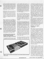
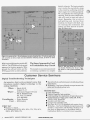
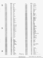
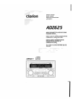
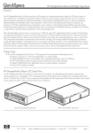
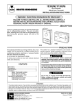
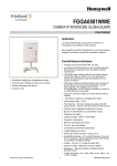
u
a
N FROM HEWLETT-PACKARD
E
JANUARY-FEBRUARY 1982
Functional
Analyzing
B y Jim Bechtold, Editor
Introduction
Functional analyzing usually provides the most direct and efficient
means of isolating a problem in an
electronic instrument. As another
term for logical troubleshooting,
functional analyzing is more appropriate and descriptive of the process
used in everyday bench service. Functional analyzing is antithetic to shotgun troubleshooting because functional analyzing involves analyzing
the unit in logical, sequential steps in
order to isolate the defective circuit,
rather than jumping around replacing components at random until the
problem goes away.
A bonus to this logical, sequential
diagnosis is that when you do discover
the cause of the problem, you acquire
a kernel of knowledge that is added to
your bank of experiences. Then, if a
similar problem occursagain, you can
draw upon your bank of past experiences and mentally bracket the problem area. Troubleshooting a n instrument by the shotgun method will
generally effect a repair, but you will
gain no knowledge of what caused the
trouble since you have only treated
the symptom - not diagnosed its
cause.
e
Functional Analyzing
Applied to a Real Life
The last issue of Bench Briefs described the theory of logical troubleshooting (see accompanying box
for a thumbnail description), and
Part No. 5952-0108
Figure 1. Mike Keenan, HP Technical Specialist, substitutes part of a good DVM into a faulty
unit as a form of haif-splitting.
showed how the step-by-step procedure could be used to isolate a problem
in the electrical charging system of an
automobile - a rather simple example. This article shows how these
same basic procedures are applied in
troubleshooting a complex electronic
instrument - a microprocessor controlled 6%-digit integrating digital
voltmeter (see Figure 1).
To document the procedure, I sat at
the bench with one of HewlettPackard's repair center technicians,
Technical Specialist Mike Keenan,
and observed him use the troubleshooting procedures we have been
discussing on an HP 3455A DVM. In
less than 15 minutes he isolated the
cause of a complete failure to a single
component.
was turned on, all annunciator lights
were illuminated and the display
remained blank. The DVM would not
respond to any switch settings. Before
Mike applied AC power, he removed
the covers and looked and smelled for
evidence of broken components or
heat. Everything seemed OK so Mike
connected the DVM power cord and
switched the unit on - in fact, he
switched it on and off several times.
The DVM repeatedly locked up at
turn-on just as the customer had indicated. Milking the front panel revealed only that all the lights worked
(except for the display, which was
blank).
IN THIS ISSUE
Functional Analyzing
The Customer Complained
that the DVM Locked Up at
Turn-On
Battery Cross-Reference
The first clue of trouble was the customer's complaint that when the unit
Service Notes
WWW.HPARCHIVE.COM
1982 Customer Training
Calendar
Logical Troubleshooting
The goal of logical troubleshooting
is to isolate the defective area in the
instrument in as few steps as possible. Getting started involves asking three questions:
1. What is the product supposed
to do? This may seem simpleminded but it will help you select
t h e required troubleshooting
equipment.
2. Does the product do what it was
designed to do? In other words, was
the customer trying to make the
instrument do something it was
not designed to do?
The next step was to see if anyoneelse
had experienced the same problem.
We could either ask other techs in the
area,or seeifthe problem waslistedin
the service manual - it was listed.
We had now completed several preliminary steps in the logical troubleshooting process (see accompanying box). We had:
- Verified the product was not doing
what it is supposed to do.
- Milked the insides and front panel
for clues.
- Looked to see if the problem
was common enough t o be
documented.
3. Have you or anyone else seen the
problem before? Or, is the symptom
listed in the service manual? Many
times there is a list of troubles and
probable causes in the manual’s
troubleshooting/service section.
The next logical step is to milk the
instrument for all symptoms available. Use your eyes, ears and nose.
Then you want to bracket the problem, which is simply a means of establishing broad limits around the
areas to be tested. This usually involves the next step which is halfsplitting.
Half-splitting involves making
checks a t the midpoints of the
Explanation. This DVM is electrically
and physically divided into two major
sections (with two major printed circuit boards). The inguard section,
which consists of the measuring circuitry, a controller, and power
supplies; and the outguard section,
which consists of most logic circuits
and their power supplies. The outguard circuits function as the internal
main controller, HP-IB interface, and
front panel interface of the instrument (see Figure 2).
remaining parts of the circuit that
have not yet been checkeduntil you
find the faulty portion of the
circuit.
In conjunction with half-splitting
you will want to use the information funnel approach; i.e., deciding
what type of check to make that is
most appropriate to the size of the
trouble brackets at a given time.
Performing the checks in this funnel sequence assures you wide coverage of trouble possibilities
initially, but with low precision.
Then, gradually, as you proceed to
localize the trouble, the checks become more precise.
The Manual Recommends a
Second Working DVM for
Effective Half-Splitting
Both the inguard and outguard sections have their own separate microprocessor controllers that handshake
back and forth. Both sections are interconnected through a single cable
that can be easily unplugged. The
manual troubleshooting procedure
recommends using a test cable (available from HP) and a second, functional 3455 DVM. The test cable is
The Service Manual’s
Troubleshooting Section
Helps Us Bracket the
Problem
The manual’s troubleshootingsection
told us to first verify that the raw
power supplies were working properly, Mike checked and the power
supplies were fine.
The next troubleshooting step told us
to half-split the instrument since
either of its two main sections could
hang up the turn-on sequence.
2
Figure 2. This complex DVM can be easily half-split where the inguard and wtguard Sections
are interconnected at pdnt
BENCH BRIEFS JANUARY-FEBRUARY 1982
8.
WWW.HPARCHiVE.COM
The inguard troubleshooting section
related that the turn-on fault could be
of course, would be
cally found the prob'agnosedits cause, he would
lar schematic that showed the -+loemel of knowledge to his
volt reference was derived from the
bank of experiences. The shotgun
method would only t r e a t the
symptom. In other words, the next
failure of this type that Mike came up
against, he still wouldn't know what
caused the problem.
We lifted a couple of diodes in the
cifcuit that could have been shorted,
and then umldered a transistor that
isolated a
n of the circuit* No
luck. Then Mike realized that 10volts
wm being drawn down to 0.6 volts,
which was almost ground. He looked
for and found Q34,a transistor that, if
shorted or leaky, would draw the 10volt reference to ground. Refer to Figure 6. When we lifted one leg on the
transistor, the voltage came right
digital voltmeter. The basic principle
was to isolate the one defective stage
in the circuit by confirming all of the
other stages were working properly.
We accomplished this through halfsplitting. And the same simple principle will work in most any type of
circuit. Remember, that as you are
half-splitting and moving those
brackets ever closer to the fault, you
are learning the instrument and
picking up those kernels of knowledge for future use.
a
Figure 4. A portion of the 1tl0-volt reference Circdtry. Note that th8 kt0 volts is used by the
A/D converter as well as input and auto-calibration switching circuits, all shown on other
schematics.
Mike replaced Q34 and turned the HP
3455 on. The DVM did not lock up and
appeared to function properly. Mike
pressed the self-test button and the
DVM passed with no other problems.
The Same Approach is Used
to TroubleshootAny Circuit
The example we coveredconcentrated
on isolating a problem in a complex
Figure 5. 033 waa Wabed full on and 034
was shorted. Therefore, the 10-volt +VREF
was drawn to near ground potential (0.6
volts).
Customer Service Seminars
Digital Troubleshooting Techniques
An intensive, short service-oriented course that
introduces modern
technology to the
analog repairman.
When - March22-25
August 10-13
Where - Instrument Support Division
690 E. Middlefield Rd.
Mt. View, CA 94042
(415) 969-0880
Coordinator - Debra Mazenko
Cost - $350/student
FIRST DAY
Analog vs. digital.
0 IC Technology: DCTL, RTL, DTL, CTL, TTL, ECL,
EECL, HTL, MOS, I2L.
1
4
BENCH BRIEFS JANUARY-FEBRUARY 1982
Specializedtools and techniques to troubleshoot these
technologies.
Workshop- four hours ofhands-on experimentswith
gates and troubleshooting tools.
SECOND DAY
P
0 Logicsymbo10gy.
I
Positive/Nerrative 1
UndersWd3ng the i'mplication of logic schematics.
Implementation of logic gates: AND,OR,NOR,
NAND, XOR, Wired-OR.
Decoders and their uses.
Comparators and their uses.
Flip-flops: R-S,D, J-K(standard and master-slave).
Workshop-four hours ofhands-on experimentswith
decoders, comparators and flip-flops. Students will
also have an opportunity to use modern tools to
troubleshoot faults in a printed circuit assembly.
WWW. HPARCHIVE.COM
B
THIRD DAY
a
0
containing flip-flops:
synchronous and ripple),
1-8,
ring counters.
Numberingsystems including binary, BCD, octal and
hexidecimal.
Introduction to binary math including half and full
adders.
Workshop- four hours of hands-on time building and
debugging counter circuits.
FOURTH DAY
ROMsPROM (masked, E and UV).
RAMs: bipolar and MOS (static and dynamic).
Typical failures and the troubleshooting difficulties
encountered with ROMs, PROMS and RAMs.
Typical memory addressing techniques.
Modern display technologies, their application and
common failure modes.
Introduction to the ROM-controlled device with
emphasis on methods used to fault isolate.
Workshop- four hoursofexperiments leading to the
building of a functioning strobed display device.
Logic Analyzers
A service-oriented course for calibration and
repair techniciansthat teaches application, circuit
theory and calibration.
When - April 5-8
Where - Colorado Springs Division
1900 Garden of the Gods Road
Colorado Springs, CO 80907
(303)598-1900
Coordinator - Mike Fredeen
Cost - $400/student
e
Hewlett-Packard, Colorado Springs Division, is offering
Service Training Seminars to customers on most all
models of Logic Analyzers. The courses are directed to
calibration and repair technicians and will teach application, circuit theory, calibration, and troubleshooting to
component-level repair. Attendees should have some
prior knowledge of logic and oscilloscope circuits.
The course objective is to teach front panel control operations, circuit theory, and learn the fundamental components used throughout the unit. Other areas covered are
the power supply, trigger recognition, data acquisition and
storage, and the display circuitry.
The student is guided through the three fundamental
areas of logic analyzers:
- Recognizing a trigger
- Storing the data
- DisDlavinP the data
Toward the end ofthe course, the instructor summarizesby
discussing overall troubleshooting from symptom to repair. The student is shown how to “ m i l k the front panel to
learn how failures affect the instrument’s behavior. From
the behavior patterns, the student learns how to isolate the
fault to a particular function within the instrument and
finally to the faulty component.
Ordering Information - All courses must be ordered
through your nearest HP Sales Office. If you desire additional information about a specific course, contact the
coordinator at the course location.
Battery Cross Reference
When selecting a replacement battery for your HP product, you may
notice that your manual will lisL only
a n HP part number, even though it
appears that this part is actually a
standard battery. Service personnel
often ask why only HP part numbers
are used.
It is a form of quality control. By
listing only HP part numbers we are
recommending that HP replacement
parts be used to ensure that original
performance of the product be retained. While some batteries used in
HP instruments are identical to those
that can be purchased a t a local electronics distributor, many batteries
are either specially manufactured to
HP specifications, not available over
the counter, or mechanically altered
to fit certain HP applications.
therefore a dead instrument; and HP
replacement parts are either not in
stock or will take a few days to obtain.
In these cases it may be worthwhile to
see if a substitute battery will work in
the circuit. Perhaps an HP battery
could be ordered and installed at some
later date.
To help you in these situations, here's
a list of batteries, their HP part numbers, and the manufacturer's name
and part number.
However, there may be situations
when you have a dead battery and
List of Battery Manufacturers
Number
Manufacturer
Number
Manufacturer
00029
01 394
01420
01447
01921
02000
02369
02413
02967
031 13
03551
03602
03941
04135
04304
04781
04910
Deac
Gates Energy Products
Burgess Inc.
Gould Inc.
RCA Corp. Solid State Div.
Muirhead Inst. Inc.
Gulton Battery Corp.
Clevite Corp. Burgess Batt. Div.
General Electric
Eppley Lab Inc.
Castall Inc.
Sonotone GSD Marathon Battery
Honeywell Inc.
Universal Products Inc.
Union Carbide Corp.
Ray-0-Vac Div. ESB Inc.
Union Supply Co.
05139
05296
05452
05469
05980
05987
06195
06450
06508
07230
07245
07371
08709
08781
08891
09593
09839
MacLeod & Handpol Inc.
RCA Corp. Electronic Comp.
Globe Battery Div. Globe-Union Inc.
Duracell InternationalInc.
Aglo La Pile S A R L
Saft
Varta Battery AG
Yuasa Denki KK
Japan Storage Battery Co.
Sonnenschein GMBH
Panasonic
Sanyo Electric Inc.
Panasonic
Catalyst Research Corp.
Power Conversion Inc.
Electrochem Industries Inc.
Plainview Electronics Corp.
HP P/N
1420-0001
1420-0001
1420-0001
1420-0002
142O-Oll2
1420-0002
1420-0003
1420-0@03
142@-@@@3
142o-aoo4
1420-0004
1420-@105
l420-00@6
142o-oao1
1420-0007
1421-0008
1420-0009
1420-0009
14~0-00I0
1420-0a11
1420-0a12
1420-0014
14PO-OEl4
1420-0@15
142@-OE15
1420-00l6
,142o-aa17
1420-0018
142o-oa11
1420-0019
1420-0119
1421-002a
l(20-0021
1420-0@21
1420-0022
1420-0022
1420-1022
1428-0022
1420-@023
1Q20-0023
1420-0024
1420-0025
1420-0025
1420-0026
1420-0026
1420-EO27
1*20-aa2a
1420-0029
1420-0030
1420-1@31
1420-@031
1420-0031
1420-0032
6
MFR
NUMBER^
01420
01304
01781
01420
04304
04701
01420
04304
05469
01420
a5469
05469
05469
02369
03602
03602
01 447
02967
05469
03682
03602
01447
02967
01447
04304
05469
05469
04304
05469
01447
02967
05469
04304
05469
01420
01921
04304
05469
04304
05469
04 304
04304
05469
01420
04304
05469
OS469
04304
01921
04314
04304
05469
05469
MFR
NUMBER
HP P/N
MFR P
N
I
142@-@033
142a-aO33
1420-1034
142@-0@35
US308
M762S
11109
HZ30wX
IY-350
n711
n210
142@-@@35
1420-DO36
1420-0037
1I
14 20
I31
1 42a
I3IO1
1 412 E
I1I9I
14 2 0
I4 0
1*
I4 1
I4 2
14 a
14 0
I4I4
I4I4
14 0
14 a
I4I¶
I4I7
14 a
I4 a I4I 11
nllso
IM-13X
MH6-3R
HRlC3R
MTR-233R-316469
,
WTUZ~M
nu-4200 zo-Pc20 MOD.
WSPEC. PlW23191
WPIN 23957
W401108
H41IiOOlRO1?6 1
WIR 235R-316469
H26042-5
n10-20n120
M403219
M4lEa84AA 1 7
nroo703-049
15-82251
1(01(12R1-2
MTR-236R-316469
IE-6301
14 0
I4I¶ I
14 0
1 4 '0
I4I9I
14
14
14
14
14
14
14
14
'8
'I
a
0
a
0
0
I¶IOI
I¶
I1
I¶
I2
I¶
I3
I¶I3I
I¶I3
I¶I3
01304
04304
M416
I4457
H362366
W30265l
MTR-132R
I4lR-135-R
MRMR
M316295 TIPE R M l R
a3941
05469
05469
OS469
05-9
05469
a3-1
139
05139
03113
ozeao
a144t
a4 sa4
os469
a3113
05w9
02 369
02813
02967
n
14 0
I¶is
M4IBOO4REOl
MRM-12-R
HE 233
MTR-233
HTYl
MVS-317
14
14
I7
I¶
OISI4
14 0
14 0
14 E
E5469
04304
H731
111 918
HE-9
WZR-9
14 0
14 0
14 0
nE-12
1 4I2
1 412
1 412
1 4I 1
I411
1 4I 2
1 42
1 4I 2
I4I2
I42
I¶7
I¶laI
I¶
10I
I¶ I
I6
I6
I6
I6
3I
14
14
I4I 2
WE-42M
HRM-42R
HM30
nrto.
482
MRM 4 0 1
WTR-I64
HE 216
nvSl02
H763
WE146X
IiIR146X
MIR-289
BENCH BRIEFS JANUARY-FEBRUARY 1982
Notes:
Replacement P/N
Status; H = actlwe
8
a
a
a
a
I4
I¶
I¶
14
¶
¶
I4I 2
6
1
1
IfI6 1
1
I6 81
16 4
I6 4
1 412
I
1 4I2
WWW.HPARCHIVE.COM
,
,
If 9
I1 0,
P/N
MC126
MTR126
I4504
MY15
@5¶8T
0144T
a4384
04304
WPX-1312
00YFR
04304
05469
04304
01420
04304
04781
a1447
01447
05469
0 1 447
02967
043a4
a0029
04304
04 101
01447
01420
01921
04304
05469
05469
01420
04304
05469
01420
I4505
n
n
n
nnn 1
NO-845-C
Me025
ITS671
nnm 15
niwa
WRMZU
tZOR20O
IIIP607Y
WPPSZ677R4
I20R200
n7.2112251
MT5637
IV-5511
IE302905
1302905
Ilk!-91
ns15
It402511
M
HP P/N
1420-0071
1420-0071
1420-00?3
LWO-OO~~
1428-0073
1420-0073
1420-0873
1420-W73
1420-0073
1420-0074
1420-0016
1420-0017
1420-0070
1420-0019
a
f
i
ie20-0ono
mo-noei
NP wu
ow20
04304
01921
04304
04 dw
wioi
04101
OSW9
05469
owni
*
1420-oonz
9
1420-OIOS
1420-0W3
1420-0004
1 4 20-0004
142o-O*Rs
142Q-SI86
14 20-0007
I @P)-0007
0
4
1*2a-.wm
1420-0890
1420-W9l
1420-0891
1420-0092
1 4 2 0-009 3
1420-0094
1420-8094
1420-0895
1420-0095
142e-0196
1420-0896
142o-oa91
1420-0017
14#0-0090
1420-0099
1420-0100
1420-0100
1420-0123
1120-8201
1420-020I
1420-0202
1420-0202
142s-om2
1420-OS03
1420-&03
04304
1420-8211
1420-0232
1420-0212
1420-0212
1420-0212
I 421-0212
J428-MlZ
1428481S
I4SFlS13
i*t+wa~
1*2a4&14
i*rwsi4
1
01447
054b9
02967
04 304
02967
04so4
01447
02967
02961
04304
02961
Ob500
02369
02967
07230
02 369
02967
01447
029C7
1*&0-025s
14&0-US4
1420-8&m
1*20-@&54
1428-00IS
l42o-oSss
1420-8zsS
1420-1255
1420-0&%
1425-8aS6
1
U
r
w
142CIw.
1428-1)11
04W4
84781
05-9
04384
04304
OSW9
85-9
04181
04-1
88-9
88469
82*?
Lt%7
u r 7
.sew
oin4
OiSW
a&%?
M
02961
M *2
07230
01m1
0 6 508
06500
02961
01447
02369
02369
02967
02967
84304
1*20-8&6S
I4.MzcI
1028-0264
142l-OZbS
142B-O)U
1420-026S
14S0-02b6
14SO-Ull
1428-0268
142ronr
1420-0110
04-
14SFWI1
1421-8212
1420-02t2
1420-I2?1
1420-0&73
W%?
O* as4
01420
M3W
lsTI-wI4
1115--WZl
m b l
1 ~ o - w ~
1420427b
lWS4216
1420-027l
14204S?O
142o-oZ?9
lU8-0219
1*20-0208
ll~o-OSeo
I4w-wol
1420-0282
1420-0881
142~-0p.4
14
14
H?Ol
8*
8805W6
1420-ONb
OlW4 R
08%l
8SM9
023W
UW7
1420-0226
1420-0221
1420-8227
1420-1220
Olaw
R
01447
02967
04304
01447
01447
02967
014Il
14
1*
a
UH?
H3W
Upw7
QH9
R
0s-9
04504
1
1420-u2*
1428-8&142+uw
1420-uw
1420-02w
1420.0225
04304
01487
843.4
O?rnl
lIS8-WSS
I
in20-w~
ll204224
0
0
0
01417
04304
1
14
14
14P1-(lt*
1428-U24
02967
02967
04301
02967
1
14za-8mz
0*304
S&%l
1
1
1
1
R
02367
05452
05452
04910
01394
02967
04 13S
02967
M%l
0ssIl7
81 3%
1
1
-
o(
OS 452
04304
05900
05907
01420
81420
1420-0206
1420-0207
1420-0207
HZO-0207
1420-0200
1420-0200
1420-8209
1420-0210
I42 0-021 0
14&8*NIZ
14SO+S43
1420-0243
14I8-UII
01447
04304
01447
1I)20-00(10
1410-0000
1420-8203
1420-02c4
1420-0205
1420-025s
1420-8&36
1420-0251
1420-02%3
1428-0230
1420-1230
1420-0239
1420-0240
Ob450
01441
04301
05469
06454
1
1420-~002
iwe-oonn
1420-0228
1420-0229
1420-0230
ieo-a231
1420-8232
1420-0213
1420-0233
1421-0134
YFR
N W R
1420-0204
1420-0205
1428-1205
1420-0206
1420-8287
1420-UO8
I 4 P 0-0289
Ism
014n
NSW
ObSH
84W
85-9
1420-0910
01 *&8
04304
O* 384
ISM9
OJ4b9
05452
05452
029b7
04 304
05452
vStatus; H = active
4420-8291
1420-0292
1420-0293
1428-0294
1420-0295
1420-0295
1420- 0296
1420-0297
142O-OP90
1420-0Z99
1420-9300
1420-0114
WWW. HPARCHIVE.COM
I
01391
01394
S&pw’I
02961
W9b7
R
M304
#Si?%
054b9
02967
82961
02961
04so4
07371
00109
W4SO
00181
014m1
02#1
01447
02967
08tOt
OtHl
05469
Ql447
02967
B1441
02967
01194
08702967
02967
04304
04101
05469
OOa9l
02967
OIS04
07371
09593
01394
00709
00109
07245
02967
LEADS
CUSTOMER SERVICE TRAINING CALENDAR FOR 1982
CONTENT
611.1615
Microcomputer
Development System
Model 64000 (Order
HP No. 59556290)
Scopes and Dkpbyr
Models 1740A, 1741A. 1742A.
1
7 (or&
~ nP~NO. 5955-4147)
1980 System (Order HP
NO. 5955-8046)
Automatic Test
3054A/C
System Verifiwtbn
dr Board Level Repsir
Circuit Test Systrm,
Model 3060A
DATES
TUITION
COORDINATOR
Colorado Springs Division
1900 Garden of the Gods R a d
Colorado Springs. CO 80907
Colorado Springs Division
S 400/student
Jerry Lopez
March 1-5
September 20-24
March 8-1 2
Colorado Sp-s
Dimon
S 3SO/rtWhnt
DickBrowne
Cobradb Springs Division
S 4M)/student
Di&Bro~le
February 22-23
Loveland Instrument Division
815 Fourteenth, S.W.
Lovchnd. CO 80537
Lovdsnd hatrumant M W n
S 250lstudent
Larry Carlaon
$2,50O/student
Sandy gltck
Lovetand Instrument Division
Sl,UO/rtudent
Sandy gltck
Instrument Support Division
690 E. Middlefield Road
Mountain View, CA 94042
Instrument Support Division
$
April 5-9
August 9-20
September 14-25
J m W y 4-15
pcbrcury 1-12
Wdr 1-1
April 12-23
May 3-14
June 6-17
July 12-23
A u g ~ 9-20
t
September 13-24
octbbsr 11-22
Novsmber $.19
a9 -~e=pbgto
LOCATION
z
-
9
2
Eastern WE#Regton
7121 SrcMlub D r k
FIanover, MD 21076
--
June 6-17
July 26 Au@ 6
Augurt 23 SepteRlber 1
J ~ W 11-15
Y
April 12-16
May 3-7
June 7-11
July 12-1 6
August 9-13
September 13-1 7
October 11-15
November 8-1 2
Deambu 6-10
DTS7O
Technology Training
Digital Troubleshooting
Techniques
Microproassor Troublwhootmg
Techniques
Digitel Troubleshooting
Devices
HPIB Fundamentals for
Service Technicians
9500D Automatic Test
Systems Maintenance
Sigul Andy&
Models 8566Al8568A
Spectrum Analyzers
141T/SSSSA/8553Bl8SSZB
Spectrum Analyzers
856SA/8569 Spectrum Analyzer
DSAILuec
5501A/5526A
Laser TransducerlMeasurement
SIC Fourier Systems
kk
8
~ o r e h1-1 2
A@ 12-23
May 2-14
June 6-17
July 12-23
August 9-20
September 9-20
October 11-22
Novcmber 8-19
November 29 December 10
-
March 22-25
August 10-13
350lstudent
Debra Mazenko
S 350/student
Debra Mazenko
Instrument Support Division
S 350lstudent
Debra Mazenko
Instrument Support Division
S 2OO/student
Debra Mazenko
Instrument Support Division
S 2,00O/student
Debra Mazenko
$ 700lstudent
Jim Boyei
June 21-25
Santa Rosa Division
1400 Fountain Grove Parkway
Santa Rosa,CA 95404
Santa Rosa Division
S 400/student
Jim Boyer
June 14-18
Santa Rosa Division
S 400/student
Jim Boyer
December 7-11
Santa Clara Division
5301 Stevens Creek Blvd.
Santa Clara, CA 95050
Santa Clara Division
Santa Clara Division
S 7001student
Lorraine h e &
S 700/student
S 700/student
Lorraine Pine&
Lorraine Pine&
January 18-21
Augwt 16-19
J O ~ U U11-13
Y
July 19-21
February 24
April 21
September 22
September 20 -October 1
January 25 - February 5
September 20 -October 1
March 1-5
July 6-16
BENCH BRIEFS JANUARY-FEBRUARY 1982
WWW. H PARCHIVE.COM
a
More on Logical Troubleshooting
'0
!
I
a
1
I
The last issue of Bench Briefs contained a demonstration problem that
was designed to prove the power of
half-splitting. The problem was to
take a standard deck of 52 playing
cards and remove one without looking
at it. Then determine which it is by
asking questions (i.e., making
measurements),
We solve the problem by halfsplitting where the probability of
finding the fault on one side of the
split or the other is 50%. Therefore,
the approach would be to repeatedly
split the cards into two groups and
meticulously zero in on the unknown
card. How many questionsare needed
to determine the selected card? The
first question can split between two
items. The second splits those into
two, for a total of four. The next question gets the total up to 8, the next 16,
etc. Thus, 6 questions can pick one
item out of a group of 64 (since
26 = 64).
k
!'
d
IS
IT A
WWW. H PARCHIVE.COM
JANUARY-FEBRUARY 1982 BENCH BRIEFS 9
1715A l%$GklO$CQF&
1715A-7. serials
d bkw. ihstrwims for
reptgcing Plast
transistors AlAlQ3 and
A2AlQ3 in vetwal attenuator boards.
17228 OSCIUOSCOPE
17226-4. Serials 2047A and below. tnstructions for
reptacing Plastic T-Pa& transistors AIAlQ3 and
A2AlQ3 in vertical attenuator boards.
Need Any Service
Notes?
They're free!
Here's the latest listing of Service
Notes. They recommend modifications to Hewlett-Packard instruments to increase reliability, improve performance, or extend their
usefulness.
Use the order form at the rear of
Bench Briefs to select the nobs that
1725A OSCILLOSCOPE
1725A-8. Serials 2047A and below. Instructions for
replacing Plastic T-Pack transistors AlAlQ3 and
A2AlQ3 in vertial attenuator boards.
3o&oABOARD TEST SYSTEM
306OA-0. Service note index.
30606-5A. Serials 18OlA00lOO and up, CCD Revision
1938. Modification of confirmation/configuratton
&agnostic (CCD) programs "digitl" and ".W802"
for proper 3455A operation during rweiver
30606-146. All serials. CCD modifWins for r
2027
3060A-15A. All serials. CCD revision 2027 modification
of "CNTRLR' program for proper operation during
the contrdler test.
306OA-168. All serials. CCD modifications for revision
2036.
306OA-18. Alf serials. InstrucWn for configuring the
device under test power supply interlock for all
power supply options.
308019-25. All serials. It4538
iMwhen opefatedin
=PwyL-TwE"rp
34656-4 An eercs)s. fawe d ~ m p ( K o b O ~ a t l 0for
ns
line voltage opttons
3476A/B DIGITAL NULTIHET~R
3476A-8 All serials Informahon for ethe
3476A A1 PC Assembly using the HP Biue Stnpe
Exchange Program
347655 At1 serials Information for exchangtng the
34768 A1 PC Assembly using the HP Btue Stnpe
Exchange Program
3496A SCANNER
3496A-3. All serials. Recommendreplacementof OUT
power supply relays 0490-1129 with date codes
8010 through 8037.
3497A DATA ACQUISlTtON/CONTROL UNil
3497A-9. All serials. Instructions for r m v i + the
option ROM when making a blue strlpe board
exchange of tha HP-16 mainframe w t g W controller board.
3N1A TRANSMlSSlON TEST SET
3551A-0. All serials. Service note index.
3551A-14. Serials 155OAO8320 anU below. Cure for
in h@ frequency and hgh
355554. MI ser
an intmoitfsntme
serials. Revision 2124 of the
nfirmatian/diagnosti software is
IIserials. Software BTL revision from 2014
# W C POWER METER
43253A. W a l s 1913A and Wow. Improved replacement cQU8l p a d meter installatiin kit (HP pn
00432aotrg.
432C-3A. Serials 1906A and below. Improved replacement dlgitai panel meter installation kit (HP pn
00432-60117).
All serials. Nottfiiation of BTLAPQ Update
Tape for revision 2117.
All systems with Option 100 HSDFT. Notifi-A-90.
cation of availability of DFT development/
production software tapes 03050-10101 and
030m10102.
306OA-31. All serials. Special instalktion instructions
for installing additional power supply in 34196A
power maiule in conjunction with optiMll00.
modes.
332SA SYNTHESZER/FUNCTION
GENERATOR
618C-15. All serials. Troubleshooting tip for the series
regulatorinthe-1000voltpOwersupply. Supersedes
618C-14 dated 5/81.
3325A-10. Serials 1748A-04251 and above; and
1746-04401 and above. Notification of new and improved PC board cunnectors and cables.
8208 SHF SIGNAL GENERATOR
6205f7. AU serials.Troubleshooting tip for the series
3335A SYNTHESUEWLEVEL GENERATOR
3335A-9. Serials 1640AQo270 and below. Recommendad replacement for the w M i n loop board
(A@ or the divider fitter board (A2).
13MA (78309A) DISPLAY
34OOA RMS VOLTMETER
1302A-4. Sefiils 1612A, 1643A, 1721A, and 1951A.
(Instruments with serials 2102A have the modification incorporated in production.) Modification kit
0 1 3 0 2 ~ and
5 01302.69506 (Option 012). M o 6
ification kit to improve reliability of the +158 volt
power supply.
3400A-11. Serials 1218A23475 and below. Rewrnmended transformer replacement kit 03400-68701
for older instruments.
13118 LARGE SCREEN DlSPLAY
34!56A DIGITAL VOLTMETER
3456A-5. Serials 2015A02970 and below. Recommended modificatin for AC relay protection.
3456A-6. All serials. List of 5OHz/6OHz line frequency
options vs crystal part numbers for the A30 lnguard
Logic PC Bard.
3456A-7. Serials below 2015A02161. Recommended
modificationto increase +33 volt reliability.
3456A-9. Serials below 2015A03071. Preferred ROM
replacement.
131153. Modification to prevent arcing of post accekwator lead in high humidityoperating conditions.
131154. All serials. Modificationto improve reliability
of the AB focus board.
37368 RF MODULE FOR 37308 MIWN
CONVERTER
3736&1. Serials 00141 and bebw. Improvement to
ensure fast lock-up in the tracking mode.
37378 RF MODULE FOR 37308 DOWN
CONVERTER
373751. Serials 00166 and below. Improvement to
ensure fast lock-up in the tracking mode.
373752. Serials OOlW and below. Change to overvottage protection to prevent damage to tensistor
A1 1Q4.
37388 RF MODULE FOR 37308 DOWN
CONVERTER
373852. Serials 00141 and below. Improvement to
ensure fast lock-up in the tracking mode.
3435A DlOrrAL VOLTMETER
3435A-7.Ail serials. List of user configured line voltage
options.
131152. All serials. Notification to check all 13118
Displays for the presence of grease in the P.A. lead
connector. The recommended grease is Dow
C%trniing5 compound, Hewlett-Packard part number
fsfmmO@.
358c)A/B/C SELECTtVE LEVEL METERS
3 W B f C - O . All serirds. S w v h note index.
3586A/B/C-2A. 3586A sends 1927A00231 and
below; 358W serials 1928AOO284 and below;
3586C serials 1929AOO195 and below. Recommended ROM retrofit for revision B software.
3586A/B/G6A. Ail serials. 3586A/B/C HP/IB verificat i program listing and operating instructions.
33
6 1 s SHF SIGNAL GENERATOR
regulatorinthe-1ooOvoltpowersupply. Supersedes
620816 dated 5/01,
3581NC WAVE ANALYZER
3581AG-7. All serials. Troubleshooting procedure to
test an intermittent metar circuit.
10 B E W EIPUEFS dANUARY-F€BRUARY 1982
WWW.HPARCHIVE.COM
37398 RF MODULE FOR 37308 DOWN
CONVElYKR
37398-1. Serials 00141 and below. lmprevement to
ensure fast lock-up in the tracking mode.
3779A/8 PRIMARY MULTIPLEX ANALYZER
3779A-22. Serials 2005U and b e h . Modifkaths to
softwareto remove various bugs and also to add the
diagnostic software package.
3779523. Serials 2005U and below. Modifications to
software to remove various bugs and also to add the
dragnostic software package.
t
4061A SEMICONDUCTOWCOMPONENT
TEST SYSTEM
4061A-1. Serials 2043Xx)lM and above. SofFuare revision from version E to version F.
4083A SWCHING CONTROLLER
4083A-2. Serials 1920500171 and below. Modification
to improve HP-IB control.
61296 DIGITAL VOLTAGE SOURCE
8!MA SPECTRUM ANALYZER
61296-4. Serials 1943A-00658 and beknnr. Modification to wfect output amplifier (A7) oseillatkn.
8566A-15. MI serials. Field installation procedure of
Option 650, Quasi-Peak Adapter Kit.
61%
&MA SPECTRUM ANALYZER
DIGITAL VOLTAGE SOURCE
6130C-4. Serials 1949A-01670 and below. Modification to correct output amplifier (A7) bscillation.
6131C DfOlTAL VOLTAGE SOURCE
4191A RF IMPEDANCE ANALYZER
4191A-2. All serials. Troubleshooling i n s t r u d i when
using the 16341A Lcgic Test Box.
4274A MULlbFREQUENCY LCR METER
OPTION 101 HWB INTERFACE
4274A-16. Serials 185RIo143 and below. Modification to prevent malfunction in option 101 HP-18
interiace.
4275A MULTI-FREQUENCY LCR METER
OpflOM 101 HPlB INTERFACE
4275A-13. EM& 1 8 4 W 1 1 1 and below. Modification to pnwsnt mdfunction in optin 101 HP-18
interface.
6131C-4. Sw@s 2114A-01160 and below. Modification to cwmct output amptifier (A7) oscillation.
Ilmwheo used
8WQA §PECtRUM ANALYZER
8569A-1.
6 9 4 a MULTIPROGRAMISER
6942A-2. Serials 2039A-1050 and below. Recommended front panel change to acmmodate round
LED indicators instead of the earlier rectangutar
LEDs.
6942A-3. Serials 2039A-01050 and M w . Modification to eliminate unwanted self-test looping.
6942A-4. Serials 2013A00321 and below. Recommended modification to eliminate the "cold start"
syndrome.
6-A
option 650.Ouasi-peek
8588A40. IF-OtSphy
below. Madkation to
with HP 8565oA Qum-
85696
Plotter
1
-
-A
SIGNAL QENERATOR
8656A-9. Swials 2124A and below. Fan replacement
proc%uwe.
.M
m
i to
MULTIPROGRAMMEREXTENDER
6943A-1. Seriars 2040A-00180 and W. Rscommended frm panel change to acaJmmolfae round
LED indicators instead of the earlier rectangular
LEDs.
spur offset from ou
of 99.SSW and 899.9993 MHz.
86561)-13. W a l s 2111A and bebw. W f i m t i o n to
reduce 140 MHz spur with an oufput frequency of 80
15%8A MILUOHMMETER
71008 STRIP CHART RECORDER
4328A-8. All serials. Installatoninstructions for the rechargeable battery Option 001.
7100510. Serials 2042A and 2043A. Recommended
replacement pen drive pulley and stop assembly.
865BA-14. Serials 2111A and below. Modification to
reduce spurs 17,37 and 42 W offset from output
frequenciesof . l to 123.5 MHz.
4961B PAIR IDENTIFIER AELO UNil
7101B STRIP CHART RECORDER
43MB 06 VOLT-AMMETER
430451. All eesie$. lnsfalkrtwn instwckwlfor the rechargeable battery Option 001.
MnZ.
8662A SYNTHESIZED SIGNAL GENERATOR
4961f3-4. All serials. Troubleshooting instructions for
the UART A4U4 (1820-1681).
7101f3-10. Serials 2042A and 2043A. Recommended
r
e
m pen drive pulley and stop assembly.
W l C WCROPROCESSOR EXERCISER
5001C1. Ad1 serials. *rating
inregarding
7 m A DRAFTING PLOTTER
theREAOYlinefromaunitun~rtestlofhe5001C.
7580A-1. All serials. Recommended pinchwheel
replacements.
S W A UNIVERSAL COUNTER
5316A-1. All serials. TmuMeshooti insmidions to
find Chart& C relay problem.
5340A MICROWAVE FREQUEWCY
COUNTER
534OA-20. serials 2116 and below. Modification to
prevent a random gating flaw (40 GHz indicated for
a lower frequency signal input).
5342A MICROWAVE FREQUENCY
COUNTER
5342A-27. Installation of extended dynamic range
Option bo3 retrpm kit part number 05342-60201.
5342A-28. Installation to Digital-bAnalog Conversion
(DAC) Option OW retrofit kit part number 0534260202.
53TQA UNIVERSAL TIME INTERVAL
COUNTER
53798-1I .&serials. Remunmendedaddition ta front
8018A DATA QENERATOR
8018A-3. SWi& 1828600825 and WOW. Modification
to the Ab memocy board and tow A12 memory
e m i o n buml to improve the timing & t i
for
the last bit signal (L) and signal N1023.
W7lA
- DTS-'lo SYS'IXM
95718-19. Software mid numbers 2100A00100 and
above. 91075D/E/F/J/K/L Somuare System, Rev.
2100.
37203A HPlB EXTENDER
37203A-6. All serials. Preferred replacement of IC
AlU55 (New part number 1820-0681).
64300 LOQiC ANALZYER
64390-1. Serials 1927A00051thsu 1927AOOO77. Modificetion to prevent @ic analysis traca errors.
8411A HARMONIC FREQUENCY
CONVERTER
841 1A-6. Serials 934-01805 and below. Recommended stripline replacement kit.
8411A-7. Serials 930and bebw. ! + a m m x M cable
replacement kit.
M
S427A WBRATION CONTROL SYSTEM
8443A-5. Serials 1821A and below. Low frequency
counter replacement kit HP part number 08443-
5501A LASER TRANSDUCER SYSTEM
867W SYNTHESlZED SIGNAL GENERATOR
8672A-7A All serials. New part number for AlCRl
leveling detector.
8405A VECTOR VOLTMETER
8405A-8. Serials 2014A and below. Recommended
"APC UNLOCKED' indicator light replacement.
8405A-9. Serials 2014A and below. IsolationAmplifier
transistor replacement to correct poor isolation between channels.
end checkout procedcae.
5427A-04. All serials. DAC Diagnostic Program
procedure.
8662A-4. Serials 2107A00680 and below. RF output
connector modification.
A TRACKING GENERATOR-COUfiER
60096.
85OOA/B MICROWAVE TEST SYSTEM
8500A-2A/85007A-l. All serials. Troubleshooting aids.
5501A-8. Recommended cleaning procedure for optical instruments.
5526A LASER MEASUREMEHT SYSTEM
5526A-6. R e c o m W cleaning procedure foroptical accessories.
8555A SPECTRUM ANALYZER
8555A-12A. All serials. Frequency response adjustment after replacement of input mixer assembiy HP
pfvt number 08555-60072.
6114A PRECISION POWER SOURCE
8565A SPECTRUM ANALYZER
6114A-1. Serials lfMgA-0229Q and bebw. Preferred
replacement fw the thumbwheel assembly.
8565A-7. Serials 2027A and below. Recommended
thud converter assembly replacement kit.
8565A-10. All serials. Improved frequency response
performance test.
8565A-11. All serials. Location of the input fuse to the
30V power supply.
6115A PRECISION POWER SOURCE
6115A-1. Serials 1937A-01OOO and bebw. Preferred
replacement for the thumbwheel assembly.
WWW. H PARCHIVE.COM
system verifcauon Btrws.
8500A-2N85W7A-f. All
formation on machii Iangu
bleshooting ads.
866338 MODUURBN
rams as trou-
N PLUG-IN
866338-1. Serials 185.1A and below. Modification to
prevent a remate grogramming controller hang-up.
JANUARY-FEBRUARY 1982 BENCH BRIEFS 11
Service Note Order Form
If you want service notes, please
check the appropriate boxes below
and return this form separately to
one of the following addresses.
Hewlett-Packard
1820 Embarcadero Road
Palo Alto, California 94303
For European customers (ONLY)
Hewlett-Packard
Central Mailing Dept.
P. 0. Box 529
Van Hueven Goedhartlaan 121
AMSTELVEEN-1134
Netherlands
197A-9
U 339A-8
U 3OWA-28
0 4328-3A
4191AL4?"
4274A-16
4275A-13
4304B-1
4328~~8
0
0
0
0
0
3496A-3
3497A-9
3551A-0
3551A-14
35558-4
0
0
0
0
0 496184
432CSA
618G15
62OB-17
13O2A-4
13118-2
3060A-29
3OWA-30
3OWA-31
3310A/B-7
3325A-10
0
0
0
0
0
3581A/G7
3588A/B/C-O
3586A/B/C-2A
3586A/B/C-6A
3586A/B/67
1311B-3
13118-4
1715A-7
17228-4
3335A-9
34OOA-11
3435A-7
3456A-5
3456A-6
0
0
0
0
0
3586A/B/C-8
37368-1
3737B-1
3737B-2
3738B-2
0 5342A-28
0 537OA-11
0 5427A-04
3456A-7
3456A-9
34658-4
3476A-6
3476B-5
0
0
0
0
0
3739B-1
3779A-22
37798-23
4061A-1
4083A-2
0 6114A-1
0 6115A-1
0 612%-4
0 613OC-4
0 6131G4
1m-B
-A-6;
3080A-5A
3OMA-148
-A-1
5A
3080A-16B
.
a
0 6942A-3
8568A-40
tf -A-1
0 6942A-4
0 6943A-1
0 71OOB-10
8656A-9
8656A-10
0 7101B-10
Q 758OA-1
0 8018A-3
0 8405A-8
0 8405A-9
0 500161
0 5316A-1
0 534OA-20
0 5342A-27
0
0
0
0
0 5501A-B
0 5526A-6
-A-1
1
WSA-12
8656A-13
8656A-14
867u-7A
W11A-6
8411A-7
8443A-5
85OOA-W
@5007A-1
Q 9571A-19
17501A-2AJ
17503A-2
37203A-6
d: 643W1
0 8555A-12A
0 8565A-7
0 8565A-10
0 8565A-11
el
'I
0 64503A-1
0 64507A-1
0 64509A-1
0 6494OA-1A
Q64940-2A
ipi 86633B-1
I
want to cut ofl the page.
I
.
Bulk Rate
I
U S . Postage
Sunnyvale, CA.
Permll No.
Volume 22 Num
Service information from
,
iubscription, send your request to thc
above address.
i
Reader comments or technical article
contributions are welcomed.
Please send them to the
Bench Briefs Editor.
Editor: Jim Bechtold
Hewlett-Packard
190 E. Middlefield Rd.
JANUARY-FEBRUARY 1982
"l.
WWW. H PARCHIVE.COM
,