1
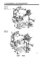
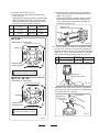
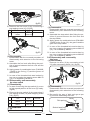
E. Remove the shock absorber bracket (31) by
unscrewing 4 pcs bolts (32) which fixing it.
(fig.20)
No.
32
Size
Tightening
torque
Remarks
Bolt M10X30,SW
53.9N・m
(39.8ft・lbf)
Apply Loctite
#221
Please match a position
of this lib with a head of
a bolt.
fig.23
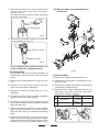
I. Remove the connecting rod (14) from crank
gear (101) with the pulley puller after removing the stop ring (17).
fig.20
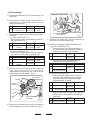
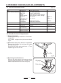
F. Remove the front cover (106) by shocking it
with the plastic hammer after unscrewing 8
pcs bolts (21) which fixing it. (fig.21)
No.
Size
Tightening
torque
Remarks
21
Socket Head Bolt
M8X25
24.5N・m
(18.1ft・lbf)
Apply Loctite
#242
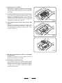
J. Remove the bearing (9) from the connecting
rod with the press after removing the stop
ring (16). (fig.24)
9
14
17
16
101
fig.24
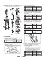
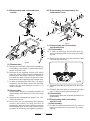
K. Remove the pinion drum (4) from the crank
case (1) with the press after removing the
stop ring (7). (fig.25)
fig.21
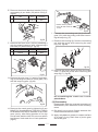
G. Remove the stop ring (11) which fixing bearing (10) through the hole of crank gear (101)
with the snap ring plier. (fig.22)
5
7
6
3
1
4
fig.25
Disassembling the crank case is completed above.
(2) Reassembly
fig.22
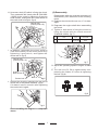
H. Remove the crank gear by tightening 2 pcs
M8x50 full threaded bolts (P/N:0091-10044)
to threaded holes which installed in the crank
gear evenly, after fitting position of the top
end of bolts and the ribs of front cover which
had three o’clock and nine o’clock positions.
(fig.23)
13
Reassemble with the reversed procedure of
disassembly with attention to the following
terms.
A. Be careful not to pinch fingers between the
crank case and the front cover.
B. Apply molybdenum grease to contact surface
of oil seal, O-ring, tooth face of pinion gear
and crank gear.