1
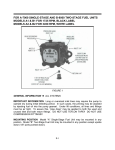
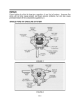
CAUTION
Pressurized or gravity feed installations must not exceed 10 P.S.I. on
inlet line or return line at the pump. A pressure greater than 10 P.S.I.
may cause damage to the shaft seal.
SOLENOID WIRING
DISCONNECT POWER SUPPLY BEFORE WIRING TO PREVENT
ELECTRICAL SHOCK OR EQUIPMENT DAMAGE. Lead wires on these
devices are long enough to reach the junction box on most burner
installations. Wire solenoid in parallel with burner motor (see Figure 3).
All electrical work should be done according to local and national codes.
(Solenoid 115V, 0.1A, 60 Hz.)
FIGURE 3
ONE-PIPE SYSTEM
DO NOT INSTALL BY-PASS PLUG! Connect inlet line to pump inlet.
Start burner. Arrange primary burner control for continuous operation
during purging. Open easy flow bleed valve 1 turn CCW. Bleed unit until
all air bubbles disappear -- HURRIED BLEEDING WILL IMPAIR
EFFICIENT OPERATION OF UNIT. Tighten easy flow bleed valve
securely (Figure 4). For additional information, see Single-Pipe
Installation Section, page III-1 of this manual.
The SUNTEC MODEL “A” - 70 FUEL UNIT may be installed ONE-PIPE
with gravity feed or lift.
The maximum allowable lift is 8 feet (see Figure 4).
IMPORTANT: One-pipe installations must be absolutely airtight or leaks
or loss of prime may result. Bleed line and fuel unit completely. Bleed
for 15 seconds after last air is seen from easy flow to be certain
lines are air free.
L=Line Length in Feet
H=Head in Feet
Q=Firing Rate in GPH
3/8" Line L = 6-.75H
1/2" Line L = 6-.75H
.0086 Q
.00218 Q
If tank is above pump, change - to +. Fittings, valves, and filters will
reduce total length allowed.
II-3