1
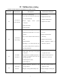
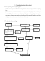
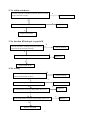
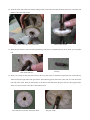
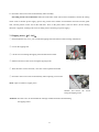
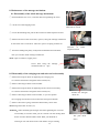
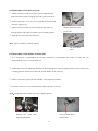
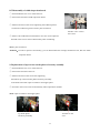
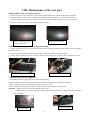
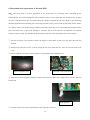
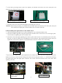
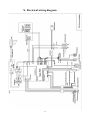
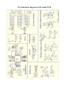
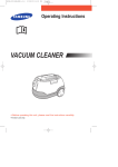
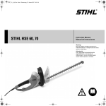
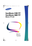
中国·厦门蒙发利科技有限公司
Xiamen Comfort Science & Technology Group Co., Ltd
EC-570
Maintenance Service Manual
Model:EC-570 Sereies
Voltage:220-240VAC
By Customer Service Department
厦门蒙发利科技公司客户服务中心
Maintenance Service Manual
Model
EC-570
Contents
I……Specifications ………………………………………………………2
II…..Appearance of the chair ……………………………………………3
III… Name and functions of components (remote controller)……………4
IV….Malfunction catalog…………………………………………………5
V…...Troubleshooting flow chart…………………………………………8
VI….Terminals on the main PCB ………………………………………13
VII…Maintenance of the back rest………………………………………14
VIII…..Maintenance of the seat part ……………………………………27
IX……Maintenance of the foot rest ……………………………………36
X…..Electrical wiring diagram …………………………………………39
XI…..Schematic diagram of the main PCB ……………………………40
XII…Contact us…………………………………………………………41
1
I. Specifications
Items
Specifications
Product Series
SMART MATE
Model NO.
EC-570B/ OG2800
Rated voltage
220~240V AC
Rated frequency
50Hz
Power consumption
150W
Rated time
15 minutes
Total time
60 minutes
When packing:1205×780×840(mm)
Dimensions
(Length × width × height)
When reclined:2000×750×700(mm)
When not reclined:1360×750×1150(mm)
N.W.: 65kg
Weight
G.W.: 83kg
Remote controller: 1 m
Line length
Power cord: 2.2 m
Temperature: 10~40 ℃
Usage condition
Humidity: 30~85 %RH
Temperature: 20~60 ℃
Storage condition
Humidity: 30~85 %RH
Safeguard
Over-current protector
2
II.Appearance of the chair
Remote controller
Pillow
Back pad
Holder of remote
controller
Arm rest
Seat pad
Foot rest
Side board
Wrench for extending foot rest
Front cover
of back rest
Rear cover of
back rest
Castor
Rear cover
under the seat
3
III.Name and functions of components (remote controller)
LCD display
Displays time and temperature
AIR key
Allows starting up
automatic charging program
THERAPY key
Allows starting
up automatic tapping program
SPOT key
Allows starting spot
massage just in the current
position. Position can be adjusted
by UP and DOWN
RELAX key
Allows starting
up automatic kneading program
KNEADING key
Full-back
mode, intensity can be adjusted.
key
Partial massage
taking the current position as the
center with height 16 cm. Center can
be adjusted by UP and DOWN
PARTIAL
TAPPING key
Full-back mode,
intensity and width can be adjusted.
DOWN key
Mechanical main unit
will run down by holding down it.
key
Full-back
mode of kneading and tapping,
intensity can be adjusted.
Rolling
ROLLING key
Heating
DUAL-ACTION
Full-back mode,
width can be adjusted.
UP key
Mechanical main unit will
run up by holding down it.
INTENSITY adjust key
Massaging intensity can be
adjusted at 3 levels. Only limited to
HEATING key
Allows starting
and stopping the heating in back
pad and foot rest
KNEADING, TAPPING, SWEDISH,
DUAL-ACTION, RELAX, THERAPY,
AIR
Keys for actuators
Allows adjusting the angle of
back rest and foot rest
WIDTH adjust key
Width between knead balls can be
adjusted at 3 levels. Only limited to
TAPPING, ROLLING
SEAT key
Allows starting
vibrators and charging gas-bags
in the seat pad.
key
Allows charging
gas-bags in the foot rest. Intensity
can be adjusted at 3 levels
FEET
CALVES key
Allows starting
vibrators and charging gas-bags in
the calves rest. Intensity can be
adjusted at 3 levels
PAUSE key
All the action will be broken off
by this key
ON/OFF
Allows starting and stopping the
chair.
4
IV. Malfunction catalog
Common Trouble and processing Methods are listed as follow:
Serial NO.
Phenomenon
Description
Maintenance Methods
The LCD isn’t illuminating:
① Replace Fuse.
①Fuse melts (in the Power Source Box
or on the main PCB).
No Function
01
When Starting.
②Power
supply
circuit
② Replace Power Box.
③ Replace EMC Board.
poorly
④ Replace main PCB.
connected.
③EMC Board fails.
④main PCB fails.
The LCD is illuminating:
①Mechanical switch fails or it’s wire is
①Replace mechanical switch or
it's wire.
②Replace Stroke Photo-
opened.
②Up or Down Stroke Photo-electricity
electricity.
No function
02
③Replace the main PCB.
fails.
when starting.
③Main PCB fails.
④Width Inspection Board of
④Kneading is on without pressing any
PCB fails, replace it.
key when starting and no response by
pressing other keys.
No Width
03
switchover.
①The terminals of Width Inspection on
main PCB and wires are poorly
connected.
②The terminals of Width Inspection on
massage mechanical and wires are
poorly connected.
①&②Plug the terminal securely
or replace the wires.
③ Replace Width Inspection.
④ Replace the main PCB.
③ Width Inspection fails.
④ Main PCB fails.
①Height Inspection Terminal or wire
No Partial
poorly contacts.
①Plug the terminal securely or
replace the wires.
04
Function.
②Height Counting Subassembly fails.
②Replace Height Counting Sub
-assembly.
5
①Terminal or Wire Poorly Contacts.
②Down-stroke Photo-electricity
Subassembly Fails.
③Up-stroke Photo-electricity
05
①Plug the terminal securely or
replace the wires.
②Replace Down-Stroke Subassembly.
No Rolling.
Subassembly Fails.
④Rolling Motor Fails.
⑤Main PCB Fails.
③Replace Up-Stroke Subassembly.
④Replace Rolling Motor.
⑤Replace main PCB.
①The terminals on main PCB and
06
wires are poorly connected.
①Plug the terminal securely or
replace the wires.
No kneading.
②Kneading motor fails.
②Replace the kneading motor.
③Main PCB fails.
③Replace main PCB.
① The terminals on main PCB and
①Plug the terminal securely.
wires are poorly connected.
07
②Replace the tapping motor.
No tapping.
② Tapping motor fails.
③Replace main PCB.
③ Main PCB fails.
No response
when pressing
08
the keys on the
remote
①The terminals and wires are poorly
connected.
①Plug the terminal securely or
replace the wires.
②The PCB in the remote controller
②Replace the remote controller.
fails.
controller.
①The terminals of reclining actuator
①Plug the terminal securely.
Back rest cannot
and wires are poorly connected.
09
②Replace reclining actuator.
be reclined or
②The reclining actuator fails.
③Replace main PCB.
raised
③Main PCB fails.
①The terminals of foot rest actuator
①Plug the terminal securely.
and wires are poorly connected.
②Replace foot rest actuator.
Foot rest
10
cannot be raised
②The foot rest actuator fails.
or lowered.
③Main PCB fails.
6
③Replace main PCB.
①Print motors fail.
①Replace the print motor.
②The terminals and wires are poorly
②Plug the terminal securely or
No vibration by
11
the motors in the
connected or the wires fail.
replace the wires.
seat-pad.
③Main PCB fails.
③Replace main PCB.
①Print motors fail.
①Replace the print motor.
②The terminals and wires are poorly
②Plug the terminal securely or
No vibration by
12
the motors in the
connected or the wires fail.
replace the wires.
Foot Rest.
③Main PCB fails.
③Replace main PCB.
①The terminal of the snuffle valves and
①Plug the terminal securely.
wires are poorly connected.
②Replace the snuffle valves.
No gas charging
13
②The snuffle valves fail.
③Replace the inflator pump.
③The inflator pump fails.
④Replace main PCB.
in the seat-pad.
④Main PCB fails.
①The terminal of the snuffle valves and
wires are poorly connected.
①Plug the terminal securely.
②Replace the snuffle valves.
No gas charging
14
②The snuffle valves fail.
③Replace the inflator pump.
③The inflator pump fails.
④Replace main PCB.
in the foot rest.
④Main PCB fails.
①The terminal of the heating and main
PCB are poorly connected.
No heating in the
②The connectors of heating on the top
①Plug the terminal securely.
②Connect
the
connectors
securely.
15
back pad
of the back rest are poorly connected.
③Heating leaf fails.
③Replace the heating leaf.
④Replace main PCB.
④Main PCB fails.
①The terminal of the heating and main
No heating in the
PCB are poorly connected.
①Plug the terminal securely.
②Replace the heating leaf.
16
foot rest
②Heating leaf fails.
③Main PCB fails.
7
③Replace main PCB.
V. Troubleshooting flow chart
Notes for repairing chair or replacing parts:
①Make sure the power is OFF before tearing down the wires, moving terminals or replacing
parts.
②Semiconductors (such as IC and others) are very easy to be damaged by static, so when you
touch the PCB, please make sure your body is grounding (by wearing a girding static ring), or
your hands are touching with earthing grip (household electrical appliances putting to earth, such
as fridges, washers and so on) to release all static of the body.
1. No function when starting.
Is the LCD
illuminating?
Is the fuse melted?
N
Y
Are the terminals of Up
and
Down
Stroke
是
Subassembly
connected
securely?
Y
Replace fuse.
N
Is the power cord
否
open-circuit?
Y
Replace power
cord.
Connect
securely.
N
N
Y
Y
The switches of Up and Down
Stroke Subassembly fail or not?
The EMC Board
fails or not?
Replace
N
N
Is kneading on without pressing any
key when starting?
N
Width Inspection
Board fails or not?
否
Y
Replace Width
Inspection Board.
N
Replace main PCB.
8
Y
Replace it.
2. No width switchover.
N
Are the terminals of Width Inspection Board and main
PCB connected securely?
Connect securely.
Y
Y
Width Inspection Board fails or not?
Replace it.
N
Replace main PCB.
3. No function(fixed-spot or partial)
N
Are the terminals of Height Inspection Board
and main PCB connected securely?
Connect securely.
Y
Y
Height Inspection Subassembly fails or not?
Replace it.
N
Replace Main PCB.
4. No rolling
Are the terminals of rolling motor wire and
main PCB connected securely?
N
Y
Connect securely
Y
Rolling motor fails or not
Replace the motor
Y
N
Replace it
Up stroke Photo-electricity subassembly fails or not
N
Y
Down stroke Photo-electricity subassembly fails or not
N
Replace main PCB
9
Replace it
5. No kneading
N
Are the terminals of kneading motor wire and main
PCB connected securely?
Connect securely.
Y
Y
Kneading motor fails or not?
Replace the motor.
N
Width Inspection Board fails or not?
Y
Replace it.
N
Replace main PCB.
6. No tapping.
N
Are the terminals of tapping motor wire and main
PCB connected securely?
Connect securely.
Y
Y
Tapping motor fails or not?
Replace the motor.
N
Replace main PCB.
7. Remote controller doesn’t work.
N
Are the terminals of remote controller wire and
main PCB connected securely?
Connect securely.
Y
Y
The conductive rubber fails or not?
Replace it.
N
Replace the remote controller.
10
8. Actuator doesn’t work.
N
Are the terminals of
reclining actuator and main
PCB connected securely?
N
Connect
securely.
Are the terminals of foot rest
actuator and main PCB
connected securely?
Y
Connect
securely.
Y
The reclining actuator
fails or not?
Y
Replace it.
Y
The foot rest actuator
fails or not?
N
Replace it.
N
Replace main PCB.
9. No vibration.
Are the terminals of
print motors in the seat
pad and main PCB
connected securely?
Y
否
Are the connectors in
the middle of the wire
connected securely?
Y
N
Are the terminals of print
motors in the calves-rest
and main PCB connected
securely?
Connect
securely.
Connect
securely.
Y
N
Connect
securely.
Are the connectors in
the middle of the wire
connected securely?
Y
Print motor fails or not?
N
Y
Replace it.
Print motor fails or not?
N
N
Replace main PCB.
11
N
Connect
securely.
Y
Replace it
10. No gas charging.
Are the terminals of snuffle
valve for bags in the seat
pad
and
main
PCB
connected securely?
N
N
Are the terminals of snuffle
valve for bags in the Foot
Rest and main PCB
connected securely?
Connect
securely.
Y
Connect
securely.
Y
Y
Snuffle valve fails
or not?
Replace it.
Y
Snuffle valve fails or not?
N
Replace it.
N
Are the terminals of
inflator pump and main
PCB connected securely?
N
Connect
securely.
Are the terminals of inflator
pump and main PCB connected
securely?
Y
N
Connect
securely.
Y
Inflator pump fails or not?
Y
Replace
Inflator pump fails or not?
N
Y
Replace it.
N
Replace main PCB.
11. No Heating in the back pad and foot rest.
The power is supplied to the
heating leaf or not?
Y
The connectors of the
heating are connected
securely or not?
Y
Replace the heating leaf
N
N
Connect them securely.
The terminal of the heating leaf on the
main PCB is connected securely or not?
N
Connect it securely.
Y
Replace the main PCB
Common trouble about electric control and processing methods of EC-570B are mentioned above.
It is for indication only.
12
VI. Terminals on the main PCB
Terminal of remote
controller.
Terminal
vibrators
Terminal of width
inspection.
of
Terminal of Height
Inspection.
Terminal of up and
down stroke photoelectricity.
Terminal
of
snuffle valves.
Terminal
of
snuffle valves.
Terminal of the
foot rest actuator
12VDC voltage
input terminal.
Terminal of the
reclining actuator
Terminal
of
inflator pump.
23VAC voltage
input terminal.
Terminal of rolling,
kneading and tapping
motors.
24VDC voltage
input terminal.
13
Warning: please make sure the massage chair is POWER OFF before maintenance and repair.
As the voltage is 220-240VAC, please make sure the plug is removed from outlet for safety
before processing operations as follow.
VII. Maintenance of the back rest
1. Disassembly of the back pad
① You can find a zip of the back pad on the top of the back rest.
② Unzip, and disconnect the connector of heating leaf, then the back pad can be removed.
③ If it’s damaged, a new one should be replaced. If the heating leaf fails, you can replace it too.
④ Proceed in the reverse order of disassembly when replacing a new one.
Zip of the back pad
Connector of heating leaf
Heating leaf
2. Disassembly and replacement the rear cover of the back rest
If disfiguring damage or crack happened, you can proceed as follow:
① Find 4 pieces of screws fixing the rear cover.
② Slacken and remove them with a plus screwdriver.
③ Then the rear cover can be removed.
④ If it’s damaged, a new one should be replaced.
Screws tightening the rear cover
(4pcs)
Attention: Take care not to damage the rear cover to avoid bad external appearance. Proceed in the reverse order
of disassembly when assembling the rear cover.
14
3. Disassembly of the back rest
① Release the stopper at the bottom of back rest, turn down the back rest forward.
② Slacken and remove the screws fixing the rear cover of seat part. Pull out the rear cover. Disconnect the
connector of back rest on the main PCB. And slacken and remove the screw fix the ground wire.
Turn down the back rest forward
Screws fixing the rear cover of seat part
③ Remove split pin, draw out flat head rivet securing the link rod and Y-type joint with nipper pliers to separate
the reclining actuator from the back rest.
④ Raise the back rest to the upright position, then pull it up to separate the back rest.
Tool:nipper pliers
Flat head rivet securing the link
rod and Y-type joint
Raise the back rest to the
upright position
15
4. Disassembly and replacement of the front cover of the back rest
If disfiguring damage or crack happened, or the inside
cloth is damaged, you can proceed as follow:
① After disassembling the rear cover, you can find 6 pieces
of screws fastening the front cover to the back frame.
② Slacken and remove the screws with a plus screwdriver.
Screws tightening the front cover
③ Then the front cover can be removed.
④ You should proceed in the reverse order of above operation if replacement needed.
Tool: a plus screwdriver
The top screws
Separate the front cover from the frame
5. Disassembly of the electric filter of the motor
① Release the stopper at the bottom of back rest, turn down the back
rest forward. Disassemble the rear cover.
② You can find a box of the filter at the bottom of the massage mechanism.
Cable ties tightening
the wires
③ Cut the cable ties tightening the wires on the sheet-metal with wire cutters.
④ Slacken and remove the screws tightening the upper and lower cover of the box.
⑤ The PCB and lower cover are fixed to the sheet-metal
with 2 pieces of screws. Slacken and remove the screws.
16
Screws tightening the upper and
lower cover ST3*8 4PCS
⑥ If the PCB fails, cut the wires and cable ties tightening the wires, then
replace a new one. Then connect the wires and secure it with line insulators.
⑦ Proceed in the reverse order of disassembly when assembly.
Tool: a plus screwdriver
The PCB and lower cover are fixed
to the sheet-metal
6. Disassembly of mechanical main unit
Attention: This method can be applied when the rolling motor is OK.
If the rolling motor fails, you can refer to 7.2 mentioned below.
① Slacken and remove the screw bolts, 8 pieces, fixing the cross beam
on the guide rails with a plus screwdriver.
② Cut the cable ties around the box of electric filter, find the wires
of the kneading motor, rolling motor and height inspection,
remove the line insulators with nipper pliers, disconnect the wires.
Screw bolts fixing the cross
beam
Bear in mind the connection of the wires to avoid confusion.
( The wires with blue sleeve is connecting to kneading motor,
and the red to rolling motor)
③ Pull out the terminal of the width inspection, cut the cable ties
tightening the wire. Cut the wire leading to the electric filter with wire cutters.
④ Find the wires of the rolling motor, connect to the wiring terminal of
The cross beam is removed
24VDC (a little lower can be accepted) power supply. Turn on the power
to elevate the mechanical main unit, until it runs out of the guide rails.
⑤ Then you can do what you want to the mechanical main unit.
⑥ Proceed in the reverse order of disassembly when assembly.
Tools: a plus screwdriver, nipper pliers, wire cutters,
24VDC power supply
Close-end
17
7. Replacement of the kneading, tapping and rolling motors
Attention: The voltage of this massage chair is high and the motors are rotating in high speed, so make sure the
power is OFF before disassembly. For safety, you should remove plug from outlet.
7.1 Kneading motor(DC -24V)
① Disassemble the rear cover of the back rest, and find the belt
at top of the massage mechanism, then loosen the belt as shown
in the picture.
② Find the wire of kneading motor, and cut the cable ties
Loosened belt
tightening the wire with wire cutters.
③ Remove the line insulator covering the wires with nipper pliers, then disconnect the wires.
④ Find 4 pieces of screws fixing the kneading motor to the sheet-metal, slacken and remove the screws with a
plus screwdriver.
⑤ Replace a new one if it does work.
⑥ Proceed in the reverse order of disassembly when replacing a new one.
Tools: a plus screwdriver, nipper pliers
Disconnect the wires
ST5*12
Screws fixing the
kneading motor
Tools needed and the
kneading motor taken off
7.2 Rolling motor(DC -24V):
If the power of rolling motor is supplied from main PCB and the wires between main PCB and the rolling
motor are OK, but the rolling motor doesn’t run. In this situation, there must be something wrong with the rolling
motor or reduction box. You can follow the following instruction to replace them.
Tools: a plus screwdriver, minus screwdriver, nipper pliers, wire cutters, shifting spanner, inner hexagon
spanners, 24VDC power supply
1. First, disassemble the cover of back rest. You don’t need to disassemble the whole back rest from the seat part.
2. Slacken and remove the screw bolts and nuts fixing the cross beam on the guide rails with a plus screwdriver
18
and a spanner. Take away the cross beam.
3. Slacken and remove the screw bolts and nuts, on both sides, fixing the plastic blocks in the guide rails with a
plus screwdriver and a spanner. Take away the plastic blocks.
Disassemble the cross beam
Disassemble the plastic blocks
4. Cut the cable ties around the box of electric filter, find the wires of the kneading motor, rolling motor and
height inspection, remove the close-end wire connectors with nipper pliers, disconnect the wires. Bear in mind
the connection of the wires to avoid confusion. (The wires with blue sleeves is connecting to kneading motor,
and the red to rolling motor.) Pull out the terminal of the width inspection, cut the cable ties tightening the wires.
Cut the wire leading to the electric filter with wire cutters. Make sure that there is no resistance when we pull
out the mechanical main unit with wheels.
Close-end wire connectors
5. Slacken and remove the screw bolts fixing the cover of the rolling motor on the reduction box with a inner
hexagon spanner, then the cover can be removed.
6. Pry the L-shaped sheet-metals on the side of the rolling motor with a minus screwdriver, and take them out.
Screw bolts fixing the cover
Pry the L-shaped sheet-metals
19
L-shaped sheet-metal
7. Turn the motor shaft in counter clockwise direction, then the mechanism main unit will run up. When the
pinions on both side un-gear with the teeth bars, you can pull out the mechanism main unit. Lay a piece of clear
cloth on the working table then put it on.
Mechanism main unit
Rolling motor without cover
8. After taking out the mechanism main unit, pull out the wheel on the rolling motor side.
Pull out the wheel
9. Slacken and remove the screw bolts fixing the reduction box on the sheet-metal with a screwdriver. If they are
so tight that can not be slackened, you can follow the second picture below to increase the lever of force.
Screw bolts fixing the reduction box
Increase the lever of force
20
10. Slacken and remove the screws, 6 pieces, fixing the upper and lower cover of bearing block with a plus
screwdriver.
Screws fixing the upper cover
Screws fixing the lower cover
11. Then you can pull out the shaft subassembly though the sheet-metal as you can see in the following picture.
12. Slacken and remove the screw bolt and nut fixing the pinion on the shaft with a screwdriver and nipper pliers.
Pull out the shaft subassembly
Disassemble the pinion
13. Pull the pinion out of the shaft. Slacken and remove the screws fixing the inner side cover on the outer side
cover with a screwdriver.
Pull out the pinion
Screws fixing the inner side cover
21
14. Then the outer side of the box and the rolling motor can be removed. Pull the inner side cover to another side.
Remove the outer side washer.
Remove the outer side cover and motor
Remove the washer
15. Push the gear wheel to the inner side (the bearing side), then can find the flat key in the shaft, you can pull it
out.
Flat key
Pull out the flat key
16. Then you can tap out the gear wheel. Put on the new gear wheel, it should be surpass the hole of the flat key.
Take care that the right side of the gear wheel. The following picture shows the outer side, so it will face to the
free end of the shaft. Then put the flat key in the hole of the shaft. Push the gear wheel on the right position.
Then you can put on the outer side of the reduction box.
This side faces to the free end of the shaft
The gear inside
22
17. Proceed in the reverse order of disassembly when assembly.
One thing needs to be mentioned: When the mechanism main unit has been assembled, connect the rolling
motor wires to 24VDC power supply (power off), put the lower wheels of mechanism main unit into the guide
rails, and the pinions on the end of the teeth bars. Turn on the power then it will run down. (If the running
direction is opposite, exchange the wires of rolling motor connecting to power supply)
7.3 Tapping motor(DC -24V):
① Disassemble the rear cover, you can find the tapping belt at the bottom of the massage mechanism.
② Loosen the tapping belt.
③ Cut the wire connecting the tapping motor and the electric filter.
④ Slacken and remove the screws fixing the tapping motor.
Tapping belt.
⑤ Then the motor can be removed, a new one can be replaced if needed.
⑥ Proceed in the reverse order of disassembly when replacing a new motor.
Tools: a plus screwdriver, nipper pliers
Slacken and remove the screws
fixing the tapping motor
Attention: You don’t have to disassemble the massage mechanism before disassembling
the tapping motor.
23
8. Maintenance of the massage mechanism
8.1 Disassembly of the whole massage mechanism
① Disassemble the rear cover, cut all the cable ties tightening the wires.
② Cut the wire of the tapping motor.
Cable ties are cut off
③ Loosen the kneading belt, pull out the terminal of width inspection board.
④ Slacken and remove the screw bolts, 4 pieces, fixing the massage mechanism
on the frame with a screwdriver. There are 4 pieces of spring washers too.
⑤ Turn the kneading belt pulley to adjust the width between knead balls,
Terminal
of
width
inspection board
then you can take off the massage mechanism.
Tools: a plus screwdriver, nipper pliers
Screw bolts fixing the massage
mechanism M5*12 4pcs
8.2 Disassembly of the swinging arm and universal rod assembly
① Slacken the hexagon check nut tightening the swinging arm
to eccentric shaft with a hexagonal socket wrench(1/2).
② Remove the hexagon check nut and washer.
③ Slacken the hexagon check nut tightening the universal rod assembly
to eccentric shaft with a hexagonal socket wrench(1/2).
④ Remove the hexagon check nut and washer, so you can separate
Slacken the hexagon
check nut
the swinging arm and universal rod from the massage mechanism.
⑤ Remove the tension spring, and further disassembly can be done.
Tool: hexagonal socket wrench (1/2)
Attention:When slackening the hexagon check nut tightening the universal
rod assembly to eccentric shaft, you can’t loosen it for the rotating shaft.
So the eccentric shaft should be fixed. What you should do is
inserting an iron rod into the hole of the shaft to stop its rotating.
24
The parts taken
down
8.3 Disassembly of the universal rod
① Slacken and remove the screw bolts, 3 pieces, tightening the
sheet-metal to the plastic swinging arm with a plus screwdriver.
② Remove the plastic cover, so you can separate the universal rod
form the winging arm.
③ Slacken and remove the screw bolt fixing the universal rod
Slacken and remove the
screw bolts
to bearing block with a plus screwdriver and a shifting spanner.
④ Then the universal rod can be removed.
Tools: a plus screwdriver, shifting spanner
The parts taken
down
8.4 Disassembly of the holder of knead ball
① It is unnecessary to disassemble the massage mechanism to disassemble the holder of knead ball, just
disassemble the rear cover of the back rest.
② Slacken the screw bolt tightening the holder to the swinging arm with a hexagonal socket wrench (10 mm) and
a shifting spanner. Pull the screw bolt out, and the holder can be removed.
③ Remove the tension spring and a new holder can be replaced if needed.
④ Proceed in the reverse order of disassembly when replacing a new one.
Tools:hexagonal socket wrench (10 mm), a shifting spanner
Slacken the screw
tightening the holder
bolt
The parts taken down
and the tools
25
8.5 Disassembly of width inspection board
① Disassemble the rear cover of the back rest.
② Pull out the terminal of width inspection board.
③ Slacken and remove the screws tightening the width inspection
board to the reduction gear box with a plus screwdriver.
Slacken and remove
the screws
④ Remove the width detection board and a new one can be replaced.
Proceed in the reverse order of disassembly when assembling.
Tool: a plus screwdriver
Attention:In order to operate conveniently, you can disassemble the massage mechanism first, then the width
inspection board.
9. Replacement of up or down stroke photo-electricity assembly
① Disassemble the rear cover of the back rest.
② Pull out the terminal of the wire.
③ Slacken and remove the screw bolts tightening
the PCB of up or down stroke photo-electricity assembly
to the sheet-metal with a plus screwdriver and nipper pliers.
④ Proceed in the reverse order of disassembly when replacement needed.
Tools: a plus screwdriver and nipper pliers
Up stroke photoelectricity assembly
Terminal of the
wire
26
VIII. Maintenance of the seat part
1.Disassembly of the cover under the seat
①
②
③
④
Pull out the power cord, release the stopper at the bottom of back rest, turn down the back rest forward.
Slacken and remove the screws, 4 pieces, fastening panel switch and the cover with a plus screwdriver.
You can find 2 holes on the cover, slacken and remove the screws inside, then the cover can be removed.
Proceed in the reverse order of disassembly when assembly.
Screws fastening panel
switch and the cover
Screws fixing the cover
2. Disassembly and replacement of the panel switch
① After removing the cover, you can find the panel switch is fixing on the base plate with two screws. Slacken
and remove them.
② Cut the outlet of the panel switch with wire cutters if the panel switch needs replacement.
③ Take a new one, connect the wires, and cover them with close-end wire connector. At last, tighten the screws.
Screws fixing the panel switch
Cut the wires of the switch
3. Replacement of power supply fuse
①Turn OFF the power supply and remove the power cord plug.
②Turn the fuse holder in the counterclockwise direction with a finger nail or a minus screwdriver.
③Take out the fuse from the fuse holder and replace with a new one.
④Put in the holder and turn the fuse holder in the clockwise direction, then it will be fixed.
Attention:①Make sure to use a glass tube fuse(the same type).
②Make sure to turn “OFF” the power supply and remove the power cord plug of the main unit from
the receptacle.
Take out the holder
The fuse holder
27
4. Replacement of the wave filter
① After taking off the cover, slacken and remove
the screws fixing the wave filter PCB on the
base plate with a plus screwdriver.
② After disconnecting a wire of the failed PCB,
connect it to the new one immediately with a electric iron.
Until all the wire are transplanted to the new one.
Screws fixing the wave filter PCB
ST4.2*10 2PCS
③ At last, tighten the screws.
In-out wires
5. Replacement of the pinboard
① After taking off the cover, slacken and remove
the screws fixing pinboard on the
base plate with a plus screwdriver.
② Pull out the teminals on the PCB, bear in mind
the connection of the teminals to avoid confusion.
You can connect one teminal to a new PCB just
when it’s disconneted from the failed one.
Screws fixing the
ST4.2*10 2PCS
pinboard
③ At late, don’t forget to tighten the screws.
Terminals on the pinboard
28
6. Disassembly and replacement of the main PCB
Tips:The main PCB is of great importance in the control part of a massage chair. Controlled by the
microcomputer, the external equipment of the computer system is more stable than the control circuit. So when
one part is non-functional, first we should check the voltage is supplied by the main PCB or not. Reasoning
should be applied and check all the parts concerning the failure, then you may find out the reason for the failure.
As a matter of fact, you should find the problem of the chair, then repair it. It is inconsiderable to replace all the
parts concerned when on part fails, although it will have the job done. But lots of manpower and material
resources will be wasted. You should learn the principle of the chair, then will find the reason more quickly.
① Pull out the power cord connector, release the stopper at the bottom of back rest, turn down the back rest
forward.
② Slacken and remove the screws, 6 pieces, fixing the rear cover under the seat. And you can take out the rear
cover.
③ Bear in mind the connection of the teminals to avoid confusion.Then pull them out.
Screws fixing the cover
Terminals on the main PCB
④ Disconnet the PCB supporter locking the main PCB on the base plate with a nipper pliers, then the PCB can
be taken off.
PCB supporter
⑤ Proceed in the reverse order of disassembly when replacing a new one.
29
7. Disassembly and replacement of the air pump and air storage boxes
① Disassemble the rear cover under the seat. Pull out all the connectors of the air hoses coming from the air
feeding box. Pull out the terminals of the air pump and snuffle valves on the main PCB.
② Slancken and remove the screws fixing the air feeding box on the basic plastic box with a plus screwdriver.
Then you can take the whole box out.
Screws fixing the air feeding box
③ Slacken and remove the screws fixing the plastic panel that tightens the air hoses. Then take it away. There
is a rubber pad between the panel and upper cover of the air feeding box. Slacken and remove the screws,
11 pieces, fixing the upper cover on the lower cover of the air feeding box. Then you can take way the
upper cover.
Screws fixing the plastic panel
④
Screws fixing the upper cover
Disassemble the black belt fixing the air pump. Pull out the rubber supporters fixing the air pump
on the base plate with nipper pliers. Pull out the connector of gas hose connecting the inflator and snuffle
valves. Then the whole pump can be removed. Then the air pump can be replaced if needed.
Black belt fixing the air pump
Rubber supporters
30
⑤ If the white gas storage boxes need to be replaced, just slancken and remove the screw fixing then, and
disconnect the connectors of the air hoses.
Screw fixing the air storage boxes
Air storage boxes with air hoses
⑥ Proceed in the reverse order of the disassembly when replacing a new one.
Attention: When fixing the pump, you should insert the rubber poles into the hole of the base plate, then pull
them though with nipper pliers, then the rubber poles are locked in the hole.
8. Disassembly and replacement of the snuffle valves
① After disassembling the upper cover of the air feeding box, you can find the snuffle valves.
② Pull out the rubber supporters fixing the sheet-metal of snuffle valves on the lower cover with nipper pliers.
Cut the cable ties tightening the wire of snuffle valves.
③ Disconnect all the R-clamps tightening the air hoses, pull out the air hoses. You had better pull out one hose,
then put it on the new snuffle valves immediately to avoid confusion. Then assemble the R-clamps. Then you
should take out the rubber supporters, and assemble them on the new snuffle valves subassembly.
R-clamps
Snuffle valves subassembly
⑤If just one of the snuffle valves needs replacement, first slacken and remove the screws fixing the valve on the
holder, cut the wires, remove the iron clamp, pull out the air hose, then pull out the “ U ” sheet-metal connecting
two plastic pipe joints with nipper pliers. Then the valve can be removed. Proceed in the reverse order when
replacing a new one.
Screws fixing the valve
on the holder
“ U ” sheet-metal
31
9. Disassembly of the reclining actuator
① Raise the foot rest to the extreme position,then release the stopper at the bottom of back rest, turn down the
back rest forward.
② Romove split pin, draw out flat head rivet securing the reclining actuator on the U stay fork and remove the
flat head rivet.
③ Remove the guard cloth under the foot rest, then one end with a motor of the actuator can be found. Romove
split pin, draw out flat head rivet securing the reclining actuator on the base frame and remove the flat head
rivet. Take care not forget the bush ring.
Flat head rivet securing the reclining
actuator on the base frame
Flat head rivet securing the reclining
actuator on the U stay fork
④ Then two methods can be followed:
A:Cut the wire of the actuator, take a new one and cut the wire too. Then connect the wire of the new one, turn on
the power to check the connection is right or not. If not, exchange it. Then put on a line insulator and tighten it.
This method is faster, it is suitable for skillful maintenance men.
B:Remove the seat pad and wooden plate under it, cut the cable ties fixing the wire of the actuator, then pull out
the terminal. Proceed in the reverse order when replacing. Obviously, it is time-consuming.
Cable ties tightening the
wire of actuators
Pull out the terminal (with red sleeve )
⑤ Proceed in the reverse order of disassembly when assembly.
32
10. Disassembly of the foot rest actuator
① Raise the foot rest to the extreme position, then you can find one end of the actuator is fixing on the U stay
fork. There are two plastic bush rings in the hole.
② Romove split pin, draw out flat head rivet securing the foot rest actuator on the U stay fork and remove the flat
head rivet.
③ Disassemble and remove the whole backrest, then one end with a motor of the actuator can be found. Romove
split pin, draw out flat head rivet securing the foot rest actuator on the base frame and remove the flat head
rivet. Take care not forget the bush ring.
Flat head rivet securing the foot
rest actuator on the U stay fork
Flat head rivet securing the foot
rest actuator on the base frame
④ Then two methods can be followed:
A:Cut the wire of the actuator, take a new one and cut the wire too. Then connect the wire of the new one, turn
on the power to check the connection is right or not. If not, exchange the wires. Then put on a line insulator
and tighten it. This method is faster, it is suitable for the skillful maintenance men.
B:Cut the cable ties fixing the wire of the actuator, then pull out the terminal. Take a new one, connect the
terminals and tighten the cable ties.
⑤ Proceed in the reverse order of disassembly when assembly. Don’t forget the bush ring in both ends.
33
11. Disassembly and replacement of the seat pad
① Find the zip connecting the seat pad and the outer coating of the foot rest, then upzip.
② Raise the seat pad, you can find two gas hoses and a wire there.
Unzip
Raise the seat pad
③ Disconnet the gas hoses and pull out the terminal of the wire,then the seat pad can be removed.
④ Proceed in the reverse order of disassembly when replacing a new one.
⑤ If the outer coating needs replacement only, cut the cable tie tightening the zip after the seat pad is separated.
Then unzip and take off the outer coating. Don’t forget to tighten the cable tie after putting on the new outer
coating.
⑥ You can slacken and remove the screws fixing the wood board on the base frame if the board needs being
taken away.
Cut the cable tie
Slacken and remove the screws
fixing the wood board
12. Disassembly and replacement of the arm rest
① Find a hole in the rear side of the arm rest, then slacken and remove the screw bolt inside whit a plus
screwdriver.
② Push the arm rest forward, then it can be removed.
Screw bolt
Push the arm rest
forward
③ Lock the sheet-metal in the front side to the hole of the side board
when replacing a new one. Then tighten the screw bolt.
34
13. Disassembly of the side board
① Disassenmle the whole backrest and the
seat pad(including the wood board).
② Find 4 pieces of nuts tightening the side board
to the base frame, then slacken and remove them
with a shifting spanner. There are 4 pieces of plain
washers under the nuts too.
Slacken and remove the nuts
③ Remove the cover under the seat, then you can
find a piece of screw fixing the side board to
the iron tube beside the castor. Slacken and remove the screw.
If it is not easy to operate, you should take away the base plate.
④ If the inside and outside board need being separated, slacken
and remove the screws tightening them. You can find the screws
in the holes on the inside board. You can do what is needed
after separating them.
Screw fixing the side
board to the iron tube
⑤ There is a mechanical control system of the foot rest in the right side board. After disassembling the whole
side board, a steel cable is still linking the board and seat part. If one part of the control system fails, you can
disassemble the side board and handle the problem.
Mechanical control system
Outside board taken apart
14. Replacement of the remote controller
① Remove the seat pad, disconnect the terminal of the remote controller.
② Slacken and remove the screws tightening the nylon clamps, then the remote controller can be removed.
③ Proceed in the reverse order of disassembly when replacing a new one.
Nylon clamp
Terminal of the remote controller
35
IX. Maintenance of the foot rest
1. Find the zip connecting the seat pad and the outer coating of the foot rest, then upzip.
Zipper
2. Slacken and remove the screw bolts and nuts fixing the foot rest to the base frame with shifting spanner and
inner hexagon spanner. As you can see, the iron cable and gas hose are still connecting to the seat part. If the
outer coating needs replacement, the gas hoses should be disconnected from the joints under the seat. Take
care not to lose the sleeves with different color.
Joints connecting the
hoses under the seat
Slacken and remove the screw
bolts and nuts
gas
③ Slacken and remove the screws fixing the guard pad at the bottom of foot rest with a plus screwdriver. Then
the guard pads can be removed.
Screws fixing the guard pad
36
4. Find the zip on the outer coating, then unzip. There are 4 ropes inside the outer coating, untie them, then you
can take off the outer coating.
Unzip
Ropes on the foot rest
Ropes on the outer coating
5. Slacken and remove the screws fixing the rear cover of the foot rest, then the cover can be removed.
Screws fixing the rear cover
Rear cover taken down
6. You can find 4 pieces of screws fixing the front cover at the back of the side air bags. Slacken and remove them,
then the front cover can be removed.
Screws fixing the front cover
Screw fixing the front cover
7.You can find an air cylinder fixing on the foot rest.
Air cylinder
37
8. Slacken and remove the screws, 4 pieces, fixing the air cylinder on the iron tube. Slacken the nut fixing the
screw bar on the sheet-metal. Slacken and remove the screws fixing the plastic setting. Then the air cylinder can
be replaced.
Screws fixing one end
Nuts fixing the screw bar
Nuts fixing plastic setting
9. If one of the air bag or gas hose is damaged, it should be replaced. The air bags are fixed on the front cover with
screws. Slacken and remove them. The joints of the gas hoses are tightened with cable ties. Disconnect the
connector, then you can replace the air bag.
Joints of the gas hoses
10. Proceed in the reverse order of disassembly when assembly.
Warning: As the voltage specification is 220~240VAC, please make sure the plug is removed from outlet before
processing operations above. Because of the complex structure, only professional maintenance man can be
approved to do the repair work to avoid damage to the product.
38
X. Electrical wiring diagram
39
XI. Schematic diagram of the main PCB
40
XII. Contact us
Please contact us if you have any questions:
The customer service department
Xiamen Comfort Science & Technology Co., Ltd,CSC
Address: 18#,LONGSHAN SOUTH ROAD XIAMEN 361009 CHINA
Tel: +86-592-5511161
Fax: +86-592-5564013
E-mail: [email protected]
Website: www.easepal.com.cn
41