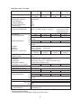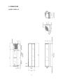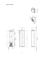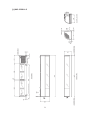
1
NO.
S041-789
ISSUED: OCT. 26, 2009
REVISED: JAN. 28, 2014
HOSHIZAKI
COUNTER SHOWCASE
MODEL
HNC-120BA-L/R-S
HNC-150BA-L/R-S
HNC-180BA-L/R-S
HNC-210BA-L/R-S
SERVICE MANUAL
IMPORTANT
Only qualified service technicians should install, service or maintain the
product. No service or maintenance should be undertaken until the technician
has thoroughly read this Service Manual. Failure to service and maintain
the equipment in accordance with this manual may adversely affect safety,
performance, and warranty coverage.
Hoshizaki provides this manual primarily to assist qualified service technicians in the
maintenance and service of the product.
Should the reader have any questions or concerns which have not been satisfactorily
addressed, please call, write, or send an e-mail message to the Hoshizaki Technical
Support Department for assistance.
HOSHIZAKI AMERICA, INC.
618 Highway 74 South
Peachtree City, GA 30269
Attn: Hoshizaki Technical Support Department
Phone: 1-800-233-1940 Technical Support
(770) 487-2331
Fax:
1-800-843-1056
(770) 487-3360
E-mail: [email protected]
Web Site: www.hoshizaki.com
NOTE: To expedite assistance, all correspondence/communication MUST include the
following information:
• Model Number
• Serial Number
• Complete and detailed explanation of the problem.
IMPORTANT
This manual should be read carefully before the showcase is serviced or
maintenance operations are performed. Only qualified service technicians
should install, service, and maintain the showcase. Read the warnings contained
in this booklet carefully as they give important information regarding safety.
Please retain this booklet for any further reference that may be necessary.
CONTENTS
PAGE
1. SAFETY INSTRUCTIONS ---------------------------------------------------------------------------- 1
2. MODEL NAME ------------------------------------------------------------------------------------------- 3
3. OPERATING INSTRUCTIONS ---------------------------------------------------------------------- 4
4. SPECIFICATIONS -------------------------------------------------------------------------------------- 5
5. DIMENSIONS -------------------------------------------------------------------------------------------- 7
[a] HNC-120BA-L-S ------------------------------------------------------------------------------------ 7
[b] HNC-120BA-R-S ------------------------------------------------------------------------------------ 8
[c] HNC-150BA-L-S ------------------------------------------------------------------------------------ 9
[d] HNC-150BA-R-S ---------------------------------------------------------------------------------- 10
[e] HNC-180BA-L-S -----------------------------------------------------------------------------------11
[f] HNC-180BA-R-S ---------------------------------------------------------------------------------- 12
[g] HNC-210BA-L-S ---------------------------------------------------------------------------------- 13
[h] HNC-210BA-R-S ---------------------------------------------------------------------------------- 14
6. REFRIGERATION CIRCUIT ----------------------------------------------------------------------- 15
7. WIRING DIAGRAM ----------------------------------------------------------------------------------- 16
8. CONSTRUCTION------------------------------------------------------------------------------------- 18
9. REMOVAL AND REPLACEMENT ---------------------------------------------------------------- 19
[a] SIDE COVER -------------------------------------------------------------------------------------- 19
[b] TOP COVER --------------------------------------------------------------------------------------- 19
[c] FRONT GLASS ----------------------------------------------------------------------------------- 19
[d] SIDE FRAME -------------------------------------------------------------------------------------- 20
[e] CENTER FRAME --------------------------------------------------------------------------------- 20
[f] HOLDER - EVAPORATOR PIPE ------------------------------------------------------------- 20
[g] UNIT ------------------------------------------------------------------------------------------------- 20
10. REFRIGERANT SERVICE INFORMATION --------------------------------------------------- 21
i
11. CONSTANT PRESSURE EXPANSION VALVE AND REFRIGERANT CHARGE ---- 22
[a] SPECIFICATIONS-------------------------------------------------------------------------------- 22
[b] FUNCTION ----------------------------------------------------------------------------------------- 22
[c] CONSTRUCTION -------------------------------------------------------------------------------- 22
[d] REPLACEMENT ---------------------------------------------------------------------------------- 23
12. SERVICE DIAGNOSIS ------------------------------------------------------------------------------ 24
ii
1. SAFETY INSTRUCTIONS
The following instructions contain important safety precautions and should be strictly
REVHUYHG7KHWHUPVXVHGKHUHDUHGH¿QHGDVIROORZV
WARNING 7KHUHLVDSRVVLELOLW\RIGHDWKRUVHULRXVLQMXU\IRUWKHVHUYLFHSHUVRQDQG
a third party or the user due to improper service operations or defects in
serviced products.
CAUTION
7KHUHLVDSRVVLELOLW\RILQMXU\IRUWKHVHUYLFHSHUVRQDQGDWKLUGSDUW\RUWKH
user or damage to their property* due to improper service operations or
defects in serviced products.
* The term “damage to their property” here refers to extensive damage to household
effects, houses and pets.
WARNING
$OZD\VDVNWKHXVHUWRNHHSFKLOGUHQDZD\IURPWKHZRUNDUHD7KH\PD\EHLQMXUHGE\
tools or disassembled products.
2. When there is no need to energize the unit during disassembly or cleaning, be sure to
unplug the unit or disconnect the main power supply before servicing the unit to prevent
electric shocks.
3. If the unit must be energized for inspection of the electric circuit, use rubber gloves to
avoid contact with any live parts resulting in electric shocks.
.HHSWKHIROORZLQJLQPLQGZKHQVHUYLFLQJWKHUHIULJHUDWLRQFLUFXLW
(1) Be sure to recover the refrigerant. Do not discharge it into the atmosphere. It will
affect the environment.
&KHFNIRUDQ\ÀDPHVLQWKHYLFLQLW\DQGHQVXUHJRRGYHQWLODWLRQ
,IWKHUHIULJHUDQWVKRXOGOHDNLQVHUYLFLQJLPPHGLDWHO\SXWRXWDQ\¿UHXVHGLQWKH
vicinity.
(4) When unbrazing the refrigeration circuit connections, check that the circuit is
completely evacuated. The refrigerant may produce a poisonous gas when coming
LQFRQWDFWZLWKDQRSHQÀDPH
(5) Do not braze in an enclosed room to prevent carbon monoxide poisoning.
(6) In case of a refrigerant leak, locate and repair the leaking part completely. Leaked
refrigerant may produce a poisonous gas when coming in contact with an open
ÀDPH
1
(7) Before servicing, check the surface temperature of the refrigeration circuit to
prevent a burn.
.HHSWKHIROORZLQJLQPLQGZKHQPDNLQJHOHFWULFDOFRQQHFWLRQV
(1) Check for proper grounding connections, and repair if necessary to prevent electric
shocks.
(2) Always use service parts intended for the applicable model for replacement
of defective parts. Use proper tools to secure the wiring. Otherwise abnormal
RSHUDWLRQRUWURXEOHPD\RFFXUDQGFDXVHHOHFWULFOHDNVRU¿UH
(3) Check for proper part installations, wiring conditions and soldered or solderless
WHUPLQDOFRQQHFWLRQVWRDYRLG¿UHKHDWRUHOHFWULFVKRFNV
(4) Be sure to replace damaged or deteriorated power cords and lead wires to prevent
¿UHKHDWRUHOHFWULFVKRFNV
(5) Cut-off lead wires must be bound using closed end connectors or the like, with their
closed ends up to avoid entrance of moisture that could lead to electric leaks or
¿UH
(6) After servicing, always use a megohmmeter (500V DC) to check for the insulation
resistance of at least 1 megohm between the live part (attachment plug) and the
dead metal part (grounding terminal).
(7) Do not service the electrical parts with wet hands to prevent electric shocks.
(8) The capacitors used for the compressor and other components may be under high
voltage and should be discharged properly before servicing.
CAUTION
$IWHUVHUYLFLQJIROORZWKHLQVWUXFWLRQVEHORZ
(1) Check for water leaks in the water supply and drain pipes to prevent damage to the
vicinity including household effects.
$OZD\VFKHFNWKHXQLWIRUSURSHURSHUDWLRQEHIRUH¿QLVKLQJVHUYLFHV
(3) Be sure to reassemble the parts completely. Loose assembly of such parts as
control box cover may cause entrance of vermins resulting in a short circuit
between terminals and possible ignition.
2
2. MODEL NAME
H NC - 120 B A - L/R - S
High Grade
Counter Showcase
Exterior
66WDLQOHVVVWHHO
:LGWKFP Unit Location
/8QLWRQOHIW
58QLWRQULJKW
Development Order
Starts from A
HA model
Unit on right
Unit on left
3
3. OPERATING INSTRUCTIONS
IMPORTANT
Hoshizaki Counter Showcase is intended for temporary food display.
&RQVWUXFWHGZLWKPXFKJODVVWKLVVKRZFDVHJLYHVUHODWLYHO\LQVXI¿FLHQWKHDW
insulation and poor cooling performance compared with refrigerators in general.
)RUVDIHDQGHI¿FLHQWRSHUDWLRQEHVXUHWRIROORZWKHLQVWUXFWLRQVEHORZ
1) Do not leave foods in the showcase after service hours, or they may dry or spoil. Foods
WKDWVKRXOGQRWGU\PXVWEHFRYHUHGRUZUDSSHGXSLQDSODVWLF¿OP
2) Store only pre-refrigerated items in the showcase. It takes longer for foods to cool in the
showcase than in a refrigerator.
3) Do not leave the doors open or open them too frequently. The interior temperature may
rise, resulting in food deterioration.
4) Do not pack the showcase with foods. The cooling performance may reduce, resulting in
food deterioration.
5) The showcase should not be exposed to direct sunlight or located next to ovens, grills
or other high heat producing equipment. The interior temperature may rise, resulting in
food deterioration.
6) The ambient temperature should not exceed 80°F (27°C). The cooling performance may
reduce, resulting in food deterioration.
7) The food mount can be used on either side. The food temperature is controllable by
turning over the food mount to change the distance from the interior bottom.
Normal condition
When food temperature is too low
For more intensive cooling
8) The maximum safe height for displaying food products is 3.5” (9 cm) above the interior
bottom. Food products should not be placed above this height as they may not remain
cold enough to avoid spoilage.
4
4. SPECIFICATIONS
Auxiliary code: C0 or earlier
MODEL
PRODUCT CODE
AC SUPPLY VOLTAGE
POWER SUPPLY CAPACITY
RATED AMPERAGE
STARTING AMPERAGE
ELECTRIC CONSUMPTION
POWER FACTOR
PULL DOWN TIME (10°C)
SATURATION TEMPERATURE
NET CAPACITY
EXTERIOR DIMENSIONS
HNC-120BA-L-S HNC-150BA-L-S
HNC-180BA-L-S HNC-210BA-L-S
-R-S
-R-S
-R-S
-R-S
L: S041
L: S043
L: S045
L: S047
R: S042
R: S044
R: S046
R: S048
1 Phase 115V
60Hz
0.47kVA (4.7A)
3.2A
13A
195W
56%
Approx. 30 min.(Ambient Temp. 27°C, No Load) Measured 20 mm above the
food mount(normal position)
Approx. 4°C(Ambient Temp. 27°C, No Load)
located at the interior bottom
center
42 L
1200 mm
(W)
(D) 345 mm
(H) 270 mm
57 L
1500 mm
72 L
1800 mm
87 L
2100 mm
845 mm
1145 mm
1445 mm
1745 mm
(W)
(D) 288 mm (bottom)
(H) 157 mm
Glass, ABS Plastic, PVC Plastic,
Stainless Steel
EXTERIOR
Glass, ABS Plastic, Stainless Steel
INTERIOR
Polyurethane Foam
INSULATION
L㸸D04762
L㸸D04764
L㸸D04766
L㸸D04768
DRAWING NO. (DIMENSIONS)
R㸸D04763
R㸸D04765
R㸸D04767
R㸸D04769
REFRIGERATION SYSTEM
Convection Cooling
DEFROST SYSTEM
None
COMPRESSOR
Hermetic 130W
Model CE56Y-1ZU
CONDENSER
Fin and Tube Type, Cooling Fan Motor x 1
EVAPORATOR
(UPPER) Bare Tube Type, (LOWER) Pipe on Sheet Type
REFRIGERANT CONTROL
Constant Pressure Expansion Valve
REFRIGERANT TYPE / CHARGE
R134a / 110 g
R134a / 130 g
R134a / 160 g
R134a / 180 g
ELECTRIC CIRCUIT PROTECTION Ground Fault Circuit Interrupter, Ground Wire
COMPRESSOR PROTECTION
Motor Protector
SLIDING DOOR
2 pcs.
4 pcs.
NET WEIGHT / GROSS WEIGHT
32 kg / 39 kg
37 kg / 46 kg
42 kg / 53 kg
47 kg / 60 kg
PACKAGE
Carton
SHIPPING DIMENSIONS
(W)
1300 mm
1600 mm
1900 mm
2200 mm
(D) 430 mm
(H) 473 mm
CERTIFICATION
To be NSF and UL certified
3 pcs.
4 pcs.
5 pcs.
6 pcs.
ACCESSORIES
FOOD MOUNT
VINYL HOSE 1 pc.
JOINT 2 pcs.
AMBIENT TEMP.
10 - 27°C
VOLTAGE VARIATION
Rated voltage ±10%
* The electrical specifications were determined at an ambient temperature of 27°C according to the electrical
appliance technical standards.
* The food temperature is controllable by turning over the food mounts.
INTERIOR DIMENSIONS
5
Auxiliary code: C1 or later
MODEL
PRODUCT CODE
AC SUPPLY VOLTAGE
POWER SUPPLY CAPACITY
RATED AMPERAGE
STARTING AMPERAGE
ELECTRIC CONSUMPTION
POWER FACTOR
PULL DOWN TIME (10°C)
SATURATION TEMPERATURE
NET CAPACITY
EXTERIOR DIMENSIONS
INTERIOR DIMENSIONS
(W)
(D)
(H)
(W)
(D)
(H)
EXTERIOR
INTERIOR
INSULATION
DRAWING NO. (DIMENSIONS)
REFRIGERATION SYSTEM
DEFROST SYSTEM
COMPRESSOR
CONDENSER
EVAPORATOR
REFRIGERANT CONTROL
REFRIGERANT TYPE / CHARGE
ELECTRIC CIRCUIT PROTECTION
COMPRESSOR PROTECTION
SLIDING DOOR
NET WEIGHT / GROSS WEIGHT
PACKAGE
SHIPPING DIMENSIONS
(W)
(D)
(H)
CERTIFICATION
ACCESSORIES
FOOD MOUNT
VINYL HOSE
JOINT
AMBIENT TEMP.
VOLTAGE VARIATION
HNC-120BA-L-S HNC-150BA-L-S
HNC-180BA-L-S HNC-210BA-L-S
-R-S
-R-S
-R-S
-R-S
L: s041
L: s043
L: s045
L: s041
R: S042
R: s044
R: s046
R: s042
1 Phase
115V
60Hz
0.44kVA (3.9A)
2.4A
15A
175W
63%
Approx. 30 min. (Ambient Temp. 27°C, No Load)
Measured 20mm above
Approx. 4°C (Ambient Temp. 27°C, No Load)
the food mount (normal
position) located at the
interior bottom center
42 L
57 L
72 L
87 L
1200 mm
1500 mm
1800 mm
2100 mm
345 mm
270 mm
845 mm
1145 mm
1445 mm
1745 mm
288 mm (bottom)
157 mm
Glass, ABS Plastic, PVC Plastic, Stainless Steel
Glass, ABS Plastic, Stainless Steel
Polyurethane Foam
L: D04762
L: D04764
L: D04766
L: D04768
R: D04763
R: D04765
R: D04767
R: D04769
Convection Cooling
None
Hermetic 110W
Model FL1152-PD
Fin and Tube Type, Cooling Fan Motor x 1
(UPPER) Bare Tube Type, (LOWER) Pipe on Sheet Type
Constant Pressure Expansion Valve
R134a / 95 g
R134a / 115 g
R134a / 145 g
R134a / 165 g
Ground Fault Circuit Interrupter, Ground Wire
Motor Protector
2 pcs.
4 pcs.
35 kg / 42 kg
40 kg / 49 kg
45 kg / 56 kg
50 kg / 63 kg
Carton
1300 mm
1600 mm
1900 mm
2200 mm
430mm
473 mm
To be NSF and UL certified
3 pcs.
4 pcs.
5 pcs.
6 pcs.
1 pc.
2 pcs.
10 - 27°C
Rated voltage ±10%
* The electrical specifications were determined at an ambient temperature of 27°C according to the electrical
appliance technical standards.
* The food temperature is controllable by turning over the food mounts.
6
5. DIMENSIONS
[a] HNC-120BA-L-S
7
[b] HNC-120BA-R-S
8
[c] HNC-150BA-L-S
9
[d] HNC-150BA-R-S
10
[e] HNC-180BA-L-S
11
[f] HNC-180BA-R-S
12
[g] HNC-210BA-L-S
13
[h] HNC-210BA-R-S
14
6. REFRIGERATION CIRCUIT
Expansion
Valve
Drier
Evaporator
(Upper)
Fan Motor
Condenser
Evaporator
(Lower)
Compressor
Heat Exchange
5HIULJHUDQW5D
15
7. WIRING DIAGRAM
Auxiliary code: C0 or earlier
Power Supply 1 phase 115V 60Hz
BK
W
BK
W
BU
CM
SR
SC
OL
FM
ELB
Compressor
Start Relay
Start Capacitor
Overload Relay
Fan Motor
Ground Fault Circuit Interrupter
16
Auxiliary code: C1 or later
BK
W
Power
Suppy 1 phase 115V 60Hz
2QYGT5WRRN[RJCUG8*\
BK
㧮㧷
W
㨃
GR / Y
㧳㧾㧛㨅
BK
㧮㧷
BU
W
㨃
BU
㧮㨁
CM
SR
SC
OL
FM
ELB
Compressor
Start Relay
Start Capacitor
Overload Relay
Fan Motor
Ground Fault Circuit Interrupter
17
8. CONSTRUCTION
Top Cover
Nameplate
Front Glass
Joint
Plug
Power Switch
(Ground Fault Interrupter)
Condenser
Center Frame
Air Filter
Slider
Louver
Sliding Glass Door
Food Mount
18
Hose
9. REMOVAL AND REPLACEMENT
CAUTION
1. Be sure to unplug the showcase before removing or replacing the parts.
2. Handle the glass parts with care.
[a] SIDE COVER
Remove the two machine screws at the
bottom, lift up the side cover, and unhook
the top.
[b] TOP COVER
Top Cover
Top Frame
Remove the sliding door and side cover.
7KHWRSFRYHULVKRRNHGDQG¿[HGRQWKH
top frame (aluminum).
2) Lift up and unhook the rear end of the top
cover.
3) When the rear part is lifted off, move it
forward to unhook and remove the front
part.
The top cover is tightly hooked on the top
frame and will not come off easily. Remove it
ZLWKFDUHWRDYRLGLQMXU\7RUHSODFHUHYHUVH
the removal procedure.
Fig. 1
[c] FRONT GLASS
Remove the sliding door, side cover and top
FRYHU/LIWWKHIURQWJODVVRIIWKHERWWRP¿W
The bottom and side interior of the front
glass is sealed with silicone sealant (black).
Be sure to re-seal it at replacement.
Top Frame
Front Glass
Fig. 2
19
[d] SIDE FRAME
Remove the sliding door, side cover and top cover. Unbind the wiring on the side frame.
Remove the two screws securing the top frame and the top of the side frame. Lift the side
IUDPHRIIWKHERWWRP¿W
[e] CENTER FRAME (Except HNC-120 type)
Remove the two flat head machine screws
(black) securing the center frame to the rear
and the two machine screws securing the
center frame to the top frame. Tilt the center
IUDPHDQGUHOHDVHLWIURPWKH¿W
Fig. 3
[f] HOLDER - EVAPORATOR PIPE
Holder Evaporator Pipe
Remove the truss head tapping screw (4 x 25)
from the bottom of the top frame. Take off the
center frame. Be careful with the evaporator
pipe. It will be released and hang down.
Remove the truss head tapping screw (4 x 10)
from the bottom of the top frame.
Truss Head Tapping
Screw 4 x 25
Evaporator Pipe
Truss Head Tapping
Screw 4 x 10
Fig. 4
Outlet Pipe
Expansion Valve
[g] UNIT
Remove the sliding door, side cover, top
cover, top frame and side frame. Take off
the compressor terminal cover and remove
the starter and motor protector. Uninsulate
the expansion valve and unbraze the outlet
pipe with a gas burner (see “11. CONSTANT
P R E S S U R E E X PA N S I O N VA LV E A N D
REFRIGERANT CHARGE”).
8QEUD]H WKH MRLQW LQGLFDWHG 5HPRYH WKH IRXU
machine screws securing the unit base. The
whole unit can be pulled out.
Joint
Fig. 5
20
10. REFRIGERANT SERVICE INFORMATION
1) Allowable Compressor Opening Time and Prevention of Lubricant Mixture [R134a]
The compressor must not be opened more than 30 minutes in replacement or service. Do
not mix lubricants of different compressors even if both are charged with R134a, except
when they uses the same lubricant.
2) Treatment for Refrigerant Leak [R134a]
If a refrigerant leak occurs in the low side of a showcase charged with R134a, air may
be drawn in. Even if the low side pressure is higher than the atmospheric pressure in
normal operation, a continuous refrigerant leak will eventually lower the low side pressure
below the atmospheric pressure and will cause air suction. Air contains a large amount of
moisture, and ester easily absorbs a lot of moisture. If a showcase charged with R134a
has possibly drawn in air, the drier must be replaced. Be sure to use a drier designed for
R134a.
3) Handling of Handy Flux [R134a]
5HSDLURIWKHUHIULJHUDQWFLUFXLWQHHGVEUD]LQJ,WLVQRSUREOHPWRXVHWKHVDPHKDQG\ÀX[
that has been used for the current refrigerants. However, its entrance into the refrigerant
circuit should be avoided as much as possible.
4) Oil for Processing of Copper Tubing [R134a]
When processing the copper tubing for service, wipe off oil, if any used, by using alcohol
or the like. Do not use too much oil and let it into the tubing, or wax contained in the oil will
clog the capillary tubing.
5) Service Parts for R134a
Some parts used for refrigerants other than R134a are similar to those for R134a. But
QHYHUXVHDQ\SDUWVXQOHVVWKH\DUHVSHFL¿HGIRU5DEHFDXVHWKHLUHQGXUDQFHDJDLQVW
the refrigerant have not been evaluated. Also, for R134a, do not use any parts that have
been used for other refrigerants. Otherwise, wax and chlorine remaining on the parts may
adversely affect R134a.
6) Replacement Copper Tubing [R134a]
The copper tubes currently in use are available for R134a. But do not use them if oily
inside. The residual oil in copper tubes should be as little as possible. (Low residual oil
type copper tubes are used in the shipped units.)
7) Evacuation, Vacuum Pump and Refrigerant Charge [R134a]
1HYHUDOORZWKHRLOLQWKHYDFXXPSXPSWRÀRZEDFNZDUG7KHYDFXXPOHYHODQGYDFXXP
pump may be the same as those for the current refrigerants. However, the rubber hose
21
and gauge manifold to be used for evacuation and refrigerant charge should be exclusively
for R134a.
8) Refrigerant Leak Check
Refrigerant leaks can be detected by charging the unit with a little refrigerant, raising the
pressure with nitrogen and using an electric detector. Do not use air or oxygen instead of
nitrogen for this purpose, or rise in pressure as well as in temperature may cause R134a to
suddenly react with oxygen and explode. Be sure to use nitrogen to prevent explosion.
11. CONSTANT PRESSURE EXPANSION VALVE AND REFRIGERANT
CHARGE
[a] SPECIFICATIONS
0RGHO
0DQXIDFWXUHU
3DUW1XPEHU
5HIULJHUDQW
$GMXVWPHQW5DQJH
3UHVVXUH5LVHE\$GMXVWLQJ6FUHZ
+<34+'
)XML.RNL
5D
03D
03DWXUQ
[b] FUNCTION
When the low side pressure drops, the Constant Pressure Expansion Valve opens and lets
WKHUHIULJHUDQWÀRZWRNHHSDFRQVWDQWSUHVVXUH
[c] CONSTRUCTION
IN (High Pressure)
$GMXVWLQJ
Screw
Cap
Needle Valve
OUT (Low Pressure)
Close
Open
DOWN
UP
Low Pressure
Working
Bar
$GMXVWLQJ
Spring
Diaphragm
Fig. 6
22
Inner Spring
[d] REPLACEMENT
WARNING
Always protect the valve body by using a damp cloth to prevent the valve from
overheating. Do not braze with the valve body exceeding 230°F (110°C).
IMPORTANT
Always install a new Drier every time the sealed refrigeration system is
opened. Do not replace the Drier until after all other repairs or replacement
have been made.
1) Recover the refrigerant (R134a) and store it in an approved container.
2) Remove the Insulation Cover and Cap from the Expansion Valve.
3) Remove the Expansion Valve by heating the Inlet and Outlet Pipes with a gas burner.
Wet Cloth
Evaporator
Burner
Burner
Drier
Fig. 7
23
12. SERVICE DIAGNOSIS
PROBLEM
POSSIBLE CAUSE
[1] Showcase will not 1. Ground fault circuit interrupter in
start.
OFF position.
2. Unplugged.
3. Supply voltage too low.
[2] Poor cooling
performance
[3] Dry foods
[4] Frosting
REMEDEY
1. Turn ON.
2. Plug in.
3. Plug into a separate receptacle of
115V ± 10%.
4. No power supply to the wall outlet. 4. Correct.
(Breaker or fuse blown out.)
5. Electrical circuit open or bad
5. Correct.
contacts.
6. Motor protector tripped.
6. Ventilate and reset fan motor.
1. Gas leaks.
1. Repair the leaks and recharge.
2. Fan motor defective.
2. Replace.
&RQGHQVHUDQGRUDLU¿OWHUFORJJHG 3. Clean.
4. Condenser air inlet blocked.
4 - 9. Instruct the user on
characteristics and proper use
5. Exposed to direct sunlight.
of the showcase.
6. Located next to a high heat
producing equipment.
7. Doors opened too frequently or left
open.
8. Packed with foods, or warm or hot
foods inside.
9. Ambient temperature exceeding 80
°F (27°C).
1. Foods have been stored from the 1 - 2. Instruct the user on
previous day.
characteristics and proper use
of the showcase.
2. Foods have been stored for a long
time.
1. [Exterior] Relative humidity
1 - 2. Instruct the user on
exceeding 60%.
characteristics and proper
use of the showcase. Wipe off
2. [Interior] Doors opened too
excessive frost with a soft cloth.
frequently or left open.
24