1
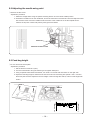
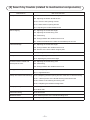
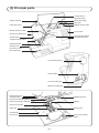
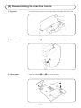
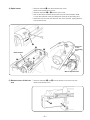
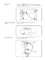
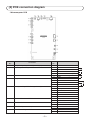
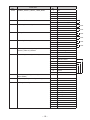
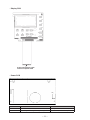
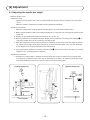
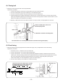
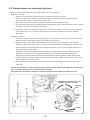
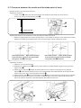
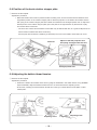
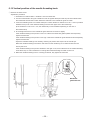
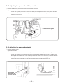
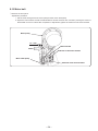
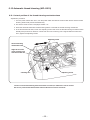
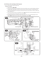
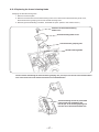
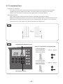
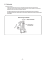
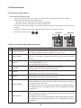
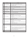
COMPUTER SEWING MACHINE
HZL-G Series
SERVICE Manual
6-2 Adjusting the needle entry point
○ Remove the face cover.
Adjustment procedure
1. Select the straight stitch using the pattern selecting button. Choose center needle position.
2. Assemble a needle #14 into the needle bar, loosen the setscrew in the eccentric collar and adjust the feed
bar eccentric collar so that the needle meets the center of the needle slot in the throat plate when it
reaches the top face of the throat plate by turning the hand wheel.
Setscrew
Feed bar eccentric collar
6-3 Feed dog height
○ Do not remove the throat plate.
1. Set the amount of feed to 0 (zero).
2. Turn the hand wheel to bring the feed dog to its highest dead point.
3. Using a tapered-head slotted screwdriver, turn shaft a on the left side and shaft b on the right side.
4. Adjust the feed dog height so that the front and rear ends of the feed dog are spaced 1.0±0.1 mm from
the throat plate surface. Adjust the rear end height of the feed dog with shaft a, and front end height with
shaft b.
Shaft a
Shaft b
Shaft a
Shaft b
– 14 –
1.0 ± 0.1 mm
Adjustment procedure
1.0 ± 0.1 mm
CONTENTS
[ 1] Specifications of HZL-G Series ............................................................ 1
[2] Search by trouble (related to mechanical components) ..................... 3
[3] Principal parts ........................................................................................ 4
[4] Disassembling the machine covers ..................................................... 5
[5] PCB connection diagram ...................................................................... 9
[6] Adjustment ........................................................................................... 13
6-1 Adjusting the needle bar height ...................................................................... 13
6-2 Adjusting the needle entry point ..................................................................... 14
6-3 Feed dog height ............................................................................................... 14
6-4 Timing belt ........................................................................................................ 15
6-5 Feed timing ....................................................................................................... 15
6-6 Timing between the needle and the hook ....................................................... 16
6-7 Clearance between the needle and the blade point of hook ......................... 17
6-8 Position of the hook rotation stopper plate .................................................... 18
6-9 Adjusting the bobbin thread tension .............................................................. 18
6-10 Adjusting the disk opening amount .............................................................. 19
6-10-1 Adjusting the tension release adjusting plate ................................... 19
6-10-2 Tension disk opening amount ............................................................ 19
6-10-3 Base tension opening amount ............................................................ 20
6-10-4 Adjusting the disk opening amount at the time of thread trimming (HZL-G210) ............................................................................................... 21
6-11 Adjusting the needle thread tension ............................................................. 21
6-12 Vertical position of the needle threading hook ............................................ 22
6-13 Adjusting the presser foot lifting switch ...................................................... 23
6-14 Adjusting the presser bar height .................................................................. 23
6-15 Motor belt ........................................................................................................ 24
6-16 Automatic thread trimming (HZL-G210) ....................................................... 25
6-16-1 Lateral position of the thread trimming mechanism base .......................... 25
6-16-2 Phase of the catching unit driving cam ....................................................... 26
6-16-3 Replacing the thread trimming blade .......................................................... 27
6-17 Longitudinal feed ........................................................................................... 28
6-18 Buttonhole ...................................................................................................... 29
6-19 Service mode ................................................................................................. 30
6-20-1 Service mode screen ................................................................................... 30
5-20-2 Service-mode items and descriptions ......................................................... 30
CAUTION:
Be sure to observe the following to protect against a fire, electrical shock, injury or damaged
components.
* Be sure to unplug the machine before disassembly, assembly or adjustment of the machine.
* Be sure to carefully prevent electric cords from being caught, coated surfaces from being
damaged as well as wrong wiring during assembly.
* Be sure to use the proper genuine parts when changing any of the machine parts.
[1] Specifications of HZL-G Series
(1) Power switch
・ 220-240V AC common to 50/60 Hz
・ 120V AC common to 60 Hz
(2) Power consumption
・ 65 W
(3) Dimensions and weight
・ Dimensions
・ Weight
Main unit: 445 (width) x 210 (depth) x 290.5 (height) (mm)
Case set: 510 (width) x 257 (depth) x 305 (height) (mm)
Main unit: G210 9.4 kg
G110 8.9 kg
(4) Revolution control
・ Slide style speed control
Straight stitch 80 〜 900 sti/min (SPM)
Pattern stitch
80 〜 750 sti/min (SPM)
Reverse stitch 80 〜 110 sti/min (SPM)
80 〜 900 sti/min (SPM) (when the speed controller is used)
Bobbin winding1500 〜 3000 sti/min (RPM)
Low-speed start 80 〜 110 sti/min (SPM) (approx. 1 second only when the power switch is turned ON)
・ Foot controller
Even when the foot controller is used, the speed control function by means of the slider is effective.
To stop the machine, either release the foot controller or press start/stop button.
The number of revolutions is controlled in the way same with the case of the slide speed control.
Thread trimming switch (Press heel side of foot controller.)
・ Safety control
When the motor shaft of the sewing machine is accidentally constrained, the power supply to the
motor is stopped within two seconds.
When the motor is overheated, the built in thermal switch stops the power to the motor.
Note that the machine can be restarted once the motor spontaneously cools down.
(5) Stop position
・ Upon finishing sewing, the machine stops according to the preset needle stop position (with its needle up or
down).
・ Upon finishing reverse stitching, the machine stops with its needle down.
・ In the case the machine is started with the presser foot lifting lever raised, the machine stops with its needle
up.
・ Needle moves down when the machine has preset so that the needle stops at its up position and needle up/
down button is pressed.
・ Needle moves up when the machine has preset so that the needle stops at its down position and needle up/
down button is pressed.
・ In the case of fault, the machine stops immediately (stop position varies).
(6) Zigzag width
・ Max. 7 mm depending on the pattern selected
––
(7) Amount of feed
・ The amount of feed is changed in increments of 0.2 mm by the stitch length adjusting dial.
(For the parallel parts of a buttonhole and satin stitches, the amount feed is changed in
increments of 0.1 mm.)
Default setting: 2.4 mm (for straight stitching)
(8) Pattern selection
・ Selection of three different kinds of patterns; Selection of number shifts
・ Segment type LCD
(9) Number of patterns
・ 180
(10) Automatic threading device
・ The hook section makes a turn by lowering the threading lever, and automatically returns to its original
position after completion of threading.
(11) Automatic lock stitch
When the backtacking switch is turned ON:
・ Straight stitch: Three stitches are sewn in normal direction and three stitches are sewn in reverse
direction at the beginning and end (the reverse switch is turned ON) of sewing.
Amount of feed: Same with the preset amount of feed
・ Other patterns: Zero-feed is inserted and one each stitch is sewn in the normal and reverse directions
at the beginning and end (the reverse switch is turned ON) of sewing.
Amount of feed: Fixed at 0.6 mm
(12) Buttonholing
Auto-return type full automatic buttonholing
Buttonholing size detection
––
[2] Search by trouble (related to mechanical components)
Phenomenon
Faulty thread tension
Item to be checked
6-8: Position of the hook rotation stopper plate
6-9: Adjusting the bobbin thread tension
6-10-2: Tension disk opening amount
6-10-3: Base tension opening amount
6-11: Adjusting the needle thread tension
Stitch skipping
6-1: Adjusting the needle bar height
6-2: Adjusting the needle entry point
6-5: Feed timing
6-6: Timing between the needle and the hook
6-7: Clearance between the needle and the blade point of hook
Thread breakage
6-1: Adjusting the needle bar height
6-6: Timing between the needle and the hook
6-8: Position of the hook rotation stopper plate
Hitch stitch
6-2: Adjusting the needle entry point
Faulty material feed
6-3: Feed dog height
6-14: Adjusting the presser bar height
Contact between needle and
throat plate or hook.
6-2: Adjusting the needle entry point
6-5: Feed timing
6-6: Timing between the needle and the hook
Faulty pattern shape
6-3: Feed dog height
6-17: Longitudinal feed
Faulty automatic thread trimming
6-10-4: Adjusting the disk opening amount at the time of thread trimming
6-16-1: Lateral position of the thread trimming mechanism base
6-16-2: Phase of the catching unit driving cam
6-16-3: Replacing the thread trimming blade
Faulty operating noise
6-4: Timing belt
6-15: Motor belt
Fault buttonholing
6-18: Buttonhole
Needle threader
6-12: Vertical position of the needle threading hook
Fails to start sewing
6-13: Adjusting the presser foot lifting switch
––
[3] Principal parts
Thread tension
adjustment dial
Speed controller
Spool cap (large)
Face plate cover
Bobbin winding shaft
Spool pin
Needle up/down button
LCD Screen
Presser foot lifting lever
Reverse stitch button
Operational buttons
Thread cutter
Thread trimming button
Start/stop button
Auxiliary bed
(accessory case)
Drop feed knob
Hand wheel (pulley)
Power switch
Foot-controller-jack
Machine-socket-inlet
Buttonholing lever
Threading lever
Presser foot releasing button
Presser foot holder setscrew
Needle setscrew
Needle
Presser foot holder
Presser foot
Feed dog
Throat plate
Hook cover
Hook cover release
button
––
[4] Disassembling the machine covers
1) Top cover
○ To remove the top cover, bow the hinge section of the right side of the cover.
2) Face cover
○ Remove setscrews 1 from the cover. Then, remove the cover.
1
3) Throat plate
○ Remove setscrews 2 and 3 from the throat plate.
Then remove the throat plate.
2
––
3
4) Spool cover
○ Remove setscrew 4 from the thread tension cover.
Remove the thread tension cover.
○ Remove setscrews 5 to 8 from the spool cover.
○ Pull out the cable of bobbin winder motor from the microcomputer PCB.
Loosen the setscrew of the grounding wire. Remove the grounding wire.
○ Remove the spool cover from the main unit of the machine, paying attention
to the base tension.
4
Setscrew
of the
grounding
wire
6
7
Base tension
5
8
Microcomputer PCB
5) Bottom cover of the free ○ Remove setscrews 9 and !0 from the bottom cover of the free arm.
Remove the bottom cover.
arm
9
!0
––
6) Bed cover
○ Remove setscrews !1 to !3 from the rubber cushion of the bed cover.
Remove setscrew !4 from the bed cover. Remove setscrews !5 and !6 from
the metal plate. Remove the bed cover.
!4
!1
!5
!6
!3
7) Upper cover of the free
arm
!2
○ Remove setscrew !7 from the upper cover of the free arm.
Remove the cover.
!7
8) Face plate cover
○ Remove setscrews !8 and !9 from the face plate cover.
Remove the face plate cover.
!8
!9
––
9) Front panel
○ Remove setscrews @0 and @1 from the front panel.
○ Put a thin screwdriver in the notch in the rising section under the arm and pry
off the front panel and hook A of the rear panel.
○ Opening the right side of the front panel in the direction of the arrow, tap Z
section with your hand to remove hook B located at the bed surface.
○ Lastly, remove hook C located at the lower side of the machine jaw.
○ Remove connectors for SUMI-card, start switch and LED lamp from the
microcomputer PCB when necessary.
@1
@0
Notch
Open
A
C
B
Z
10) Rear panel
○ Remove setscrews @2, @3 and @4 from the rear panel.
Remove the rear panel with the presser foot lifting lever raised.
@2
@3
@4
––
[5] PCB connection diagram
・ Microcomputer PCB
CN10
Connector
Terminal
Destination
No.
No.
CN1
ON_HAND_LED_CIRCUIT_BOARD_2 (Not installed)
1
5V
CN2
BOBBIN_WINDING_MOTOR
1
Bobbin winder switch
2
GND
3
Bobbin winder motor (+) (29V)
4
Bobbin winder motor (-)
CN3
OST SW
1
Presser foot lifting switch
2
GND
CN4
BH_SW
1
GND
2
BHR SW
3
BHS SW
4
5V
CN5
MAIN_SHAFT_DETECTION_CIRCUIT_BOARD
1
5V
2
Motor pulse
3
S1
4
S2
5
S3
6
GND
CN6
FLASH MEMORY INTERFACE
1
5V
6
GND
CN7
FOR FACTORY
2
GND
4
GND
CN8
RESERVE (Not installed)
1
5V
3
GND
CN9
CONTROLLER_SOCKET
1
GND
2
CONTROLLER
––
Connector
Destination
No.
CN10
POWER_SUPPLY_RELAY_LEAD_WIRE
CN11
MAIN MOTOR
CN12
THREAD_TRIMMING_STM
CN13
CN14
FEED_STM
NEEDLE_THROW_STM
CN15
THREAD_TRIMMING_STM_ORIGINAL
_POINT_CIRCUIT_BOARD
CN16
SW/SLIDE_VOLUME_CIRCUIT_BOARD
Terminal
No.
1
2
3
4
5
1
2
1
2
3
4
1
2
3
4
1
2
3
4
1
2
3
1
2
3
4
5
6
7
8
CN17
CN18
UNDER_ARM_LED_CIRCUIT_BOARD
(Not installed)
ON_HAND_LED_CIRCUIT_BOARD_1
CN19
PANEL_CIRCUIT_BOARD
– 10 –
9
1
2
1-3
4-7
8, 9
10, 11
12
13, 14
15, 16
17
18
19 - 22
23 - 26
27 - 29
30
30V
30V
NC
GND
GND
MAIN MOTOR (+) (29V)
MAIN MOTOR (-)
A
A
B
B
A
A
B
B
A
A
B
B
Detection signal
GND
LED G
LED R
Thread trimming/needle
up/down switch
Reverse stitch switch
S/S switch
5V
Speed control variable
resistor
GND
5V
NC
Switch strobe
5V
GND
LCD signal
3.3V PU
LCD signal
3.3V
GND
NC
Switch data
NC
GND
8.5Ω
8.5Ω
4.0Ω
4.0Ω
5.0Ω
5.0Ω
・ Display PCB
To be connected to CN19
of microcomputer PCB
・ Power PCB
CN2
CN1
Connector No.
Destination
CN1
POWER SW
CN2
POWER_SUPPLY_RELAY_LEAD_WIRE
– 11 –
Check
AC input
1-2PIN 29V, 4-5PIN GND(FG)
・ Connection block diagram
– 12 –
[6] Adjustment
6-1 Adjusting the needle bar height
○ Remove the face cover.
Adjustment value:
・ Distance from the bottom end of the pin inside needle bar surface to the top surface of the throat plate:
19 mm
・ When the needle is mounted, the needle eye tilts rightward by 2 degrees.
Adjustment procedure 1.
1. Select the straight stitch using the pattern selecting button. Choose center needle position.
2. Make a gauge needle by cutting a household needle HA x 1 to dimension A. Fit the gauge needle into the
3. Prepare an appropriate metal plate of thickness B. (A = 19 mm - B)
5. Place the metal plate on the throat plate. Move the needle bar up and down by hand to adjust so that the
needle bar.
4. Bring the needle bar to its lowest dead point. Slightly loosen needle bar connecting stud setscrew 1 as
long as the needle does not slip off from the connecting stud.
cut surface of the gauge needle aligns with the top surface of the metal plate. Then, turn the needle bar
by two degrees of an angle as illustrated in the sketch below.
6. Temporarily tighten needle bar connecting stud setscrew 1 and reconfirm that the needle bar is correctly
adjusted. Then, securely tighten the setscrew.
Adjustment procedure 2.
1. Assemble a household HA x 1 needle #14 into the needle bar, bring the needle bar to its highest dead
point. Move the needle bar in the same way as described in procedure 1 to adjust the needle bar height
so that the needle tip is spaced 15.5 mm from the top face of the throat plate.
[Lowest dead point]
[Highest dead point]
2°
19 mm
HA×1 #14
A
1
Gauge needle
Metal plate
15.5 mm
B
Throat plate
– 13 –
6-4 Timing belt
○ Remove the front panel and the microcomputer PCB.
Adjustment procedure
1. Loosen the setscrew in the idler mounting base and loosen the timing belt.
2. Turn the hand wheel to bring the needle bar to its lowest dead point.
3. Turn the hook driving shaft to bring the feed dog to its lowest dead point.
4. Carefully keeping the condition described in steps 2 and 3, set the timing belt on the hook driving shaft
pulley (by temporarily tightening the setscrew in the idler mounting base) so that the setscrew No. 2 in the
pulley is brought to just underside of the pulley.
5. Applying 1.96±0.29 N force to the idler by means of a spring scale, securely tighten the setscrew.
Push the middle part of the screw
with the spring scale.
1.96 ± 0.29 N
Setscrew of the idler mounting base
The setscrew No. 2 is located just underside of the hook driving shaft pulley.
6-5 Feed timing
○ After checking the feed dog height and the needle bar height, carry out adjustment of the feed timing.
Adjustment procedure
1. Assemble a HA x 1 needle #14 into the needle bar.
2. Loosen setscrew No. 2 in the hook driving shaft pulley.
3. Loosen setscrew No. 1 in the hook driving shaft pulley. Adjust the pulley so that the lower end of the
needle eye in the descending needle #14 is aligned with the top surface of the throat plate when the top
face of the descending feed dog is aligned with the top surface of the throat plate by turning the
hand wheel toward you. After adjustment, tighten the setscrew No. 2.
4. Turn the main shaft by one revolution to confirm the timing.
The lower end of the needle eye in needle
#14 aligns with or is 1 mm or less above
the top surface of the throat plate.
Setscrew No. 2
Top surface of the feed dog aligns
with the top surface of the throat plate.
Setscrew No. 1
– 15 –
6-6 Timing between the needle and the hook
○ Remove the throat plate, the bed cover and the bottom cover of the free arm.
Method for checking
1. Check to be sure that the needle entry point and needle bar height are correct.
2. Select the straight stitch. Select the right needle position by using the zigzag width adjusting dial.
3. Now, turn the hand wheel by hand to bring the needle bar to its lowest dead point.
(The needle entry point is shifted to the rightmost side.)
4. Turn the hand wheel further to gradually lift the needle bar until point C where the needle center is aligned
with the tip of blade point of the hook is reached.
5. At this time, check to be sure that the distance D from the tip of blade point of the hook to the upper end
of the needle eye is 3.1 to 3.3 mm. If this distance is not correctly provided, carry out the following
adjustment.
Adjustment procedure
1. Loosen the setscrew in the hook driving gear which is not visible from underside of the sewing machine
when the needle center aligns with the tip of blade point of the hook.
2. Select the straight stitch and the right needle position. Move the hook driving gear in the rotational
direction to adjust distance D of 3.1 to 3.3 mm is provided between the tip of blade point of the hook and
the upper end of the needle eye when the needle bar is lifted by 1.6 mm from the lowest dead point by
turning the hand wheel by hand.
At this time, the backlash between the hook driving gear and the gear on the hook side may change
therefore, be carried out with the visible setscrew temporarily tightened, while carefully observing the
hook driving gear in both the rotational direction and axial direction. Adjust the backlash to 0.2 to 0.7 mm
on the periphery of the rotating hook.
3. After confirming the timing between the needle and hook is correctly adjusted, securely tighten both
setscrews.
Caution: After adjustment of the hook, the hook race surface and the bobbin case holder may be stained with
dirt, oil or grease. Wipe them off with alcohol where necessary.
If those parts are left stained, chattering or thread slip-off noise of the bobbin case holder can occur.
Backlash on the periphery of the
rotating hook 0.2 to 0.7 mm
Rotating
hook
C
Hook
driving
gear
1.6 mm
depending on the location of the hook driving gear on the hook driving shaft. Adjustment should,
Distance D:3.1 to 3.3 mm
Larger
– 16 –
Smaller
Backlash
6-7 Clearance between the needle and the blade point of hook
○ Remove the face cover and the throat plate.
Adjustment procedure
1. Loosen screw 1. Adjust the clearance between the needle and the blade point of the hook to
0.02 to 0.07 mm by turning adjusting shaft 2.
2
1
0.02 to 0.07 mm
Adjusting the balance of the clearances at the right and left needle entry points
1. Select the zigzag pattern and set the zigzag width to 7 mm. Adjust the balance of the clearances provided
between the needle and the blade point of the hook at the right and left needle entry points.
Left needle position
Right needle position
If the clearance is larger at the right needle
entry point, shift 4 to the right.
Left needle position
Right needle position
If the clearance is larger at the left needle
entry point, shift 4 to the left.
Adjustment procedure
1. Select No. 2 of the service mode.
2. Gradually turn adjusting shaft 2 to find a position where the needle deviates slightly. Now, temporarily
tighten screw 1.
3. Slightly loosen setscrew 3. Adjust the lateral balance of the needle bar by slightly moving right-left
adjuster 4 while carefully listening to the noise produced when the needle deviates at the right and left
needle entry points. Then, securely tighten setscrew 3.
4. Additionally turn shaft 2 and securely tighten screw 1 at the position where the needle does not deviate.
5. Lightly tap P section with fingers. If you hear a needle deviation noise at the right and left needle entry
points, the optimum clearance is provided between the needle and the hook.
2
1
3
– 17 –
4
P section
6-8 Position of the hook rotation stopper plate
○ Remove the throat plate.
Adjustment procedure
1. When the bobbin case holder is placed inside the rotating hook, loosen the setscrew and determine the
longitudinal position of the rotation stopper plate so that the projection of the bobbin case holder and the
lateral position of the rotation stopper plate, press the plate in the right direction by the amount of play
leaf spring of the rotation stopper plate are located as illustrated in the enlarged partial view. To adjust the
and secure with the setscrew.
* The hook race surface and the bobbin case holder may be stained with dirt, oil or grease. Wipe them off
If those parts are left stained, chattering or thread slip-off noise of the bobbin case holder can occur.
with an alcohol-soaked cloth where necessary.
Setscrew
Adjust so that the projection and
leaf spring are aligned with this line.
Enlarged partial view
6-9 Adjusting the bobbin thread tension
○ Remove the throat plate.
Adjustment procedure
1. Position the bobbin case holder and a tension gauge as illustrated in the sketch below. Using SHAPPE
Span thread #60, adjust the bobbin thread tension to 0.13±0.02 N with the adjusting screw.
At this time, carefully prevent the bobbin thread from coming in contact with the throat plate or other
related parts.
Adjusting screw
– 18 –
Adjusting screw
6-10 Adjusting the disk opening amount
6-10-1 Adjusting the thread tension release adjusting plate
○ Remove the face cover, the thread tension cover and the spool cover.
Adjustment procedure
1. Raise the presser foot lifting lever.
2. Loosen the adjusting screw and adjust the thread tension release adjusting plate so that the top end of
claw of the opening arm aligns with the marker dot on the thread releasing arm.
Thread tension release adjusting plate
Thread releasing arm
Opening arm
Adjusting
screw
Align with the marker dot
6-10-2 Tension disk opening amount
○ Remove the face cover, thread tension cover
and the spool cover.
Adjustment procedure
1. Maximize the tension with the thread tension
adjustment dial. Raise the presser foot lifting lever.
2. Adjust the clearance between tension disks (A)
and (B) to 1 mm by turning the thread tension
float adjusting screw.
Disk B
Disk A
– 19 –
1 mm
6-10-3 Base tension opening amount
○ Remove the face cover, the thread tension cover and the spool cover.
Adjustment procedure
1. Raise the presser foot lifting lever.
2. Adjust the base tension opening amount to 1 mm by turning the base tension adjusting screw.
1 mm
Base tension
adjusting screw
Thread tension
disk float adjusting
screw
Tension disk float
adjusting screw
* The pretension disk float adjusting screw and the tension disk float adjusting screw can be
turned without loosening the nuts.
– 20 –
6-10-4 Adjusting the disk opening amount at the time of thread trimming (HZL-G210)
Adjustment procedure
1. Lower the presser foot lifting lever.
2. Select No. 9 (meaning: tension release) of the service mode.
3. Loosen the locknut. Turn the adjusting nut to adjust the retracting amount of the thread tension releasing
link plate so that the top end of claw of the opening arm is aligned with the marker dot on the thread
tension releasing arm.
4. At this time, check to be sure that the opening amounts of the pretension disk, thread tension disk and
base tension are same as those provided when the presser foot lifting lever is raised.
Locknut
Opening arm
Thread tension
releasing arm
Align with the
marker dot
Thread tension
releasing link plate
Adjusting nut
Caution: After adjustment of the opening amounts of each tension control part, lower the
presser foot lifting lever or return the thread tension releasing link plate to its home position to make
sure that those tension control parts are closed.
6-11 Adjusting the needle thread tension
○ Remove the thread tension controller cover.
Adjustment procedure
1. Raise the presser foot lifting lever.
2. Turn the thread tension adjustment dial to bring its "AUTO" section to the top.
4. Lower the presser foot lifting lever. Turn the adjusting nut to adjust the tension so that the tension gauge
gives a reading of 0.49 to 0.59 N.
Adjusting nut
– 21 –
1
7
2
6
5 4 3
8
3. Prepare SHAPPE Span thread #60 and a tension gauge. Thread the base tension and the tension disk.
0
6-12 Vertical position of the needle threading hook
○ Remove the frame cover.
Adjustment procedure
1. Assemble a household HA x 1 needle #11 into the needle bar.
2. Turn the hand wheel to bring the needle bar near its highest dead point and stop the hand wheel when
3. Lower the threading lever to its lowest dead point. Check whether a clearance of 0 to 0.1 mm is provided
the needle bar reaches the location where the setscrew in the needle bar guide is visible.
between the top end of the needle threading hook and the upper end of the needle eye.
(If the clearance is not 0 to 0.1 mm, the needle may not be threaded depending on the size of
the needle used.)
4. Fit a hexagonal wrench on the needle bar guide setscrew to loosen it slightly.
If the needle threading hook position is too low -> Move the needle bar guide upward and temporarily
tighten the setscrew.
If the needle threading hook position is too high -> Move the needle bar guide downward and temporarily
tighten the setscrew.
Adjust the needle threading hook carefully, checking its position with respect to the needle eye.
bent by the hook.
When the needle threading hook enters and exits from the needle eye, the needle should never be
hook with the tip of a thin screwdriver or change the needle threading hook with a new one.
5. When the needle threading hook is correctly positioned, fully tighten the setscrew.
0 to 0.1 mm
If the needle threading hook position deviates to the right or left, correct the bend in the needle threading
Needle bar
guide setscrew
– 22 –
6-13 Adjusting the presser foot lifting switch
○ Remove the face cover, the thread tension cover and the spool cover.
Adjustment procedure
1. Loosen the adjusting screw of the presser foot lifting switch. Adjust the position of the presser foot lifting
switch so that the sewing machine stops when the presser foot lever is raised by 5 mm or more while the
machine is in operation.
Adjusting screw of the
presser foot lifting switch
6-14 Adjusting the presser bar height
○ Remove the frame cover.
Adjustment procedure
1. Assemble the standard presser foot in the presser foot holder. Raise the presser foot lifting lever.
2. Loosen the setscrew of the presser bar position bracket. Adjust the distance from the top surface of the
of the presser bar so that the standard presser foot is in parallel to the feed dog groove and so that the
throat plate to the bottom face of the standard presser foot to 6±0.3 mm. At this time, check the direction
needle hole in the throat plate is nearly aligned with the slot in the standard presser foot.
6 ± 0.3 mm
Setscrew of
the presser bar
position bracket
– 23 –
6-15 Motor belt
○ Remove the front panel.
Adjustment procedure
1. Set the motor timing belt to the motor pulley and the motor shaft pulley.
2. Adjust the motor bracket so that the belt deflection amount becomes 6±1 mm when pressing the center of
the belt with a force of 0.98 N. After completion of adjustment, tighten the setscrew in the motor bracket.
Motor pulley
6 ± 1 mm
Motor bracket
0.98 N
Setscrew of the motor bracket
Motor shaft pulley
Setscrew of the motor bracket
– 24 –
6-16 Automatic thread trimming (HZL-G210)
6-16-1 Lateral position of the thread trimming mechanism base
Adjustment procedure
1. Turn the power switch OFF. Then, turn the power switch ON with the reverse stitch button and the thread
trimming button held pressed simultaneously.
2. The Service mode screen is displayed. Select "12".
4. In the aforementioned state, loosen two adjusting screws and move the thread trimming mechanism base
3. Press the automatic back-tack thread trimming button to activate the thread trimming mechanism.
laterally with pressed in P direction until the rear end of the catching unit is aligned with the marker line.
Then, tighten the adjusting screws.
Adjusting screw
Thread trimming
mechanism base
Align the rear end
of the catching unit
with the marker line
Catching unit
P
Adjusting screw
Caution: If the thread trimming mechanism base is inclined, a malfunction can be caused.
Be sure to press the mechanism base toward P direction so that it will not tilt.
– 25 –
6-16-2 Phase of the catching unit driving cam
○ Carry out the adjustment with the power OFF.
Adjustment procedure
1. Loosen setscrews 1 and 2.
2. Turn the cam driving shaft in the direction of the arrow as shown in Fig. A, and the catching unit driving
3. Turn the intermediate gear in the direction of the arrow as shown in Fig. A until it comes in contact with
4. In the aforementioned state, securely tighten setscrew 1 while removing a thrust play between the cam
5. The aforementioned step connects the shaft and the gear. Then, turn the intermediate gear so that
cam will rotate in the direction as shown in Fig. B. Turn the cam until it comes in contact with the pin.
the pin. (See Fig. C.)
driving shaft and the cam driving gear, right as shown Fig. D.
setscrew 2 is brought to the front side. Then, securely tighten setscrew 2.
Fig. A
Cam driving shaft
Fig. B
Intermediate gearshaft
Fig. C
Turn the
cam until
it comes
in contact
with the
pin
Turn the gear until it
comes in contact with
the pin
Intermediate
gearshaft
Catching unit
driving cam
Fig. D
Setscrew 2
Cam driving
shaft
Setscrew 1
– 26 –
Cam driving gear,
right
6-16-3 Replacing the thread trimming blade Changing the thread trimming knife
1. Remove the throat plate.
2. Remove the setscrew of the thread trimming knife cover. Remove the thread trimming knife cover,
3. Reversing the disassembly procedure, assemble the parts. (Refer to the Caution below.)
the thread trimmer grasping unit and the thread trimming knife.
Setscrew of the thread trimming
blade cover
Thread trimming blade cover
Thread trimmer grasping unit
Thread trimming blade
Caution: When assembling the thread trimmer grasping unit, put its pin into the slit in the thread trimmer
link at the lower side of the mechanism section as illustrated below.
Thread trimming cannot be performed
if the pin has not entered the slit.
Put the pin of the thread grasping unit
into the slit of the thread trimmer link.
– 27 –
6-17 Longitudinal feed
Turn OFF the power switch. Keep pressing both the reverse stitch button and thread trimming button
simultaneously and turn ON the power switch. The service mode screen appears on the display.
Select "No. 3" to change over the screen to the sewing pattern for adjusting darning.
Adjustment procedure
Sew a darning sewing pattern three times under the aforementioned sewing conditions.
Adjust the third pattern as shown Fig. A by means of the feed adjusting button so that the lower end of the
inner left line and the lower end of the right line of the replicating part of the pattern lie on the same line
(reference error 0±1 mm). (Refer to Fig. B for the direction of the adjustment.)
Fig. A
Fig. B
〜
− 1 mm
Preparation for adjustment
+ 1 mm
Lengthwise feed adjustment value
Direction of adjustment of lengthwise feed
Feed adjusting button
– 28 –
・In the case the lower
end of the right line is
higher than the lower
end the inner left line
⇨ Adjust in + direction
・In the case the lower
end of the right line is
lower than the lower
end the inner left line
⇨ Adjust in - direction
6-17 Buttonhole
Adjustment procedure
Lower the buttonholing lever to bring it in contact with the projecting part of the buttonholing foot.
In this state, loosen the screws and adjust the buttonholing switch so that its standby-side contact point is
placed at the center of the range of movement of the lever.
The stitches at the beginning of sewing must be hidden under the bartacking part and circular part.
from the latter.
The side stitches at the end of sewing must not overrun from the bartacks or the former must not be spaced
Center of the range of movement
Range of movement
Contact point on
the standby side
– 29 –
6-19 Service mode
6-19-1 Service mode screen
[How to select the service mode]
1. Turn the power switch OFF. In this state, turn the power switch ON with the two buttons (see the
description below) held pressed simultaneously.
・HZL-G210: Reverse stitch button and thread trimming button
・HZL-G110: Reverse stitch button and needle up/down button
2. The service mode screen appears on the display. Select the number corresponding to the service item to
operate.
* To select the corresponding number, advance or return the item one by one by means
of the pattern selection button
OK button
.
HZL-G210
OK button
HZL-G110
6-19-2 Service-mode items and descriptions
No.
0
1
Item name
Description
Version check mode
The version is displayed when the sewing machine enters the Service Mode.
Press the OK button to display the model; i.e., "210" or "110".
FEED 0 MODE
Select the straight stitch pattern and set the amount of feed at 0 (zero).
Press the "OK" button to initialize the pattern to set the amount of feed to
zero (0).
2
FAGOTT
Select the fagoting pattern.
Set the zigzag width at 7.0 mm.
The fagoting pattern can be sewn.
3
DARNING
Select the darning pattern and adjust the lengthwise feed.
Darning pattern can be sewn with the initial value.
4
ZIG ZAG
Select the zigzag pattern.
Zigzag pattern can be sewn with the initial value.
5
KIKKOU
Select the Kikkou pattern.
Kikkou pattern can be sewn with the initial value.
OVERCASTING
Adjust the needle entry point for overcasting.
Slide the needle entry points toward the needle throwing direction entirely by
the specified number of pulses.
The sliding amount can be adjusted with the "zigzag width adjusting" button.
The adjustable range of the sliding amount is [-4 to 4]. Adjustment is made in
increments of 1.
6
7
BLIND STITCH
Adjust the needle entry points on the left side of the blind stitch.
Slide the needle entry points toward the needle throwing direction entirely by
the specified number of pulses.
The sliding amount can be adjusted with the "zigzag width adjusting" button.
The adjustable range of the sliding amount is [-4 to 4]. Adjustment is made in
increments of 1.
– 30 –
No.
Item name
Description
8
THREAD TRIM CHECK
Thread trimming condition can be checked.
Perform thread trimming halfway by using the "OK" button.
From this condition, manually turn the main shaft to carry out the thread
trimming sequence in order.
9
Tension release
Bring the disks to the floating condition.
Operate the "OK" button, and the disks will float.
10
STRAIGHT 500STI/MIN
The maximum sewing speed is 500 sti/min (SPM) when the straight stitch
pattern is selected.
11
LCD FLASH TEST
Indications on the LCD can be checked.
Every time the "OK" button is pressed, the LCD lights up entirely and goes
out entirely.
12
For adjusting the thread
trimming mechanism base
13
Reserved
Press the OK button to carry out thread trimming partway.
When the thread trimming operation stops, check the lateral position of
the thread trimming mechanism base.
FEED PULSE TEST1
A straight line can be sewn with the amount of feed determined by the
number of pulses.
The straight stitch is selected as the sewing pattern.
The number of pulses of feed can be adjusted using the "feed amount
adjusting" button.
The straight stitch pattern can be sewn with the feed amount determined
by the adjusted number of pulses.
15
FEED PULSE TEST2
Zigzag stitch can be sewn with the amount of feed determined by the
number of pulses.
The zigzag stitch is selected as the sewing pattern.
The number of pulses of feed can be adjusted using the "feed amount
adjusting" button.
The zigzag stitch pattern can be sewn with the feed amount determined
by the adjusted number of pulses.
16
Reserved
14
17
WIND PWM
18
Reserved
19
Reserved
Output value of PWM for the bobbin winder is set.
The PWM output value can be adjusted using the "zigzag width adjusting"
button.
It is possible to make adjustment while rotating the bobbin winder under
the service mode. (The larger the value is, the faster the speed becomes.)
The adjustable range of PWM output value is [15.0 to 79.1].
(Default is 54.0. Adjustment is made in increments of 0.5. Note that the
indication is given in increments of 0, 1.
– 31 –
SEWING MACHINERY BUSINESS UNIT
2-11-1, TSURUMAKI, TAMA-SHI,
TOKYO, 206-8551, JAPAN
PHONE : (81)42-357-2371
FAX : (81)42-357-2380
http://www.juki.com
Copyright C 2011 JUKI CORPORATION.
All rights reserved throughout the world.
40113428
2011/09