1
15
Standard Frequency Series Generators
Installation
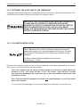
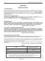
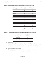
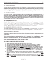
4.3.5 SETTING THE LINE STRAPS
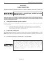
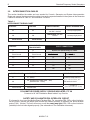
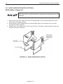
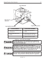
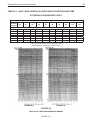
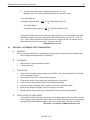
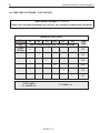
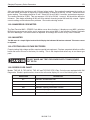
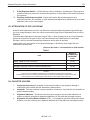
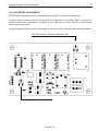
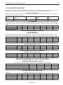
Matching the autotransformer to the incoming line is accomplished with two line straps, one on the Major
KVP Selector Switch and one on the Minor KVP Selector Switch. All nine major voltages, 100 through 260,
from the autotransformer are considered positive numbers. All eight minor voltages, 0 through 18, from
the autotransformer are considered negative numbers. For line matching at installation, measure your line
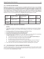
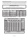
supply voltage. Example: The installation Line Supply voltage is 234. Connect the Major line strap to 240-then
connect the Minor line strap to -5. 240-5 = 235. After line straps have been set, connect a digital voltmeter
between A1 and A2. If line is matched properly, 118-122V should appear between A1 and A2.
See calibration Data Sheet Part 1.
Line Supply
Voltage
Connect Major Line Strap To
Match nearest Line Voltage +
Numbers
Connect Minor Line Strap
To Deduct the Difference
-Numbers
Line/Autotransformer
Match
Measure
Voltage
Between
A1 - A2
Example
234VAC
Connect Major Line Strap to 240
on the Major KVP Switch
Connect Minor Line Strap to
minus (- 5) on the KVP Switch
240-5= 235 VAC
235VAC. The Auto is
matched within 1 volt of
the actual line.
118-122VAC
Your Voltage
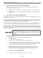
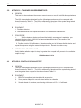
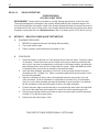
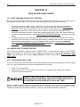
4.3.6 X-RAY CONTROL CHECK OUT PROCEDURE
NOTICE:
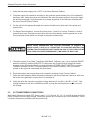
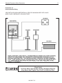
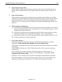
1. Check dials and knobs for looseness and whether they are indicating the correct function. Register
and tighten as needed. Turn Line Power ON, turn Breaker on X-ray Control. Turn Bucky Switch to
OFF.
2. Vary Major and Minor KVP switches and observe the KVP Meter Display .
3. Vary the MA Switch and observe MA and MAS Meter Displays.
4. Vary the Time Select Switch and observe the MAS Displays.
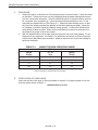
5. DISREGARD KVP METER READOUT AT THIS TIME. Depress rotor button (After 2.2-second delay,
the green ready lamp should light), then depress the exposure push-button.
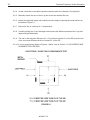
A.
You should hear the back-up contacts close and the console amber exposure lamp light.
C.
An audible signal sounding termination should be observed.
B.
D.
At the end of the exposure, the exposure lamp should extinguish.
If the above conditions are met, the Control is ready for Calibration. Proceed to Section 5.
E. Should an ERROR CODE be displayed, (See ERROR CODE CHART in section 12.6.5).
6. Turn control OFF and connect all test instruments needed for calibrating the X-ray Control.
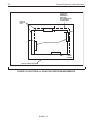
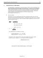
4.3.7 X-RAY BEAM QUALITY AND ALIGNMENT PROCEDURES
X-ray Beam Quality depends on many factors which cannot be explained in such a short space. For this
reason a complete section has been included which explains all facets of testing, adjustments and verification
for X-ray Beam Quality. See Sections 6, 7 and 8.
M-2008-7-13