1
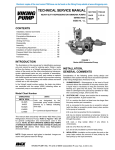
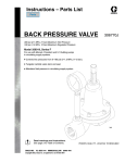
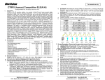
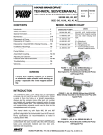
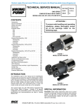
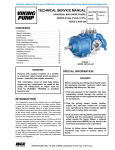
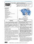
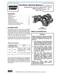
Electronic copies of the most current TSM issue can be found on the Viking Pump website at www.vikingpump.com
TECHNICAL SERVICE MANUAL
HEAVY-DUTY REFRIGERATION AMMONIA PUMPS
SERIES 4925
SIZES HL - LL
SECTION
TSM 420
PAGE
1 OF 18
ISSUE
F
CONTENTS
Installation, General Comments . . . . . . . . . . . . .1
Pump Installation . . . . . . . . . . . . . . . . . . . . .3
Preventative Maintenance . . . . . . . . . . . . . . . .4
Safe Practices . . . . . . . . . . . . . . . . . . . . . . 5
Venting the Pump . . . . . . . . . . . . . . . . . . . . 5
Disassembly . . . . . . . . . . . . . . . . . . . . . . .7
Assembly . . . . . . . . . . . . . . . . . . . . . . . . 10
Thrust Bearing Adjustment . . . . . . . . . . . . . . . 11
Installation of Carbon Graphite Bushings . . . . . . . 12
Pressure Relief Valve Instructions . . . . . . . . . . . 12
Troubleshooting . . . . . . . . . . . . . . . . . . . . 15
Ammonia . . . . . . . . . . . . . . . . . . . . . . . . 16
FIGURE 1
Series 4925 Unmounted Pump
INTRODUCTION
The illustrations in this manual are for identification purposes
only and cannot be used for ordering parts. Obtain a parts
list from the factory or a Viking® representative. Due to the
nature of the pump and the close manufacturing tolerances,
certain replacement parts are only available in assemblies.
Always give complete name of part, part number, and material with the model number and serial number of pump when
ordering repair parts. The pump or pump unit model number
and serial number are on the nameplate.
In the Viking® model number system, the basic size letters
are combined with the series (4925) indicating either an unmounted pump or mounted pump unit.
UNMOUNTED PUMP & UNIT MODEL NUMBERS
UNMOUNTED
UNITS
MECH. SEAL
Units are designated by the
unmounted pump model numbers
followed by a letter(s) indicating
drive style.
HL4925
K4925
KK4925
LQ4925
LL4925
V = V-Belt
R = Viking Speed Reducer
P = Commercial Speed Reducer
This manual deals exclusively with Series 4925 Heavy Duty
Refrigeration Ammonia Pumps. Refer to Figures 1 thru 24
for general configuration and nomenclature used in this
manual. NOTE: DO NOT OPERATE SERIES 4925 PUMPS
AT SPEEDS HIGHER THAN THOSE STATED IN CATALOG
SECTION 420 (Series 4925 Heavy Duty Refrigeration
Ammonia Pumps).
NOTE: Single reservoir sight glass is standard. Images are
shown with optional reservoir fittings.
INSTALLATION,
GENERAL COMMENTS
Consideration of the following points during design and
installation of the system will help ensure successful operation
of the Viking Refrigeration Ammonia Pump.
1. SUBMERGENCE - Submergence is the head of liquid
ammonia above the centerline of the pump suction port.
A liquid head is necessary to keep the ammonia from
flashing as it goes into the pump. The minimum liquid
head or submergence for good pump operation is 4 feet;
this is assuming a large, short suction line.
2. SUCTION LINE - A large, short suction line is necessary
for good operation. A good suction line:
2.1. is a suction line that is at least one size larger than
the pump suction port connection,
2.2. is connected to the pump by an eccentric reducer
(with the offset or eccentric portion down) when suction
to the pump is horizontal,
2.3. is as short as practical for the installation,
2.4. has no strainer (sometimes a temporary strainer is
used during start up to keep weld beads, etc., from going
through the pump),
2.5. uses a long sweep elbow if any elbow is unnecessary,
2.6. has a full flow shut off valve,
2.7. and is fully insulated to prevent heat pickup.
3. INSULATION - Insulation on the suction line and on the
pump helps reduce the amount of heat pickup by the
liquid ammonia.
VIKING PUMP, INC. • A Unit of IDEX Corporation • Cedar Falls, IA 50613 USA
SAFETY INFORMATION AND INSTRUCTIONS
IMPROPER INSTALLATION, OPERATION OR MAINTENANCE OF PUMP MAY CAUSE SERIOUS INJURY
OR DEATH AND/OR RESULT IN DAMAGE TO PUMP AND/OR OTHER EQUIPMENT. VIKING’S WARRANTY
DOES NOT COVER FAILURE DUE TO IMPROPER INSTALLATION, OPERATION OR MAINTENANCE.
THIS INFORMATION MUST BE FULLY READ BEFORE BEGINNING INSTALLATION, OPERATION OR
MAINTENANCE OF PUMP AND MUST BE KEPT WITH PUMP. PUMP MUST BE INSTALLED, OPERATED
AND MAINTAINED ONLY BY SUITABLY TRAINED AND QUALIFIED PERSONS.
THE FOLLOWING SAFETY INSTRUCTIONS MUST BE FOLLOWED AND ADHERED TO AT ALL TIMES.
Symbol
Legend :
!
!
Danger - Failure to follow the indicated
instruction may result in serious injury
or death.
BEFORE opening any liquid chamber (pumping
chamber, reservoir, relief valve adjusting cap fitting,
etc.) be sure that :
● Any pressure in the chamber has been completely
vented through the suction or discharge lines or
other appropriate openings or connections.
● The pump drive system means (motor, turbine,
engine, etc.) has been “locked out” or otherwise
been made non-operational so that it cannot be
started while work is being done on the pump.
WARNING
WARNING
!
WARNING
● You know what material the pump has been
handling, have obtained a material safety data
sheet (MSDS) for the material, and understand
and follow all precautions appropriate for the safe
handling of the material.
!
!
!
!
WARNING
!
WARNING
BEFORE operating the pump, be sure all drive guards
are in place.
DO NOT operate pump if the suction or discharge
piping is not connected.
!
!
DO NOT place fingers into the pumping chamber or
its connection ports or into any part of the drive train
if there is any possibility of the pump shafts being
rotated.
DO NOT exceed the pumps rated pressure, speed, and
temperature, or change the system/duty parameters
from those the pump was originally supplied, without
confirming its suitability for the new service.
!
WARNING
BEFORE operating the pump, be sure that:
● It is clean and free from debris
● All valves in the suction and discharge pipelines
are fully opened.
● All piping connected to the pump is fully supported and correctly aligned with the pump.
● Pump rotation is correct for the desired direction
of flow.
!
WARNING
SECTION TSM 420
ISSUE
F
PAGE 2 OF 18
Warning - In addition to possible serious
injury or death, failure to follow the
indicated instruction may cause damage
to pump and/or other equipment.
INSTALL pressure gauges/sensors next to the
pump suction and discharge connections to monitor
pressures.
USE extreme caution when lifting the pump. Suitable
lifting devices should be used when appropriate. Lifting
eyes installed on the pump must be used only to lift
the pump, not the pump with drive and/or base plate.
If the pump is mounted on a base plate, the base plate
must be used for all lifting purposes. If slings are used
for lifting, they must be safely and securely attached.
For weight of the pump alone (which does not include
the drive and/or base plate) refer to the Viking Pump
product catalog.
DO NOT attempt to dismantle a pressure relief valve
that has not had the spring pressure relieved or is
mounted on a pump that is operating.
AVOID contact with hot areas of the pump and/or
drive. Certain operating conditions, temperature
control devices (jackets, heat-tracing, etc.), improper
installation, improper operation, and improper
maintenance can all cause high temperatures on the
pump and/or drive.
THE PUMP must be provided with pressure protection.
This may be provided through a relief valve mounted
directly on the pump, an in-line pressure relief valve,
a torque limiting device, or a rupture disk. If pump
rotation may be reversed during operation, pressure
protection must be provided on both sides of pump.
Relief valve adjusting screw caps must always point
towards suction side of the pump. If pump rotation is
reversed, position of the relief valve must be changed.
Pressure relief valves cannot be used to control pump
flow or regulate discharge pressure. For additional
information, refer to Viking Pump’s Technical Service
Manual TSM 000 and Engineering Service Bulletin
ESB-31.
THE PUMP must be installed in a matter that allows
safe access for routine maintenance and for inspection
during operation to check for leakage and monitor
pump operation.
4. PUMP SPEED - The slower the operating speed,
the longer the service life. This is particularly true on
refrigeration ammonia pumps where:
4.1.the liquid has virtually no lubrication value or film
strength to prevent surface to surface contact.
4.2.the heat generated by friction can cause the
ammonia to vaporize, which in turn causes cavitation.
ACCUMULATOR
5. TESTING - All Viking Ammonia pumps are tested prior
to shipment, but it is good practice to pressure test the
pump along with the rest of the system before adding
the ammonia. Shipping, storage, and installation all have
strange ways of producing detrimental effects on sound
equipment.
6. SYSTEM CLEANLINESS - Ammonia is a good
detergent, as such it has a tendency to remove all the
dirt, pipe scale, weld beads, and loose or foreign material
in the system. Unfortunately, not all of this material
settles out in traps or can be caught in strainers; and as
a result, a considerable amount goes through the pump.
The abrasive solids going through the pump will cause
excessive wear during the start up of a new system.
Thus the cleaner a new system is before start up, the
less wear and trouble with the pump.
7. STAND BY EQUIPMENT - Stand by equipment is
always good insurance when possible breakdown of
any single piece of equipment could jeopardize the
operation of the entire system. Often on circulating
systems, two pumps are used with operation of the
pumps alternated by day or week. Alternating operation
of the pumps is not always considered the best practice
since both pumps may both wear out at the same time.
If operation of the pumps is not alternated, the stand
by pump should be run for several hours at least once
a month to make sure it is in good operating condition.
Sometimes on large systems three pumps are used;
two running continuously with the third for use as a
standby and for peak loads.
PUMP INSTALLATION
One of the most important considerations on any circulation
Refrigeration Ammonia pump installation is proper design of
the pump inlet line. Refrigeration Ammonia, when stored in
a closed container, will exert a pressure within the container
equal to its saturated vapor pressure. The saturated vapor
pressure of a liquid may be defined as the pressure at
which both liquid and vapor exist in equilibrium in the same
container. The vapor pressure has a different value for each
temperature. The saturated vapor pressure of water at 212ºF
(waters boiling point) is 14.7 PSIA. In other words, when
handling Refrigeration Ammonia, we are handling a liquid,
which is at its boiling point. A slight reduction in the pressure
being exerted on the liquid will cause boiling and thus vapor
formation.
With this information in mind let us examine figure 2, which
illustrates one of the most important considerations when
installing a pump to handle Refrigeration Ammonia.
PUMP
FIGURE 2
As soon as the pump is started and the liquid begins to flow,
the pressure at the pump (P2) will drop by an amount equal
to the pressure loss in the piping between the accumulator
and the pump. When liquid is flowing: P2 = P1 + H - (pressure
loss in the piping).
In order to have an installation in which the pump handles all
liquid and no vapor, the pressure drop in the piping must be
equal to or less than the static head (H) on the pump inlet. If the
piping loss is greater than the static head, the liquid ammonia
will start to boil or vaporize, and the pump will be required to
take in a mixture of liquid and vapor. Since a given weight of
vapor takes up a much greater volume than the same weight
of liquid, handling both liquid and vapor will reduce the liquid
output from the pump. The vapor is compressed back to a
liquid on the discharge side of the pump causing it to be noisy
and to wear rapidly.
Values for pipe friction losses for calculating suction line
pressure drop can be found in refrigeration hand books.
Since Viking pumps are of the positive displacement type,
be sure that there is no obstruction in the discharge line and
that all valves are in operating position before starting the
pump. Factory assembled port orientation will have right
hand port suction and top port discharge unless otherwise
specified. Port location is determined by looking at shaft end
of pump. The pressure relief valve on the pump provides
over pressure protection. Return-to-Tank pressure relief
valves should be mounted on the discharge side of the pump.
Internal type pressure relief valves should be mounted with
the cap pointing towards the suction side of pump. Also see
information under Relief Valve Instructions, page 12. The
Viking pump mounted return-to-tank pressure relief valve
(see Figure 18, page 12 & Figures 19, 20, and 21, page 13)
is fitted with a pressure relief plug to keep a valid off return
line from building up excessive pressures.
The pressure (P1) in the accumulator is equal to the
saturated vapor pressure of the ammonia. When the pump
is not running, the pressure (P2) at the pump inlet is equal to
the tank pressure (P1) plus the static head (H). P2 = P1 + H
SECTION TSM 420
ISSUE
F
PAGE 3 OF 18
DANGER !
Include provision for a pressure relief
device in any part of a pump and piping
system that can be valved off and, thus,
completely isolated. Cold liquid ammonia
when isolated will, as it warms up to
room temperature, expand and exert
tremendous pressures which may rupture
the pump or piping unless relieved.
See Viking Technical Service Manual TSM000 for additional
general installation information.
PREVENTATIVE MAINTENANCE
Series 4925 pumps are designed for long, trouble free life
under a wide variety of application conditions with a minimum
of maintenance. However, the following should be considered:
1. LUBRICATION - 1.1. Periodic external lubrication should
be applied slowly with a hand gun at all lubrication
fittings.
A good quality multi-purpose, polyurea, NLGI #2
grease is satisfactory in the majority of cases, however,
applications involving very low temperatures may
require other types of lubricants. Suggested frequency
of lubrication is once every 500 hours of operation. Refer
to Engineering Service Bulletin ESB-515. Consult the
factory if you have specific lubrication questions.
1.2. Double Mechanical Seal Reservoir: The Series 4925
ammonia pumps are shipped without oil in the reservoir.
Before letting ammonia into a new or rebuilt pump, fill
the reservoir with one pint of light Refrigeration Oil that is
compatible with the Neoprene seal and has a maximum
viscosity of 15,000 SSU at operating temperature.
B. Remove ½ inch NPT oil filler plug in top of reservoir
carefully and allow the small amount of ammonia trapped
in the reservoir to vent.
C. Open oil drain plug and allow old oil to drain.
D. Replace oil drain plug and fill reservoir with light
Refrigeration Oil to within 1½ inch of the top
(approximately 1 pint).
E.
Replace ½ inch NPT oil filler plug in top of reservoir.
F.
Open hand valve.
G. Wait one minute then start the pump and allow it to run
from two to three minutes before the liquid is introduced
into the pump. This will allow the seat to seal itself
properly before the pressure is applied.
NOTE: If your pump has an automatic snap on filler valve
arranged similar to that shown in figure 3, it is not necessary
to stop the pump to add oil to the reservoir. Merely connect
lubrication pump to automatic filler valve. Open manual valve
and fill reservoir with light Refrigeration Oil to approximately
1½ inch from the top. Close manual valve and remove
lubrication pump from filler valve. To change oil: proceed as
indicated in steps A thru G except vent pumping chamber to
atmosphere before changing oil.
2. END CLEARANCE ADJUSTMENT - After long term
operation, it is sometimes possible to improve the
performance of a pump, without major repair, through
adjustment of the end clearance of the pump. Refer to
instruction under Thrust Bearing Adjustment, page
11, for information regarding this procedure.
MANUAL VALVE
FILLER VALVE
Before opening valves and allowing ammonia to fill the
pump be sure the hand valve on the reservoir, shown in
figure 9, is open.
Change the oil in your double seal pump reservoir after
the first 200 hours of operation and then every 1000
hours of operation by the method mentioned below:
A. Stop pump and close hand valve on oil reservoir, see
figure 9.
DANGER !
Be sure ammonia pressure in pump is not
above 5 PSIG when filling reservoir. If pressure
is higher, pumping chamber should be bled
down to reduce pressure to 5 PSIG or below.
(Before bleeding pump, read SAFE PRACTICES
on page 5 and VENTING THE PUMP on pages 5
and 6). Pressure above 5 PSIG in the pump may
cause inner seal seat to be unseated or may
force the faces of the inner seal apart allowing
any dirt accumulated around the inner seat to
be forced between the faces, which may cause
the seal to leak when the pump is started.
SECTION TSM 420
ISSUE
F
PAGE 4 OF 18
FIGURE 3
3. CLEANING THE PUMP - It is good practice to keep the
pump as clean as possible. This will facilitate inspection,
adjustment, and repair work and help prevent overlooking
a dirt covered grease fitting.
4. STORAGE - If pump is to be stored or not used for six
months or more, pump must be drained and a light coat
of light oil must be applied to all internal pump parts.
Lubricate fittings and apply grease to pump shaft
extension. Viking suggests rotating pump shaft by hand
one complete revolution every 30 days to circulate the
oil. Tighten all pump assembly bolts before putting pump
in service after being stored.
MAINTENANCE
IMPORTANT: READ THE FOLLOWING BEFORE
REMOVING A PUMP FROM AN AMMONIA SYSTEM OR
BEFORE STARTING REPAIR WORK ON A PUMP.
Safety Department. The Safety Department of any company
using ammonia should have information about the basic
safety practices and equipment to use when working with
ammonia. The supplier of the ammonia should always have
the same information.
ANSI - American National Standard Institute, Inc.
DANGER !
1430 Broadway
Before opening any Viking pump liquid
chamber (pumping chamber, reservoir, etc.)
Be sure:
New York, New York 10018
1. That any pressure in the chamber has
been completely vented through the
suction or discharge lines or other
appropriate openings or connections.
(See detailed procedure for venting the
pumps, pages 5 and 6).
500 Fifth Avenue
2.
That
the
driving
means
(motor,
turbine,
engine,
etc.)
has
been
“locked out” or otherwise made nonoperational so that it cannot be
inadvertently started while work is being
done on the pump.
111 East Wacker Drive
3. That you know what liquid the pump
has been handling and the precautions
necessary to safely handle the liquid.
Obtain a material safety data sheet (MSDS)
for the liquid to be sure these precautions
are understood.
DO NOT HURRY.
Failure
to
follow
precautionary measures
serious injury or death.
above
listed
may result in
Bulletin ANSI-K61.1
CGA - The Compressed Gas Association, Inc.
New York, New York 10036
Pamphlet G-2 on Anhydrous Ammonia
IIAR - International Institute of Ammonia Refrigeration
1 Illinois Centre
Chicago, Illinois 60601
The above references give specifics on safety practices and
equipment. In addition to those, some general precautions
include:
WORK CAREFULLY.
LOOK AT ANY PRESSURE GAUGES TO DETERMINE
CONDITIONS IN THE SYSTEM.
HAVE PLENTY OF WATER AVAILABLE.
VENTING THE PUMP
1. Stop the pump (some maintenance people close the
inlet shutoff valve before stopping the pump; but, this is
not recommended practice).
AMMONIA (Anhydrous Ammonia, NH3)
2. Close the inlet (suction) side shutoff valve. A in figure 4.
Ammonia is a colorless gas or liquid, has a pungent odor, as
a gas is lighter than air, is easily liquefied by pressure alone,
and is very soluble in water. It boils at -28ºF; vapor pressure
is 16 PSIG at 0ºF, 45 PSIG at 30ºF, 93 PSIG at 60ºF, and 138
PSIG at 80ºF.
3. Close the discharge side shutoff valve. B in figure 4.
DANGER !
Exposure to ammonia causes intense
irritation to the surface tissue of the eyes,
nose, throat, and lungs. Exposure to high
concentrations of ammonia may blind,
burn, strangle, or kill.
ACCUMULATOR
SEE THE “ * ”
ON PAGE 6.
4’
PUMP
SAFE PRACTICES
Basic safety practices and equipment should always be used
when working with ammonia. Only personnel familiar with
ammonia systems should work on these pumps.
A listing of safe practices and equipment are available from
many sources, including those listed below. A copy of such
a listing and safe practices and equipment should be made
available to everyone working where ammonia is used.
FIGURE 4
Schematic of Piping and Valves For a Liquid Ammonia
Recirculating Pump in a Refrigeration System
SECTION TSM 420
ISSUE
F
PAGE 5 OF 18
4. Close all other shut off valves in lines connected to the
pump. Typical shut off valves include valve C in line E*
in figure 4 from the pump mounted return-to-tank type
relief valve to the accumulator or the valve from an in
line mounted safety relief valve to the accumulator or the
valve in a pressurizing line from the high pressure side
of the system to the pump double seal oil reservoir, line
2 in figure 5.
* The segment of line (E in figure 4) between the return
to tank pressure relief valve and the shutoff valve, C,
should include a pressure relief valve vented to a safe
area.
5. Allow ice on pump to melt. This process can be speeded
up by running cold water over the pump.
Start the venting process as soon as convenient after
the ice has been removed from the pump. This will allow
venting the ammonia at the lower pressures of a cold
pump rather than at the high vapor pressures in a room
temperature pump.
For systems with vent (purge or bleed) valves (e.g. D
figure 4) go to step 6; for systems without a vent valve,
go to step 7.
6. A hose should be connected to any vent valve (e.g. D
in figure 4) in the blocked off portion of the system. The
open end of the hose should be placed under water in a
tank containing at least 10 times as much water as there
is ammonia in the blocked off portion of the system or the
end of the hose should be lead to a safe, well ventilated
area. After the hose has been attached and the open
end properly located under water, then open the vent
valve. Check the open end of the hose to make sure
the ammonia is venting. After ammonia has stopped
venting, continue with step 8.
②
⑤
If there is rigid pipe instead of tubing running from the
pump bracket to the double seal oil reservoir, the pipe
union should be loosened carefully until the “psst” is
heard.
If there is no line from the bracket to the reservoir,
carefully loosen the pipe plug (drain), 3 in figure 6
towards the bottom of he bracket. This pipe plug is found
only on the “K”, “KK”, “LQ” and “LL” 4925 pumps. The
small “HL” 4925 does not have one. When working on
an “HL” 4925 that has no line between the bracket and
double seal oil reservoir, carefully loosen the pipe plug,
4 in figure 6, in the suction port of the pump.
8. Carefully loosen any unions or tubing fittings in any other
lines to the pump that have been blocked off by closing
the shutoff valves so that venting from these segments
of the system can be accomplished. Typical of such lines
would be that from the pump mounted return-to-tank
relief valve to the accumulator, E* in figure 4, or a line
from the high pressure side of the system to the double
seal oil reservoir, line 2 in figure 5.
ALWAYS LISTEN FOR THE “PSST” AT ANY POINT
LOOSENED TO PROVIDE VENTING.
9. Carefully loosen the fill plug, 5 in Figure 5, in the top of
the double seal oil reservoir.
10. After the ammonia has stopped venting, turn the pump
shaft, 6 in figure 5, over for at least 10 complete
revolutions. This will make sure that there is no pocket of
accumulated ammonia that has not been exposed to a
venting point.
11. Carefully loosen the plugs, 4 in figure 6 and 7 in figure
5, in the suction and discharge ports of the pump. If
ammonia continues to vent, wait until the venting stops.
When venting from all the loosened connections stops,
then complete the loosening of the fittings and complete
the removal of the plugs.
⑥
⑦
①
FIGURE 5
Viking K4925
Refrigeration Ammonia Pump with Return-To-Tank
Pressure Relief Valve
7.
If there are no vent valves in the blocked off piping, the
Viking Model 4925 ammonia pump should be vented by
carefully loosening the fitting (1 in figure 5) on the lower
end of the tubing that runs from the pump bracket to the
double seal oil reservoir.
THERE SHOULD BE A DISTINCT “PSST” SOUND
WHEN THE AMMONIA VAPOR LIQUID STARTS TO
VENT. LEAVE THE AREA UNTIL THE VENTING IS
COMPLETE.
SECTION TSM 420
ISSUE
F
PAGE 6 OF 18
④
③
FIGURE 6
Viking K4925
Refrigeration Ammonia Pump with Internal
Pressure Relief Valve
12. When all venting has stopped, continue with removing
the pump from the system or disassembly of the pump in
place.
DISASSEMBLY
SEAL CAP
SEAL HOLDER PLATE
DANGER !
SHAFT
Before opening any Viking pump liquid
chamber (pumping chamber, reservoir,
etc.) Be sure:
1. That any pressure in the chamber has
been completely vented through the
suction or discharge lines or other
appropriate openings or connections.
(See detailed procedure for venting
the pumps, pages 5 and 6).
2.That the driving means (motor,
turbine, engine, etc.) has been
“locked out” or made otherwise nonoperational so that it cannot be
inadvertently started while work is
being done on the pump.
3.That you know what liquid the
pump has been handling and the
precautions necessary to safely
handle the liquid. Obtain a material
safety data sheet (MSDS) for the
liquid to be sure these precautions
are understood.
Failure
to
follow
above
listed
precautionary measures may result in
serious injury or death.
NOTE: BE SURE TO READ PAGES 4 THRU 7 PRIOR TO
PUMP DISASSEMBLY.
1. Mark head and casing before disassembly to ensure
proper reassembly. The idler pin, which is offset in pump
head, must be positioned toward and equal distance
between port connections to allow for proper flow of
liquid through pump.
Remove head from pump.
Do not allow idler to fall from idler pin. Tilt top of head back
when removing to prevent this. Avoid damaging head
gasket. If pump is furnished with pressure relief valve,
it need not be removed from head or disassembled at
this point. Refer to Pressure Relief Valve Instructions,
page 12.
2. Remove idler and bushing assembly from the idler pin.
3. Bend up the tang on the lockwasher and use a
spanner wrench to remove the lockwasher and locknut.
NOTE: A piece of brass or wood inserted through the
port opening and between the rotor teeth will keep the
shaft from turning.
LOCKNUT & CAPSCREW
FIGURE 7
4. Loosen the two locknuts and remove the seal holder
plate. For parts identification, see figure 7.
5. Drive the shaft forward approximately ½” and remove
the pair of half round rings (“K” - “LL” size) under the
inner bearing spacer collar or a snap ring (“HL” size) at
the end of the inner bearing spacer collar, see figure 8.
NOTE: The snap ring (“HL” size) or half round rings (“K”
- “LL” size) must be removed before the rotor and shaft
can be removed from the pump. These rings will not
pass through the mechanical seal and bracket bushing.
6. Carefully remove the rotor and shaft. As the shaft is
being removed decreasing shaft diameters tend to allow
the shaft to drop onto the bracket bushing. To avoid
damaging the bracket bushing, support the rotor and do
not allow either end of the shaft to tilt downward.
NOTE: Considerable force may be required to remove
the rotor and shaft from the pump. Be careful as not to
damage seal parts as the rotor and shaft is removed.
Some of the seal parts may fall off when the rotor and
shaft are removed . Place them to the side to be put with
other mechanical seal parts when they are removed.
7. Loosen the four setscrews over the outer and inner end
caps. Remove both end caps, ball bearing, and bearing
spacer collars. See figure 8.
GREASE FITTING LOCATION
SETSCREWS
NYLON INSERT
OUTER END CAP
INNER
END CAP
LOCKWASHER
LOCKNUT
HALF ROUND
RINGS
SHAFT
INNER SPACER
COLLAR
INNER LIP SEAL
OUTER SPACER
COLLAR
OUTER
LIP SEAL
BALL
BEARING
FIGURE 8
NOTE: The inner end cap can be removed through the
side opening in the bracket.
For Viking old series 924 Heavy Duty Refrigeration
Ammonia Pumps go to page 14 for bearing housing
disassembly instructions.
SECTION TSM 420
ISSUE
F
PAGE 7 OF 18
8. The seal seats and rotary members of the seal may be
removed from the side opening of the bracket; see step
11 for removal of the double mechanical seal.
NOTE: Pay particular attention to the location,
arrangement and construction of the seal parts as it will
help considerably when the pump is reassembled.
9. Clean all parts thoroughly and examine for wear or
damage. Check lip seals, ball bearing, bushings, and
mechanical seal and replace as necessary. Check all
other parts for nicks, burrs, excessive wear, and replace
if necessary.
12. Remove the seal cap if it was not removed in step 6. A
light tap may be necessary to loosen it.
NOTE: Be sure that the shaft is free from burrs and
foreign particles that might damage the bracket bushing.
Scratches on the shaft in the seal area will provide
leakage paths under the mechanical seal.
10. Check casing for wear or damage while mounted to the
bracket.
DOUBLE MECHANICAL SEAL
See figure 11. The mechanical seal consists of five basic
parts. They are: inner and outer seal seats with O-ring
gaskets; inner and outer rotary members; and spring.
When pump is running, the seal cap and inner and outer
seal seats with O-ring gaskets remain stationary in the
bracket seal housing bore; the inner and outer rotary
members turn with the shaft.
13. The O-ring gaskets of the seal seats may have become
slightly sealed against the side of the housing and
require extra effort. If this happens, apply light oil in the
seal housing bore in front of the seats so they will slide
freely.
14. After removing the outer seal seat, the outer rotary
member, the spring, and the inner rotary member can be
removed.
15. Remove the inner seal seat and gasket by bending the
ends of two lengths of wire and then by inserting the bent
end in the slots in the bushing and pulling the seal seat
through the housing from the shaft end. If removal is
difficult, an arbor press may be used to push the bracket
bushing, seal seat, and gasket out of the bore from the
rotor end. Another coating of light oil may be helpful to
ease the seal seat out of the housing.
Another way of removing the inner seal seat is to drive
it out while inserting a screwdriver through the bracket
bushing from the casing end so it hits the seal seat at the
notches in the bracket bushing. Be careful and do not
damage the bracket bushing when removing the inner
seal seat in this manner.
11. The pump has now been disabled to the point where the
double mechanical seal may be removed from the seal
housing bore of the bracket.
HAND VALVE
OIL FILLER PLUG
SIGHT
GLASS
THRUST
BEARING
LOCK
WASHER
ADJUSTING
SCREW CAP
OIL RESERVOIR
ADJUSTING
SCREW
CASING
OUTER
END
CAP INNER
END
CAP
LOCKNUT
O-RING
IDLER PIN
POPPET
LOCKNUT
SHAFT
END CAP
SETSCREWS
RETURN-TO-TANK
RELIEF VALVE
IDLER BUSHING
DOUBLE
MECHANICAL
SEAL
VALVE COVER PLATE
OIL
DRAIN
PLUGS
ROTOR
BRACKET
BRACKET BUSHING
FIGURE 9
SECTION TSM 420
ISSUE
F
PAGE 8 OF 18
IDLER
HEAD
FIGURE 10
Exploded View Series 4925
ITEM
NAME OF PART
ITEM
NAME OF PART
ITEM
NAME OF PART
1
Locknut
15
Double Mechanical Seal
29
Rotor & Shaft
2
Lockwasher
16
Reservoir Tubing
30
Idler & Bushing
3
End Cap (Outer)
17
Tube Fittings (2 Req’d)
31
Idler Bushing
4
Lip Seal, Bearing Housing (2 Req’d)
18
Hand Valve
32
O-Ring Gasket, Head
5
Bearing Spacer Collar (Outer)
19
Nipple
33
Idler Pin, Lube
6
Ball Bearing
20
Pipe Plug
34
Check Valve (2 Req’d)
7
Bearing Spacer Collar (Inner)
21
Reservoir with Sight Glass & Plug
35
Head Idler Pin
8
Ring, Half Round (2 Req’d)
22
Nipple
36
Capscrew for Head (6 Req’d)
9
End Cap (Inner)
23
Bracket and Bushing
37
Pipe Plug
10
Seal Holder Plate
24
Bracket Bushing
38
O-Ring Valve Gasket (2 Req’d)
11
Seal Cap
25
Capscrew for Bracket (8 Req’d)
39
Capscrew for Valve & Cover Plate (8 Req’d)
12
Nut for Seal Holder Plate (2 Req’d)
26
Pipe Plug (4 Req’d)
40
Return-To-Tank Relief Valve & Cover Plate
13
Capscrew for Seal Holder Plate (2 Req’d)
27
O-Ring Gasket Bracket
41
Cover Plate, Relief Valve
14
Grease Fitting
28
Casing
SEAL HOUSING BORE
INNER ROTARY MEMBER
SEAL SEAT PIN
SPRING
OUTER ROTARY MEMBER
OUTER SEAL SEAT & GASKET
SEAL SEAT PIN
SEAL CAP
ROTOR & SHAFT
BRACKET BUSHING
INNER SEAL SEAT & GASKET
FIGURE 11
SECTION TSM 420
ISSUE
F
PAGE 9 OF 18
ASSEMBLY
1. Installing a new seal: The seal is simple to install and
good performance will result if care is taken in installation,
see figure 11, page 9 for parts identification.
4. Clean and coat the pump shaft with light Refrigeration
Oil. Check to be sure no scratches have been cut into the
shaft in the seal area.
SPRING
Seals made by different manufacturers are used in these
pumps and are used interchangeably though they may
look different and have a different spring.
MECHANICAL SEAL
(OUTER ROTARY MEMBER)
After all parts have been examined and cleaned or
replaced as necessary, the first step in reassembling the
pump is installation of the inner seal seat.
Good performance will result if care is taken during
installation.
NOTE: Never touch mechanical seal faces with anything
except clean hands, cardboard, or clean cloth. Minute
particles can scratch the seal faces and cause leakage.
COAT WITH LIGHT OIL
BEFORE ASSEMBLY
TAPERED SLEEVE
COAT WITH LIGHT OIL BEFORE ASSEMBLY
FIGURE 14
5. After replacing the casing on the bracket, place the rotor
and shaft into the casing.
NOTE: If the casing is removed from the bracket, be
sure the bracket O-ring is in place before placing casing
on bracket.
6.
SEAL HOUSING BORE
INNER SEAL SEAT
AND GASKET
FIGURE 12
2. Clean the bracket seal housing bore, making sure it is
free of dirt and grit.
3. Coat the outside of the inner seal seat and O-ring gasket
and also the inside diameter of the seal housing bore with
light Refrigeration Oil (not grease), see figure 12. Press
the inner seal seat with O-ring gasket into place in the
seal housing bore with your fingers or by putting a piece
of cardboard over the face of the seal seat and pressing
with a block of wood or squared off piece of pipe. Remove
the cardboard. Figure 13 shows how the inner seal seat
pin fits into either of the slots in the end of the bracket
bushing. Be sure the pin engages one of these slots in
the bushing when you have finished pushing the seal seat
into the seal housing bore. Check by looking through the
bracket bushing from the casing end.
Place the O-ring or head gasket on the head.
7. Coat idler pin with light Refrigeration Oil and place idler and
bushing on idler pin in head. If replacing carbon graphite
bushing, refer to Installation of Carbon Graphite
Bushings, page 12. Install head and idler assembly
onto the pump. Make sure the idler pin, which is offset in
the pump head, is positioned toward and equal distance
between port connections to allow for proper flow of liquid
through the pump. Tighten the head capscrews evenly.
8. Place the tapered installation sleeve (furnished with
replacement seals K-LL size) on the shaft as shown in
figure 14.
9. Clean and oil the I.D. of the inner rotary member, place
on shaft and slide over the tapered installation sleeve
into position against the inner seal seat. Push against
the rubber tail section of the bellows with a sleeve or
smooth piece of pipe having an inside diameter no more
than ¹⁄₃₂ inch larger than the shaft diameter and a wall
thickness of at least ¹⁄₈ inch. Be sure to install correct
end against seal seat, see figure 11, page 9. Be sure
carbon face does not fall out of the rotary member.
10. Slide the spring along the shaft and make sure it seats
properly over the inner rotary member. It may be helpful
to stand pump on end to facilitate centering the spring.
11. Coat the outer seal seat and O-ring gasket with light
Refrigeration Oil. Spread a thin film of grease on the seal
cap. Place the outer seal seat in position on the seal cap.
Make sure the pin in the seal seat engages the hole in
the seal cap. The film of grease will hold these two parts
together; set them aside temporarily.
12. Coat the inside diameter of the outer rotary member with
light Refrigeration Oil. Place it on the shaft and slide over
the tapered installation sleeve until it engages the spring.
Be sure to install the correct end towards the spring, see
figure 11, page 9.
FIGURE 13
SECTION TSM 420
ISSUE
F
PAGE 10 OF 18
13.Quickly install the outer seal seat and cap prepared
in step 11 over the shaft and press down against the
outer rotary member until the seal cap hits the end of the
bracket. This compresses the spring and positions the
outer rotary member. Do not release the seal cap.
14. Still holding the seal cap against the end of the bracket,
place half-moon shaped seal holder plate in position and
tighten the two locknuts uniformly. This holds the seal
cap in position and ensures proper positioning of seal.
NOTE: Do not permit either the inner or outer rotary
member to remain on the shaft in any position other than
their final position for more than 30 seconds since the
rubber bellows of the rotary members have a tendency
to stick to the shaft. If the bellows are not in correct
position, the rotary member will be improperly seated.
15. Remove tapered sleeve.
16. Place the inner bearing spacer collar on the shaft as far
as it will go.
NOTE: First replace the snap ring (“HL” size) or half
round rings (“K” - “LL” size), see figure 15.
GREASE FITTING LOCATION
SETSCREWS
NYLON INSERT
OUTER END CAP
INNER
END CAP
LOCKWASHER
LOCKNUT
HALF ROUND
RINGS
OUTER SPACER
COLLAR
OUTER
LIP SEAL
BALL
BEARING
Remove length of hardwood or brass from port opening.
21. Adjust the pump end clearance as indicated in THRUST
BEARING ADJUSTMENT, below.
22. Insert the pipe plug (drain) into the bracket. Close the
hand valve and fill the reservoir to within 1½ inches of
the top with light Refrigeration Oil. It is recommended
that the oil be drained and the reservoir be refilled after
the first 200 hours of operation and then after every 1000
hours.
NOTE: Re-open the hand valve before the pump is
put into operation. The double mechanical seal will not
function properly if it is exposed to ammonia pressure
with this valve closed.
THRUST BEARING ADJUSTMENT
1. Loosen the square head setscrews over the outer and
inner end caps (two for the HL size, four for the K thru LL
size pumps).
2. Turn the inner end cap clockwise (viewed from shaft
end) until it projects slightly from the bracket exposing
approximately three threads.
SHAFT
INNER SPACER
COLLAR
INNER LIP SEAL
Bend one tang of lockwasher into a slot of the locknut.
If tang does not line up with a slot, tighten locknut until
it does. Failure to tighten locknut or engage lockwasher
tang could result in early bearing failure and cause
damage to rest of pump.
FIGURE 15
17. Press the lip seal (lip toward end of shaft) into the inner
end cap, and insert the end cap through the shaft end of
bracket. With two fingers turn it clockwise (looking at end
of shaft) until it engages the threads. The spanner holes
in the inner end cap must be toward the rotor. Turn the
end cap with a spanner wrench until it projects slightly
into the opening on the side of the bracket.
NOTE: The end cap must not be turned so far that the
lip of the seal drops off the end of the spacer collar on
the shaft or the end cap becomes disengaged with the
threads, see figure 15.
18. Pack the ball bearing with multi-purpose, polyurea, NLGI
#2 grease and place on the shaft and push or gently
drive into place in the bracket.
19. Install the lip seal (lip toward end of shaft) and bearing
spacer in the outer end cap and turn the end cap in the
bracket until tight against the bearing, see figure 15.
*For Viking Old Series 924 Heavy-Duty Refrigeration
Pumps see page 14 for bearing housing disassembly,
assembly, and adjusting instructions.
3. Turn the outer end cap clockwise until the rotor is tight
against the head and the rotor shaft cannot be turned.
4. Make a reference mark on the bracket end, opposite a
notch on the outer end cap. Back off the outer end cap
the required number of notches shown in the table, see
figure 16.
5. Tighten the inner end cap with a spanner wrench. Tap the
spanner wrench lightly but DO NOT OVER TIGHTEN,
as it will only damage the threads.
6. Tighten all the square head setscrews that hold the
inner and outer end caps to prevent their turning in the
bracket.
7. The rotor and shaft should turn smoothly for one complete
revolution. If the rotor and shaft doesn’t turn smoothly, go
back and repeat the Thrust Bearing Adjustment steps 1
thru 7.
Turn Outer End Cap C.C.W.
PUMP
SIZE
No. of Notches
or Length on O.D., Inches
HL
3
¹⁄₂ ”
K - LL
5
²¹⁄₃₂ ”
FIGURE 16
20. Put lockwasher and locknut on shaft. Insert length of
hardwood or brass through port opening between rotor
teeth to keep shaft from turning. Tighten locknut to 50-70
ft.- lbs. torque (HL) or 100-130 ft. - lbs. torque (K - LL).
SECTION TSM 420
ISSUE
F
PAGE 11 OF 18
INSTALLATION OF CARBON
GRAPHITE BUSHINGS
When installing carbon graphite bushings, extreme care
must be taken to prevent breaking. Carbon graphite is a
brittle material and easily cracked. If cracked, the bushing will
quickly disintegrate. Using a lubricant and adding a chamfer
on the bushing and the mating part will help in installation.
The additional precautions listed below must be followed for
proper installation.
1. A press must be used for installation.
2. Be certain bushing is started straight.
FIGURE 18
3. Do not stop pressing operation until bushing is in proper
position. Starting and stopping will result in a cracked
bushing.
4. Check bushing for cracks after installation.
PRESSURE RELIEF VALVE
INSTRUCTIONS
VALVE - LIST OF PARTS
1. Valve Cap
7. Valve Spring
2. Adjusting Screw
8. Poppet
3. Lock Nut
9. Pressure Relief Plug
4. Spring Guide
10.
Cap Gasket
5. Bonnet
11. Bonnet Gasket
6. Valve Body
DANGER !
Before opening any Viking pump liquid
chamber (pumping chamber, reservoir,
etc.) Be sure:
1. That any pressure in the chamber has
been completely vented through the
suction or discharge lines or other
appropriate openings or connections.
(See detailed procedure for venting
the pumps, pages 5 and 6).
FIGURE 17
VALVE - LIST OF PARTS
1. Valve Cap
6. Valve Body
2. Adjusting Screw
7. Valve Spring
3. Lock Nut
8. Poppet
4. Spring Guide
9. Pressure Relief Plug
5. Bonnet
10.
Cap Gasket
2.That the driving means (motor,
turbine, engine, etc.) has been
“locked out” or made otherwise nonoperational so that it cannot be
inadvertently started while work is
being done on the pump.
3.That you know what liquid the
pump has been handling and the
precautions necessary to safely
handle the liquid. Obtain a material
safety data sheet (MSDS) for the
liquid to be sure these precautions
are understood.
Failure
to
follow
above
listed
precautionary measures may result in
serious injury or death.
SECTION TSM 420
ISSUE
F
PAGE 12 OF 18
DISASSEMBLY
NOTE: Mark the valve and head, or casing, to be sure they
are reassembled in the same relative position.
1. Remove end cap. Make sure the bonnet is not loosened
as valve cap is removed.
2. Measure and record the length of extension of the
adjusting screw. Refer to “A” on Figure 17 and 18.
3. Loosen the lock nut and back out adjusting screw until
spring pressure is released.
4. Remove the bonnet, spring guide, spring, and poppet
from valve body. Clean and inspect all parts for wear or
damage and replace as necessary.
ASSEMBLY
Reverse the procedure outlined under disassembly. If valve
is removed for repairs, be sure to replace in same position.
OUT RETURN-TO-TANK
VALVE
CASING
BRACKET
OUT
IN
COVER
PLATE
FIGURE 19
CASING
IN
RETURN-TO-TANK
VALVE
IN
DANGER !
Before opening any Viking pump liquid
chamber (pumping chamber, reservoir,
etc.) Be sure:
1. That any pressure in the chamber has
been completely vented through the
suction or discharge lines or other
appropriate openings or connections.
(See detailed procedure for venting
the pumps, pages 5 and 6).
2.That the driving means (motor,
turbine, engine, etc.) has been
“locked out” or made otherwise nonoperational so that it cannot be
inadvertently started while work is
being done on the pump.
3.That you know what liquid the
pump has been handling and the
precautions necessary to safely
handle the liquid. Obtain a material
safety data sheet (MSDS) for the
liquid to be sure these precautions
are understood.
Failure
to
follow
above
listed
precautionary measures may result in
serious injury or death.
OUT
OUT
RETURN-TO-TANK VALVE
VALVE PORT
COVER PLATE
FIGURE 20
Figure 19 shows the standard pump rotation (clockwise).
When viewing the shaft end, the inlet port is on the right and
the outlet on the top.
If the pump rotation is reversed as shown on figure 20 to
give counterclockwise rotation when viewing the shaft end,
the inlet port is on the top and the outlet port on the right.
On “HL” size pumps equipped with Return-To-Tank pressure
valves, (see figure 17) the cap should point towards the
suction side of pump.
On “K” - “LL” size pumps equipped with return-to-tank
pressure relief valves, (see figure 18) the valve must always
be mounted on the valve port nearest the pump discharge
port, see figure 21. Valve port nearest the pump inlet port
must be covered with the valve cover plate.
PRESSURE ADJUSTMENT
If the pressure setting of the valve is to be changed from that
which the factory has set, the following instructions should be
carefully followed:
IN
RETURN LINE
TO TANK
CONNECTS
HERE
VALVE PORT
COVER PLATE
FIGURE 21
1. Carefully remove valve cap which covers the adjusting
screw. Make sure the bonnet is not loosened as valve
cap is removed.
2. Loosen the locknut, which locks the adjusting screw
so pressure setting will not change during operation of
pump.
3. Install a pressure gauge in discharge line for actual
adjusting operation.
4. Turn adjusting screw in to increase pressure and out to
decrease pressure.
5. With discharge line closed at point beyond pressure
gauge, gauge will show maximum pressure valve will
allow while pump is in operation.
SECTION TSM 420
ISSUE
F
PAGE 13 OF 18
The Viking Over-Pressure Relief Valve is strictly an overpressure relief valve; it is not a pressure regulating valve.
BALL BEARING
BEARING HOUSING
SPACER
COLLAR
SETSCREW
(INNER)
SPACER
COLLAR
(OUTER)
When ordering parts for relief valve, always be sure to give
Model and Serial Number of the pump as it appears on the
nameplate (secured to the pump) and the name of the part
wanted. When ordering springs, be sure to give the pressure
setting desired.
SHAFT
VIKING OLD SERIES 924 HEAVY-DUTY
REFRIGERATION AMMONIA PUMPS
THRUST BEARING DISASSEMBLY,
ASSEMBLY, & ADJUSTMENT
LIP SEALS
END CAP
SNAP RING OR
KEEPER RING
DISASSEMBLY
1. Loosen radial set screws in the outer ring of the bearing
housing, and remove the bearing housing end cap, lip
seal, and bearing spacer collar. Use a spanner wrench
to remove the end cap.
2. Remove the double row ball bearing. The bearing should
be washed thoroughly and examined. If there is any
evidence of wear or damage, a new bearing should be
used.
3. Examine the lip seal in the bearing housing and end
cap. These lip seals are important to the assembly and
should be replaced if not in first class condition. They are
a grease seal for the ball bearing and also act as a shield
to keep dirt and other abrasive particles from entering
the bearing. When installing new lip seals, be sure they
are assembled with the lips facing toward the shaft end.
See figure 22.
FIGURE 22
THRUST BEARING ADJUSTMENT
1. Loosen two axial set screws in the outer face of the
bearing housing and turn the thrust bearing assembly
clockwise until it can no longer be turned by hand. Back
off counterclockwise until the rotor and shaft can be
turned by hand with a slight noticeable drag.
2. For standard end clearance, back off the thrust bearing
assembly the required number of notches or an
equivalent length measured on the outside of the bearing
housing. See the following table.
Return to page 8, step 8, for further disassembly.
ASSEMBLY
1. Place the inner bearing spacer collar on the shaft as far
as it will go.
Turn Outer End Cap C.C.W.
PUMP
SIZE
No. of Notches*
or Length on O.D., Inches
HL
2
¹⁄₂”
K - LL
4
1”
NOTE: First replace the snap ring or keeper rings if
furnished in your pump. See figure 22.
3. Tighten the two axial set screws in the outboard face of
the bearing housing with equal force against the bracket.
Your pump is now set with standard end clearance and
locked.
2. Install the bearing housing with inner lip seal into the
bracket.
NOTE: Be sure the shaft can rotate freely. If not, back off
additional notches and check again.
NOTE: If bearing housing has not been disassembled
or has been pre-assembled skip items 3 and 4.
4. Each additional notch (or each ¼” on the outside
diameter of the bearing housing) is equivalent to an extra
end clearance of .002” on HL size pumps; and .0015” on
K, KK, LQ and LL size pumps.
3. Pack the ball bearing with grease, place on the shaft and
push or gently drive into place in the housing.
4. Turn the bearing housing end cap (with lip seal and
bearing collar inside) into the bearing housing until it is
tight against the bearing. Lock in place by tightening the
radial set screws in the outside diameter of the bearing
housing.
5. Turn the bearing housing assembly clockwise until pump
shaft can no longer be turned by hand. The rotor is now
forced against the head.
6. Install the lockwasher and locknut on the shaft, tighten
lock nut and bend down tang of the lockwasher into slot
of locknut.
NOTE: A piece of brass or wood inserted through the
port opening between the rotor teeth will keep the shaft
from turning.
SECTION TSM 420
ISSUE
F
PAGE 14 OF 18
5. Insert the pipe plug (drain) into the bracket. Close the
hand valve and fill oil reservoir within 1½” of the top with
light Refrigeration Oil. It is recommended that the oil be
drained and the reservoir be refilled after the first 100
hours of operation and then after every 1000 hours.
NOTE: Re-open the hand valve before the pump is
put into operation. The double mechanical seal will not
function properly if it is exposed to ammonia pressure
with the valve closed.
6. Return to Installation of Carbon Graphite Bushings,
page 12, and continue on.
TROUBLESHOOTING
A Viking pump that is properly installed and maintained will
give long satisfactory performance.
If trouble does develop, one of the first steps toward finding
the difficulty is to install a vacuum gauge in the suction line
and a pressure gauge in the discharge line. Readings on
these gauges often give a clue on where to start looking for
trouble.
D. Relief valve bypassing - remove obstruction or
open valve. Weld bead or other foreign material
under poppet - disassemble valve and remove
foreign material. Valve setting too low for differential
pressure required - increase setting or get heavier
spring.
E. Pump rotating wrong way - change direction of
motor rotation or change piping.
F. No liquid in accumulator - check controls.
G. Drive equipment broken - repair or replace.
DANGER !
Before opening any Viking pump liquid
chamber (pumping chamber, reservoir,
etc.) Be sure:
1. That any pressure in the chamber has
been completely vented through the
suction or discharge lines or other
appropriate openings or connections.
(See detailed procedure for venting
the pumps, pages 5 and 6).
2.That the driving means (motor,
turbine, engine, etc.) has been
“locked out” or made otherwise nonoperational so that it cannot be
inadvertently started while work is
being done on the pump.
3.That you know what liquid the
pump has been handling and the
precautions necessary to safely
handle the liquid. Obtain a material
safety data sheet (MSDS) for the
liquid to be sure these precautions
are understood.
Failure
to
follow
above
listed
precautionary measures may result in
serious injury or death.
1. PUMP WILL NOT START TO ROTATE.
A. Motor not hooked up or hooked up correctly - check
wiring.
B. Something has gotten into pump and has jammed
rotating parts - remove head and take out
obstruction.
C. End clearance has been set too close - adjust end
clearance.
D. Drive equipment jammed - remove obstruction.
2. PUMP FAILS TO PUMP.
A. Suction line valve not open - open valve.
B. Suction strainer is plugged - clean strainer.
C. Pump vapor bound - vent discharge lines.
3. PUMP IS NOISY.
A. Cavitation (liquid vaporizing on suction side of
pump) - increase head of liquid on pump; reduce
line loss in suction piping; insulate suction line;
reduce pump speed.
B. Pump is starved due to no liquid in the accumulator
- adjust floats or time cycle.
C. Relief valve chattering - increase pressure setting
of relief valve.
D. Binding - check alignment of unit; check for pipe
strain.
E. Drive equipment worn or damaged
replace.
- repair or
4. LOW CAPACITY
A. Motor running at wrong speed - check wiring.
B. Speed too slow - change drive or get motor with
faster rated speed.
C. Too much end clearance - adjust end clearance.
D. Internal wear - replace worn parts.
E. Pump too small - use a larger pump or two small
ones.
F. Suction line too small - reduce length or increase
size.
G. Relief valve opening - increase pressure setting.
H. Bypass line valve open - adjust valve.
5. RAPID WEAR.
A. Dirt in the system - install suction line strainer
temporarily until system is clean.
B. Cavitation (liquid vaporizing on suction side of
pump) - increase head of liquid on pump; reduce
line loss in suction piping; insulate suction line;
reduce pump speed.
C. Pump misaligned or distorted - check alignment of
unit; check for pipe strain.
D. Running too fast - change drive or use larger pump
that could run slower.
E. Pump runs dry part of time - check level controls to
be sure there is always liquid in the pump.
6. RELIEF VALVE DOES NOT FUNCTION
A. Installed incorrectly - return-to-tank type relief valve
should be mounted on the head opening toward the
discharge side of pump. Internal type relief valve
should be mounted so the cap points toward suction
port of pump.
SECTION TSM 420
ISSUE
F
PAGE 15 OF 18
B. Setting too high - reduce setting or get lighter spring.
C. Valve poppet binding - remove poppet, check for
burrs or foreign material.
D. Shut-off valve in relief valve return line closed - open
valve (would apply only to pumps with return-to-tank
type relief valves).
7. MECHANICAL SEAL LEAK.
A. Normal wear - replace seal.
B. Improper installation - review installation procedure
outlined on pages 10 and 11.
C. Abrasive material in liquid - if abrasive material on
ammonia side, use traps or strainer to clean system;
if on oil side, change oil more frequently and use
clean oil.
D. Pump operating at very low temperature causing oil
to become heavy - use lighter oil or use immersion
heater to heat oil.
AMMONIA
Ammonia (Anhydrous Ammonia, NH3)
Ammonia is a colorless gas or liquid, has a pungent odor, as
a gas is lighter than air, is easily liquefied by pressure alone,
and is very soluble in water or alcohol.
Ammonia is one of the best known and widely used
refrigerants in use today in ice plants, food lockers, cold
storage warehouses, and other industrial cooling processes.
Ammonia has a higher refrigeration effect, per unit of liquid
volume, than any other type of commonly used refrigerant;
other advantages are low initial cost and low pipe friction
losses.
PHYSICAL PROPERTIES
Boiling point (atmospheric pressure)
Freezing point (atmospheric pressure)
Viscosity at -28°F.
Specific Gravity at -28°F.
Liquid Density at -28°F.
Liquid Density at -28°F.
* Latent heat of vaporization at -28°F.
-28°F.
-107.9°F.
0.27 centipose
0.68
42.6 lbs./ft3
5.7 lbs./gal.
589 BTU/lb.
TABLE 1
* (Number of Btu’s to change one pound liquid ammonia
from liquid to gas)
Ammonia, like LP-Gas and other vapor high pressure liquids,
has to be kept in a closed container to keep it from boiling
away. For a given temperature, the pressure built up within
the container is equal to the vapor pressure or saturation
pressure. Conversely for any given pressure, there is a
temperature at which the liquid and vapor are in equilibrium
(saturation temperature); see table 2. If the pressure in the
container is held constant and the vapor is withdrawn, the
ammonia will vaporize (boil). As it boils, it picks up heat
from the area around the container since over 500 Btu’s are
necessary to change one pound of ammonia from liquid to
vapor. If the pressure over the ammonia is reduced, the boiling
temperature will be reduced and the boiling temperature will
be lowered.
SECTION TSM 420
ISSUE
F
PAGE 16 OF 18
Thus the temperature around the container can be controlled
by the pressure maintained in the container. Table 2 shows
the ammonia vapor pressure for various temperatures.
* The same phenomena takes place to lower the boiling point
of water when the pressure is lowered. This explains the low
boiling point of water on a mountain top.
The saturation properties of ammonia make it desirable for
use as a refrigerant. The temperatures necessary for freezing
and keeping food products can be quite easily achieved
with pressures or vacuums readily developed by available
equipment.
SATURATED VAPOR PRESSURE
Temp.
°F.
-100
180
-60
-50
-40
-30
-28
-20
-10
0
10
20
30
40
50
60
80
100
“Hg.
Vacuum
27.4
24.3
18.6
14.3
8.7
1.6
0
PSI
Gage
0
3.6
9.0
15.7
23.8
33.5
45.0
58.6
74.5
92.9
138
197
PSI
Absolute
1.24
2.74
5.55
7.67
10.4
13.9
14.7
18.3
23.7
30.4
38.5
48.2
59.7
73.3
89.2
108
153
212
AMMONIA VAPOR PRESSURE
TABLE 2
Grades of Ammonia Available - commercial grade 99.5%,
refrigeration grade 99.95%.
Explosive Limit in Air, by Volume - 15 to 28%.
Corrosion - Ammonia will not attack iron or steel even in the
presence of moisture; it will attack copper, brass, bronze, and
zinc in the presence of moisture.
Toxicity - Concentrations of ammonia in air as low as 53
parts per million can be detected by the sharp penetrating
odor.
Exposure to ammonia causes intense irritation to the surface
tissues of the eyes, nose, throat, and lungs. Exposure to high
concentration of ammonia may blind, burn, strangle, or kill.
The effect of ammonia on the skin is that of a caustic burn,
varying in severity with the concentration of ammonia and
the length of time exposed. Changes in respiratory and heart
action produced are reflex actions resulting from the irritation
of the respiratory tract.
For information on the safe handling of ammonia, see SAFE
PRACTICES, page 5.
Figure 23 is a schematic of a simple Vapor Ammonia
Refrigeration System with the major pieces of equipment
named and numbered. Each piece of equipment is described
briefly and its function in the system discussed in the following
paragraphs. To illustrate temperatures and pressures that
would exist in a actual illustration, there is given with the
discussion of each piece of equipment the actual temperature
and pressure for a system operating with a condenser
temperature of 86°F and an evaporator temperature of 5°F.
1. RECEIVER - A storage tank for ammonia at ambient
temperatures. The receiver “receives” the liquid ammonia
as it comes from the condenser. The pressure in the
receiver will correspond to the vapor pressure of the
ammonia at the temperature of the cooling medium used
in the condenser. In this case with an 86°F condenser
temperature, the ammonia pressure would be 154 PSI
(the saturation pressure corresponding to a temperature
of 86°F).
2. EXPANSION VALVE - A throttling valve that controls
the amount of liquid that flows into the evaporator. It can
be controlled manually or by thermostats located in the
evaporator. The temperature and pressure of the liquid
on the inlet side of the expansion valve is the same as
that in the receiver (86°F and 154 PSIG); the pressure on
the outlet side of the expansion valve is that maintained
in the evaporator by the compressor; (the compressor
would have to pull down and hold the pressure in the
evaporator at 19 PSIG to maintain the evaporator
temperature at 5°F; this is the saturation temperature
corresponding to 19 PSIG).
3. EVAPORATOR - The evaporator is the main purpose for
the existence of the refrigeration system. It is through
the evaporator that heat is picked up by the ammonia.
The temperature in the evaporator area will be “pulled
down” to the saturation temperature of ammonia at the
pressure maintained by the compressor. The ammonia
enters as a liquid at the temperature in the receiver; it
leaves as a vapor (gas) at the saturation temperature.
(For the system being considered, the pressure in the
evaporator would have to be maintained at 19 PSIG.
This is the pressure corresponding to a saturation
temperature of 5°F).
4. COMPRESSOR - The compressor pulls the ammonia
vapors from the evaporator. The pressure or vacuum
pulled in the evaporator by the compressor will
determine the pressure at which the evaporator works.
The compressor compresses the ammonia gas to the
pressure corresponding to the saturation pressure of
the ammonia at the temperature maintained in the
condenser. The compressed ammonia gas as it leaves
the compressor is hot and is in a super heated vapor
state. (The vapor pulled into the compressor is at 5°F, the
vapor as it leaves is at a temperature of approximately
210°F and a pressure of 154 PSIG. The pressure of 154
PSIG is the saturation pressure of the ammonia at the
86°F condenser temperature).
5. CONDENSER - The condenser cages the super heated
ammonia vapors back to liquid ammonia. It does this
by transferring the heat from the ammonia to a cooling
liquid, such as water flowing through the condenser
tubes. The pressure that the compressor must develop
is determined by the saturation pressure of the ammonia
at the temperature maintained in the condenser. (The
temperature maintained in the condenser by the cooling
medium is 86°F; the saturation pressure at the condenser
temperature is 154 PSIG, which is the pressure that must
be maintained in the condenser to change the ammonia
vapor back to liquid). The liquid ammonia coming from
the condenser is stored in the receiver. From here, it is
ready to start the cycle over again.
6. ACCUMULATOR - The accumulator or low pressure
receiver is not one of the essential pieces of equipment
in the simple system, but in practice, it serves a very
important function. For the proper operation of the
compressor, it is important that no liquid ammonia can be
carried over from the evaporator. The accumulator serves
as a trap to keep liquid ammonia from being entered with
the ammonia vapors that are pulled from the evaporator
by the compressor. (The temperature and pressures are
the same as they are in the evaporator). As the liquid is
collected or accumulated in the accumulator, it must be
removed. THE REMOVAL OF THE LIQUID AMMONIA
FROM THE ACCUMULATOR IS WHERE THE VIKING
REFRIGERATION AMMONIA PUMP IS USED.
(210°F, 154 PSIG)
WATER COOLING PIPES
COMPRESSOR (4)
CONDENSER (5)
(86°F, 154 PSIG)
ACCUMULATOR
(6)
EVAPORATOR (3)
(REFRIGERATOR)
(5°F, 19 PSIG)
VIKING REFRIGERATION AMMONIA
PUMPS USED IN THIS PORTION
OF SYSTEM TO WITHDRAW LIQUID
AMMONIA FROM THE ACCUMULATOR
(5°F, 19 PSIG)
SEE FIGURES 2 & 4
RECEIVER (1)
(86°F, 154 PSIG)
EXPANSION
VALVE (2)
FIGURE 23
Schematic of a Simple Vapor-Compression Ammonia Refrigeration System
SECTION TSM 420
ISSUE
F
PAGE 17 OF 18
TECHNICAL SERVICE MANUAL
HEAVY-DUTY REFRIGERATION AMMONIA PUMPS
SERIES 4925
SIZES HL - LL
Figure 24 shows a typical schematic of a Continuously
Recirculating System with vertical accumulator. Space
or other physical requirements may make a horizontal
accumulator more practical. As long as the minimum
submergence requirement of 4’ of liquid is maintained, the
arrangement of the accumulator is of little consequence
to good pump operation. The schematic is intended only
to show in a general way piping and connections directly
related to the pump. No attempt has been made to show all
the necessary controls, valves, regulators, gauges, etc. that
are necessary for successful operation of this portion of an
ammonia refrigeration system.
ACCUMULATOR
LIQUID
AMMONIA MAKE
UP LINE FROM
HIGH PRESSURE
RECEIVER
TO
COMPRESSOR
RETURN LINE
FROM PUMP
MOUNTED
RELIEF VALVE
THROTTLE
VALVE
EVAPORATORS
THROTTLE VALVE
VIKING REFRIGERATION
AMMONIA PUMP
FIGURE 24
Schematic of Liquid Ammonia Recirculating System
SECTION
TSM 420
PAGE
18 OF 18
ISSUE
F
WARRANTY
Viking warrants all products manufactured by it to be
free from defects in workmanship or material for a
period of one (1) year from date of startup, provided
that in no event shall this warranty extend more than
eighteen (18) months from the date of shipment from
Viking. The warranty period for Universal Seal series
pumps ONLY (Universal Seal models listed below) is
three (3) years from date of startup, provided that in
no event shall this warranty extend more than forty-two
(42) months from the date of shipment from Viking.
UNDER NO CIRCUMSTANCES SHALL VIKING BE
LIABLE UNDER THIS WARRANTY OR OTHERWISE
FOR
SPECIAL,
INCIDENTAL,
INDIRECT,
CONSEQUENTIAL OR PUNITIVE DAMAGES OF ANY
KIND, INCLUDING, BUT NOT LIMITED TO, LOST
OR UNREALIZED SALES, REVENUES, PROFITS,
INCOME, COST SAVINGS OR BUSINESS, LOST OR
UNREALIZED CONTRACTS, LOSS OF GOODWILL,
DAMAGE TO REPUTATION, LOSS OF PROPERTY,
LOSS OF INFORMATION OR DATA, LOSS OF
PRODUCTION, DOWNTIME, OR INCREASED
COSTS, IN CONNECTION WITH ANY PRODUCT,
EVEN IF VIKING HAS BEEN ADVISED OR PLACED
ON NOTICE OF THE POSSIBILITY OF SUCH
DAMAGES AND NOTWITHSTANDING THE FAILURE
OF ANY ESSENTIAL PURPOSE OF ANY PRODUCT.
THIS WARRANTY IS AND SHALL BE VIKING’S SOLE
AND EXCLUSIVE WARRANTY AND SHALL BE IN
LIEU OF ALL OTHER WARRANTIES, EXPRESS
OR IMPLIED, INCLUDING, BUT NOT LIMITED
TO, ALL WARRANTIES OF MERCHANTABILITY,
FITNESS FOR A PARTICULAR PURPOSE AND
NON-INFRINGEMENT ALL OF WHICH OTHER
WARRANTIES ARE EXPRESSLY EXCLUDED.
See complete warranty at www.vikingpump.com.
Pumps on this system run continuously as long as there
is a load on the evaporators. The evaporators are flooded
with several times the amount of ammonia needed; this
helps maintain an even temperature in the evaporators. The
pressure or head differential across the pump is generally very
low; the only head the pump must develop is that required to
over come any elevation head and any line losses.
VIKING PUMP, INC. • A Unit of IDEX Corporation • Cedar Falls, IA 50613 USA
© 3/2014 Viking Pump Inc.
All rights reserved