1
E-90-TSS2:Series QV (F-87)
6/26/08
8:34 AM
Page 1
Bulletin E-90-TSS2
Series TSS2 Dual Stage Temperature Switch
Specifications - Installation and Operating Instructions
°C
1-9/64
[28.97]
1-27/64
[36.12]
3
[76.2]
2-7/16
[61.91]
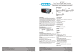
BLUE BUTTONS
WIRING DIAGRAM
The TSS2 is an electronic temperature controller designed for
ON/OFF control or Neutral Area Control. They can be provided
with 1 or 2 probes (both PTC range -58 to 302ºF) according to
parameter P5 and it provides with two output relays plus an alarm
buzzer. The unit controls cooling, heating or both, since its relays
can be setup for direct or reverse operation. The user is able to
program 34 different parameters including set points, hysteresis,
configuration of alarms and probe adjustment using the silicone
front keypad. The unit features error warning and password protection.
Each suffix can take the following values:
MODEL CODE
TSS2 –
OUTPUTS
2 = 2 OUTPUTS
DISPLAY COLOR
0=RED
SUPPLY VOLTAGE
1 = 115 VAC
2 = 230 VAC
3 = 12 VAC/DC
4 = 23 VAC/DC
UNITS
0 = °F
1 = °C
NOTE: Unit must be mounted away from vibration, impacts, water
and corrosive gases.
SPECIFICATIONS
Probe Range: -58 to 302°F (-50 to 150°C).
Input: PTC thermistor (1000Ω @ 25°C).
Outputs: One 16A SPST relay @ 250 VAC, resistive; One 8A
SPST relay @ 250 VAC resistive.
Horsepower Rating (HP): 1/3 HP.
Power Requirements: 12 VAC/DC, 24 VAC/DC, 115 VAC, 230
VAC depending on model.
Accuracy: 1% of full scale.
Display: 3-digit and sign, red LED.
Resolution: 0.1° (<100°); 1° (≥100°).
Memory Backup: Nonvolatile memory.
Ambient Operating Temperature: 32 to 158°F (0 to 70°C).
Storage Temperature: -4 to 176°F (-20 to 80°C).
Dimensions: 3 x 1-27/64 x 2-7/16 in.
Front Panel Rating: IP64.
Weight: 2.3 oz (65 g).
Agency Approvals: CE, UR.
Maintenance, cleaning and repair
After final installation of the unit, no routine maintenance is
required. Clean the surface of the display controller with a soft and
damp cloth. Never use abrasive detergents, petrol, alcohol or solvents. All repairs must be made by authorized personnel.
• Cut hole in panel 71 x 29 mm (2.80 x 1.14 inches).
• Apply silicone (or rubber gasket) around the perimeter of the hole
to prevent leakage.
• Insert unit into hole of panel.
• Slide removable fitting clips onto unit from the back until secure
to panel.
• Wiring diagram is displayed on the top of the unit.
• Note: DO NOT INSTALL PROBE CABLE NEAR POWER
CABLES.
LOVE CONTROLS DIVISION
DWYER INSTRUMENTS INC.
P.O. BOX 338 - MICHIGAN CITY, INDIANA 46361, U.S.A.
Phone: 219/879-8000 www.love-controls.com
Fax: 219/872-9057 e-mail:[email protected]
E-90-TSS2:Series QV (F-87)
6/26/08
8:34 AM
Page 2
page 2
List of parameters
Description
SP1 Set Point 1
SP2 Set Point 2
r0
Dependency SP1-SP2
r1
Differential for SP1
r2
Differential for SP2
r3
Band differential
r4
Lowest value for SP1
r5
Lowest value for SP2
r6
Highest value for SP1
r7
Highest value for SP2
r8
Regulation or operating mode
A0 Alarm differential
A1 Maximum alarm probe 1 (1)
A2 Maximum alarm probe 2 (2)
A3 Minimum alarm probe 1 (1)
A4 Minimum alarm probe 2 (2)
A5 Alarm verification time
A6 Alarm probe 1 selection
A7 Alarm probe 2 selection
c0
Minimum relay stop time
c1
Operation relay 1
c2
Operation relay 2
c3
Default operation relay 1
c4
Default operation relay 2
P0 Temperature scale selection
P1 Calibration of probe 1
P2 Calibration of probe 2
P3 Decimal point
P4 Probe to be displayed
P5 Number of probes
H0 Reprogramming
H1 Keyboard protection
H2 Operation LED OUT1
H3 Operation LED OUT2
H4 Address for serial communication
H5 Access code to parameters
Units
Degrees
Degrees
Range
Degrees
Degrees
Degrees
Degrees
Degrees
Degrees
Degrees
Range
Degrees
Degrees
Degrees
Degrees
Degrees
h-m (*)
Range
Range
Minutes
Range
Range
Range
Range
Range
Degrees
Degrees
Range
Range
Range
Range
Range
Range
Range
Numeric
Numeric
Range
r4 to r6
r5 to r7
ind/dep
0.1 to 20.0
0.1 to 20.0
0.1 to 20.0
-99.9 to r6
-99.9 to r7
r4 to 302
r5 to 302
On1/On2/nEU
0.1 to 20.0
0.1 to 99.9
0.1 to 99.9
0.1 to 99.9
0.1 to 99.9
0.0 to 18.0
AHL/Ano/AH/AL
AHL/Ano/AH/AL
0 to 240
dir/inv
dir/inv
Opn/Clo
Opn/Clo
ºC/ºF
-20.0 to 20.0
-20.0 to 20.0
no/yes
sd1/sd2
1/2
0
no/yes
dir/inv
dir/inv
0 to 999
0 to 999
(*)h-m are data in format XX.Y where XX are hours and Y tens of minutes.
(1)referred to set 1.
(2)referred to set 2.
Parameter descriptions
SP1 = Operation order of relay 1. Specifies the ON/OFF point of
relay 1. Variable between r4 and r6.
SP2 = Operation order of relay 2. Specifies the ON/OFF point of
relay 2. Variable between r5 and r7.
r0 = Dependency between SP1 and SP2. Only for mode ONOFF1
ind = order for relay 2, SP2.
dep = order for relay 2, SP1+SP2.
r1 = Differential or hysteresis for relay 1. Temperature differential between
ON/OFF of relay 1 in ON/OFF control.
r2 = Differential or hysteresis for relay 2. Temperature differential between
ON/OFF of relay 2 in ON/OFF control.
r3 = Band differential. Temperature differential between ON/OFF of relays
1 and 2 in neutral area control. For relay 1 it is added to SP1 and for relay
2 it is subtracted from SP1.
r4 = Lowest value for SP1.
r5 = Lowest value for SP2.
r6 = Highest value for SP1.
r7 = Highest value for SP2.
r8 = Regulation or operating mode. Selection of the operating mode.
A0= Alarm differential. It is the temperature differential between the alarm
On and Off cycle.
A1= Maximum alarm probe1.
A2 = Maximum alarm probe2.
Maximum alarm ON when probe 2 higher than SP2+A2
Maximum alarm OFF when probe 2 lower than SP2+A2-A0.
A3 = Minimum alarm probe1.
Minimum alarm ON when probe 1 lower than SP1-A3
Minimum alarm OFF when probe 1 higher than SP1-A3+A0.
A4 = Minimum alarm probe2.
Minimum alarm ON when probe 2 lower than SP2-A4
Minimum alarm OFF when probe 2 higher than SP2-A4+A0.
A5 = Alarm verification time. Time from the alarm event until it trips.
A6 = Alarm probe 1 selection.
AHL=Maximum and minimum alarm probe 1 enabled.
Ano=No alarms probe 1.
AH=Maximum alarm probe 1 enabled.
AL=Minimum alarm probe 1 enabled.
A7 = Alarm probe 2 selection.
AHL=Maximum and minimum alarm probe 2 enabled.
Ano=No alarms probe 2.
AH=Maximum alarm probe 2 enabled.
AL=Minimum alarm probe 2 enabled.
c0 = Minimum relay stop time. Minimum time from the disconnection
of a relay until it can be switched on again.
c1 = Operation relay 1. Selection between direct or reverse
operation for relay 1.
c2 = Operation relay 2. Selection between direct or reverse
operation for relay 2.
c3 = Default operation relay 1. In case of failure of probe 1:
oPn= relay 1 will remain open.
Clo= relay 1 will remain closed.
c4 = Default operation relay 2. In case of failure of probe 1 (for all
modes excepting ON OFF2) or in case of failure of probe 2 (for
mode ON OFF2):
oPn= relay 2 will remain open.
Clo= relay 2 will remain closed.
P0 = Temperature scale selection.
P1 = Calibration of probe 1. Offset degrees to be added to probe 1.
P2 = Calibration of probe 2. Offset degrees to be added to probe 2.
P3 = Decimal point. If the displayed value of the probes is desired
with decimals or not.
P4 = Probe to be displayed. Probe always on the display. The other
probe can be seen pressing the keys SET+UP.
sd1= probe 1.
sd2= probe 2.
P5 = Number of probes. If P5=1, there is not ON OFF2 mode. If
selected, it will operate as ONOFF1.
H0 = Reprogramming. Parameter to reprogram the thermostat.
H1 = Keyboard protection.
To change the sets, enter into parameter and exit again. The
protection setting is momentarily released. It switches on again
1 minute after the last time a key was pressed.
Yes= Keyboard Protected.
No=Keyboard non protected.
H2 = Operation of LED OUT1.
dir= On when relay 1 is ON.
inv= On when relay 1 is OFF.
H3 = Operation of LED OUT2.
dir= On when relay 2 is ON.
inv= On when relay 2 is OFF.
H4 = Serial communication address. Address for computer
connection.
H5 = Parameter entry code. Factory set as 0.
E-90-TSS2:Series QV (F-87)
6/26/08
8:34 AM
Page 3
Message display
Under normal operation, the temperature of the probe selected by
P4 will be displayed, the following messages may also appear:
•Err Memory reading error.
•ErP Error of the probe not shown on the display.
•AH1 Maximum temperature alarm, probe 1.
•AL1 Minimum temperature alarm, probe 1.
•AH2 Maximum temperature alarm, probe 2.
•AL2 Minimum temperature alarm, probe 2.
•ooo Open probe.
• --- Shorted probe.
Pressing SET with UP it displays the probe not selected by P4.
When the probe not selected by P4 is displayed, it alternates its
value with message Sd1 or Sd2 depending if it is probe 1 or probe 2.
The display blinks when waiting for a value confirmation.
LED indications
Out1: Indicates relay 1 On or Off as per parameter H2. If H2=dir,
with relay 1 On, LED lit, if H2=inv, with relay 1 On, LED off. It blinks
when SP1 is displayed.
Out2: Indicates relay 2 On or Off as per parameter H3. If H3=dir,
with relay 2 On, LED lit, if H3=inv, with relay 2 On, LED off. It blinks
when SP2 is displayed.
Setting SP1 and SP2
• Press and release SET. The current value of order 1 is displayed.
SP1 and led OUT1 blink.
• Press UP or DOWN to increase or decrease the value.
• Press SET to confirm the new value. The actual value of order 2 will
be displayed, SP2 and LED OUT2 blink.
• Press UP or DOWN to increase or decrease the value.
• Press SET to confirm the new value and exit.
Parameter setup
•Press SET for 8 seconds. Value 0 will blink.
•With UP and DOWN input the code (factory set as 0).
•Press SET to confirm the code. If correct, the label of the first
parameter will be displayed.
•With UP or DOWN go to the desired parameter in the parameter
list.
•Press SET to see the value.
•With UP or DOWN change the value to the new value as desired.
•Press SET to confirm and exit again to the parameter list. (Also to
exit to the list without parameter modification.)
•Press SET + DOWN to exit setup or wait for 1 minute.
Resetting the keyboard code
You can setup to 0 the keyboard code switching the unit off and on
while pressing the SET key.
Buzzer disconnection
Pressing SET with DOWN turns off the buzzer alarm. The message
of alarm continue appearing in the display.
Reprogramming factory values (H0)
•Access to parameter H0 as explained in parameter setup.
•Value 0 will be displayed.
•Press SET for 8 seconds. Pro will be displayed if they have been
setup correctly.
•Press SET + DOWN to exit setup or wait for 1 minute.
Description
SP1 Set Point 1
SP2 Set Point 2
r0 Dependency SP1 - SP2
r1 Differential for SP1
r2 Differential for SP2
r3 Band differential 1.0
r4 Lower value for SP1
r5 Lower value for SP2
r6 Higher value for SP1
r7 Higher value for SP2
r8 Regulation or operating mode
A0 Alarm differential
A1 Maximum alarm probe 1
A2 Maximum alarm probe 2
A3 Minimum alarm probe 1
A4 Minimum alarm probe 2
A5 Alarm verification time
A6 Alarm probe 1 selection
A7 Alarm probe 2 selection
c0 Minimum relay stop time
c1 Operation relay 1
c2 Operation relay 2
c3 Default operation relay 1
c4 Default operation relay 2
P0 Temperature scale selection
P1 Calibration of probe 1
P2 Calibration of probe 2
P3 Decimal point
P4 Probe to be displayed
P5 Number of probes
H0 Reprogramming
H1 Keyboard protection
H2 Operation LED OUT1
H3 Operation LED OUT2
H4 Address for serial communication
H5 Access code to parameters
Factory value
10.0
10.0
ind
1.0
1.0
1.0
-99.9
-99.9
99.9
99.9
On1
0.1
99.9
99.9
99.9
99.9
18.0
AHL
AHL
0
dir
dir
Opn
Opn
ºC
0.0
0.0
yes
sd1
2
0
no
dir
dir
0
0
E-90-TSS2:Series QV (F-87)
6/26/08
8:35 AM
Page 4
Operating modes
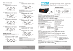
Mode ON OFF1 (On1) with r0=ind.
Relay 1 with c1=dir.
Temperature of probe 1 >= SP1+r1 -->relay 1 ON
Temperature of probe 1 <= SP1 -->relay 1 OFF
Relay 2 with c2=inv.
Temperature of probe 1 <= SP1+SP2-r2 -->relay 2 ON
Temperature of probe 1 >= SP1+SP2 -->relay 2 OFF
Mode ON OFF2 (On2)
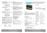
Output 1 works as in independent ON/OFF control (Figure 1 and 2),
but output 2 works as follows:
Relay 2 with c2=dir.
Temperature of probe 2 >= SP2+r2 -->relay 2 ON
Temperature of probe 2 <= SP2 -->relay 2 OFF
Relay 1 with c1=inv.
Temperature of probe 1 <= SP1-r1 -->relay 1 ON
Temperature of probe 1 >= SP1 -->relay 1 OFF
Relay 2 with c2=inv.
Temperature of probe 2 <= SP2-r2 -->relay 2 ON
Temperature of probe 2 >= SP2 -->relay 2 OFF
Relay 2 with c2=dir.
Temperature of probe 1 >= SP2+r2 -->relay 2 ON
Temperature of probe 1 <= SP2 -->relay 2 OFF
Neutral Area Mode (nEU)
Relay 1
Temperature of probe 1 >= SP1+r3 -->relay 2 ON
Temperature of probe 1 <= SP1 -->relay 2 OFF
Relay 2 with c2=inv.
Temperature of probe 1 <= SP2-r2 -->relay 2 ON
Temperature of probe 1 >= SP2 -->relay 2 OFF
Relay 2
Temperature of probe 1 <= SP1-r3 -->relay 2 ON
Temperature of probe 1 >= SP1 -->relay 2 OFF
Mode ON OFF1 (On1) with r0=dep.
Output 1 works as in independent ON/OFF control (Figure 1 and 2),
but output 2 works as follows:
Relay 2 with c2=dir.
Temperature of probe 1 >= SP1+SP2+r2 -->relay 2 ON
Temperature of probe 1 <= SP1+SP2 -->relay 2 OFF
©Copyright 2008 Dwyer Instruments, Inc.
Printed in U.S.A. 6/08
LOVE CONTROLS DIVISION
DWYER INSTRUMENTS INC.
P.O. BOX 338 - MICHIGAN CITY, INDIANA 46361, U.S.A.
Operation in case of error.
If probe 1 fails, the operation is through c3. (See Parameter
description.)
If probe 2 fails, the operation is through c4. (See Parameter
description.)
In case of memory failure, both relays will remain open.
FR# R7-443509-00 Rev.1
Phone: 219/879-8000 www.love-controls.com
Fax: 219/872-9057 e-mail:[email protected]