1
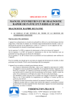
Installation & Service
Manual
NFX, NFSX, NCSX, NFSGX, NCSGX
OPEN WELL FROZEN FOOD & ICE CREAM MERCHANDISERS
Low Temperature Self Serve Display Cases
This manual has been designed to be used in conjunction with the General
(UL/NSF) Installation & Service Manual.
Save the Instructions in Both Manuals for Future Reference!!
This merchandiser conforms to the American National Standard Institute & NSF International Health and Sanitation standard ANSI/NSF 7 - 2003.
PRINTED IN Specifications subject to REPLACES
IN U.S.A.
change without notice. EDITION
1/06
ISSUE
DATE
11/07
Tyler Refrigeration * Niles, Michigan 49120
PART
NO.
9037163
REV.
C
NFX, NFSX, NCSX,
NFSGX, NCSGX
CONTENTS
Page
Specifications
NFX/NFSX/NCSX/NFSGX/NCSGX Specification Sheets . . . . . . . . . 4
Line Sizing Requirements . . . . . . (See General-UL/NSF I&S Manual)
Pre-Installation Responsibilities . . . . . (See General-UL/NSF I&S Manual)
Installation Procedures
Carpentry Procedures . . . . . . . . . . . . . . . . . . . . . . . . . . . . . . . . . . . 7
Case Pull-Up Locations . . . . . . . . . . . . . . . . . . . . . . . . . . . . . . . . . . 7
1” Solid Partition . . . . . . . . . . . . . . . . . . . . . . . . . . . . . . . . . . . . . . . . 7
Plexiglas Partition . . . . . . . . . . . . . . . . . . . . . . . . . . . . . . . . . . . . . . . 7
Trim Installation/Alignment . . . . . . . . . . . . . . . . . . . . . . . . . . . . . . . . . 7
Plumbing Procedures . . . . . . . . (See General-UL/NSF I&S Manual)
Refrigeration Procedures . . . . . . . . . . . . . . . . . . . . . . . . . . . . . . . . 7
Optional Dual Temperature Control . . . . . . . . . . . . . . . . . . . . . . . . . . 7
Electrical Procedures . . . . . . . . . . . . . . . . . . . . . . . . . . . . . . . . . . . . 8
Electrical Considerations . . . . . . . . . . . . . . . . . . . . . . . . . . . . . . . . . . 8
Defrost Information . . . . . . . . . . . . . . . . . . . . . . . . . . . . . . . . . . . . . 8
Defrost Control Chart . . . . . . . . . . . . . . . . . . . . . . . . . . . . . . . . . . . . 8
Installation Procedure Check Lists (See General-UL/NSF I&S Man.)
Wiring Diagrams . . . . . . . . . . . . . . . . . . . . . . . . . . . . . . . . . . . . . . . . . . . . 8
NFX/NFSX/NCSX/NFSGX/NCSGX
Domestic & Export (50 Hz) Case Circuits . . . . . . . . . . . . . . . . . . . . . 9
Dual Temperature Control Circuits . . . . . . . . . . . . . . . . . . . . . . . . 11
Cleaning and Sanitation . . . . . . . . . . . . (See General-UL/NSF I&S Manual)
Component Removal and Installation Instructions for Cleaning 13
Bottom Trays . . . . . . . . . . . . . . . . . . . . . . . . . . . . . . . . . . . . . . . . . . 13
NSF Product Thermometer . . . . . . . . . . . . . . . . . . . . . . . . . . . . . . 13
Discharge Air Honeycomb . . . . . . . . . . . . . . . . . . . . . . . . . . . . . . . 13
Rear Riser Panels . . . . . . . . . . . . . . . . . . . . . . . . . . . . . . . . . . . . . . 13
Front Air Duct Panels . . . . . . . . . . . . . . . . . . . . . . . . . . . . . . . . . . . 13
Rear Riser Canopy Cover . . . . . . . . . . . . . . . . . . . . . . . . . . . . . . . 13
Front Cladding . . . . . . . . . . . . . . . . . . . . . . . . . . . . . . . . . . . . . . . . 13
Page 2
November, 2007
Installation & Service Manual
NFX, NFSX, NCSX,
NFSGX, NCSGX
Page
Service Instructions
Preventive Maintenance . . . . . . (See General-UL/NSF I&S Manual)
Fan Blade and Motor Replacement (See Gen.-UL/NSF I&S Manual)
Color Band and Bumper Replacement (See Gen.-UL/NSF I&S Man.)
NSF Product Thermometer Replacement . . . . . . . . . . . . . . . . . . 14
Defrost Heater Replacement . . . . . . . . . . . . . . . . . . . . . . . . . . . . . .14
Anti-Sweat Replacement . . . . . . . . . . . . . . . . . . . . . . . . . . . . . . . . 15
Front Glass Replacement (NFSGX/NCSGX) . . . . . . . . . . . . . . . . 15
Parts Information
Cladding and Optional Trim Parts List . . . . . . . . . . . . . . . . . . . . . 16
Operational Parts List . . . . . . . . . . . . . . . . . . . . . . . . . . . . . . . . . . 18
TYLER Warranty . . . . . . . . . . . . . . . . . (See General-UL/NSF I&S Manual)
The following Low Temperature Open Well Frozen Food and Ice Cream Merchandiser models
are covered in this manual:
MODEL
DESCRIPTION
NFX/NFSX
8’ & 12’ OPEN WELL FROZEN FOOD MERCHANDISER
NCSX
8’ & 12’ OPEN WELL ICE CREAM MERCHANDISER
NFSGX
8’ & 12’ GLASS FRONT OPEN WELL FROZEN FOOD MERCHANDISER
NCSGX
8’ & 12’ GLASS FRONT OPEN WELL ICE CREAM MERCHANDISER
November, 2007
Page 3
NFX, NFSX, NCSX,
NFSGX, NCSGX
SPECIFICATIONS
NFX/NFSX/NCSX/NFSGX/NCSGX Open Well FF & IC Merchandisers
Page 4
March, 2008
Installation & Service Manual
March, 2008
NFX, NFSX, NCSX,
NFSGX, NCSGX
Page 5
NFX, NFSX, NCSX,
NFSGX, NCSGX
Page 6
March, 2008
Installation & Service Manual
NFX, NFSX, NCSX,
NFSGX, NCSGX
INSTALLATION PROCEDURES
Carpentry Procedures
Case Pull-Up Locations
1. Install partition brackets (1) at case joint
on front, center and/or rear case wall (2)
with screws 3)
2. Slide plexiglas partitions (4) into partition
brackets (1).
Trim Installation/Alignment
The NFX/NFSX/NCSX/NFSGX and NCSGX
models have two pull-ups at each end of the
case. Pull-ups A and B are located as shown
and used for joining all cases.
1” Solid Partition
A 1” insulated partition is required between
adjacent gas defrost cases that are on different
refrigeration systems. 1” partitions are shipped
installed as specified in the case order. Make
sure the partitioned case is being installed in
the proper location in the case line-up. This
assures proper refrigeration to all parts of the
case line-up.
Apply sealant to outside surface of partition
where the two surfaces of the adjoining case
will contact the partition.
See “General-UL/NSF I&S Manual” for
line-up assembly instructions.
After all case pull-ups have been secured, all
interior wall joint seams should be sealed with
duct tape.
Plexiglas Partition
A plexiglas plug partition is required on adjacent electric defrost cases that are on different
refrigeration systems. These partitions can be
installed after the cases have been joined.
January, 2006
See “General-UL/NSF I&S Manual” for
bumper, color band, raceway and kickplate
installation.
Refrigeration Procedures
See “General-UL/NSF I&S Manual” for
general system, control and superheat
information.
Optional Dual Temperature Control
The dual temperature control unit is a factory
installed option. This control allows the user
to easily switch from medium to low temperature operation by flipping a switch. The dual
temperature control consists of an EPR valve
in the suction line coming off the evaporator.
The EPR valve can be bypassed with a solenoid controlled bypass line around it. The
toggle switch opens or closes this solenoid.
When the solenoid is open, the evaporator is
connected directly to the compressor suction
that allows for low temperature operation.
When the solenoid is closed, the evaporator
must operate through the EPR valve which
has been preset to the desired medium
temperature.
EXAMPLE: R-404A system with 12 psig of
suction pressure. With the suction line solenoid open, the coil pressure operates at 12
psig with a temperature of -29°F. When the
Page 7
NFX, NFSX, NCSX,
NFSGX, NCSGX
toggle switch is flipped, the solenoid closes
directing the flow through the EPR valve. If
the EPR valve is set for 48 psig, the evaporator will see a coil temperature of 12°F and will
operate at a discharge air temperature of
about 22°F.
Defrost Information
When gas defrost is used, an additional
check valve is mounted around the EPR valve
to allow reverse flow for the defrosting gas.
A fan delay is also connected with gas defrost
to cycle the fans off, but only during the
medium temperature mode.
NFX/NFS(G)X/NCS(G)X
Defrost
Defrost Defrosts Duration
Per Day
(Min)
Type
Electric/FF 1
60
Elec/IC/MED 1
36
Gas/FF
2-3
20-25
Gas/IC
1
25-30
Gas/MED 2-3
16-20
Electrical Procedures
Electrical Considerations
CAUTION
Make sure all electrical connections are
tight. This prevents burning of electrical
terminals and/or premature component
failure.
NOTE
The raceway houses the electrical wiring
and components for the case. All raceway
covers will be shipped loose.
Defrost Control Chart
Term.
Temp.
50°F
50°F
55°F
55°F
55°F
Most klixons are located on the end of the
evaporator coil. Klixon uses are as follows:
Electric Defrost Termination, Electric Defrost
Failsafe (Opt.), Gas Defrost Fan Delay (Dual
Temp) and Glass Anti-Sweat (Dual Temp).
NOTE
The defrost termination klixon for gas
defrost is located at the bypass check
valve.
CAUTION
Case Fan Circuit
This circuit is to be supplied by an uninterrupted, protected 120V circuit. The case fan
circuit is not cycled, except when equipped
for gas defrost. On gas defrost cases the fan
circuit is controlled by a 50/40 klixon when
used for medium temperatures.
NOTE
With gas defrost, the fans will not start
until the coil temperature reaches 40°F at
the fan delay klixon.
Anti-Sweat Circuit
All cases have at least one anti-sweat heater
in each discharge air grid and return air grid.
Cases with front glass have an additional
anti-sweat heater under the glass retainer.
Anti-sweat heaters are wired directly to the
main power supply so they can operate at
all times.
Page 8
See “General-UL/NSF I&S Manual” for
operational descriptions for each type of
defrost control.
If electronic sensors are used in place of
the klixons, the sensors must be located
in the same location as the klixons for that
defrost type. Any other locations will effect
the refrigeration efficiency of the case.
WIRING DIAGRAMS
ELECTRICIAN NOTE - OVERCURRENT
PROTECTION
120V circuits should be protected by 15 or 20 Amp
devices per the requirements noted on the cabinet
nameplate or the National Electrical Code, Canadian
Electrical Code - Part 1, Section 28. 208V defrost
circuits employ No. 12 AWG field wire leads for field
connections. On remote cases intended for end to
end line-ups, bonding for ground may rely upon the
pull-up bolts.
The following wiring diagrams on pages 9 thru
11 will cover the NFX/NFSX/NCSX/NFSGX/
NCSGX case circuits and dual temp circuits
with electric and hot gas defrost options.
November, 2007
NFX/NFSX/NCSX/NFSGX/NCSGX Domestic & Export (50 Hz) Case Circuits
November, 2007
Page 9
Page 10
November, 2007
Dual Temperature Control Circuits
November, 2007
Page 11
Page 12
November, 2007
Installation & Service Manual
CLEANING AND SANITATION
Component Removal and
Installation Instructions for
Cleaning
Bottom Trays
NFX, NFSX, NCSX,
NFSGX, NCSGX
Rear Duct Panels
1. Remove bottom trays and discharge air
honeycomb, see this page.
2. Remove mounting screws from rear
duct panel.
3. After cleaning, replace in reverse order.
1. Remove product from bottom of case.
2. Grasp and lift out each of the bottom trays
from the case interior and carefully
remove through the door openings
3. After cleaning, replace in reverse order.
NSF Product Thermometer
Remove four screws and product thermometer bracket assembly from right rear location
in the case. After cleaning, replace product
thermometer bracket assembly and secure
with four screws.
Discharge Air Honeycomb
1. Remove screws and bottom retainer strip
from front or rear interior of case.
NOTE
Note position of the honeycomb grid
during removal so it can be reinstalled
the same way.
2. Remove honeycomb grid sections from
the front or rear duct.
CAUTION
Improper installation of the honeycomb
grid section could result in improper air
flow and/or poor refrigeration.
Front Air Duct Panels
1. Remove bottom trays, see this page.
2. Remove screws and front air duct panels
from case.
3. After cleaning, replace in reverse order.
Rear Riser Canopy Cover
(NFSX/NCSX/NFSGX/NCSGX)
1. Remove screws and rear riser joint trim.
2. Remove screws, price tag molding and
rear riser canopy cover from top of case.
3. After cleaning, replace rear riser canopy
cover and remaining components in
reverse order.
Front Cladding
1. Remove front kickplate and raceway
cover.
2. Remove screws from bottom and top of
front cladding and pull cladding down to
remove it from behind the bottom edge
of the bumper retainer.
3. After cleaning, replace front cladding
and remaining front components in
reverse order.
3. After cleaning, replace honeycomb grid
sections as they were removed and
secure with the bottom retainer strip
and screws.
November, 2007
Page 13
NFX, NFSX, NCSX,
NFSGX, NCSGX
SERVICE INSTRUCTIONS
See “General-UL/NSF I&S Manual” for fan
blade and motor replacement, color band
and bumper replacement and raceway
cover removal instructions.
NSF Product Thermometer
Replacement
1. Remove bottom trays from case.
2. Unclip and lift up fan plenum (1).
1. Remove four screws (1) and thermometer
bracket (2) from rear of case.
2. Remove two screws, nuts, washers and
the product thermometer (3) from the
thermometer bracket (2).
3. Install and secure a new product thermometer (3) on the thermometer bracket
(2) with two screws, washers and nuts.
4. Install thermometer bracket (2) on rear of
case with four screws (1).
Defrost Heater Replacement
3. Disconnect defective defrost heater (2)
and remove from mounting clips (3)
and case.
4. Install new defrost heater (4) in reverse
order.
5. Restore electrical power to case.
Anti-Sweat Replacement
WARNING
Shut off or disconnect power supply
to case before changing an anti-sweat.
Electrical power from wire ends could
damage other components and/or cause
personal injury or death.
WARNING
Always shut off electricity to case before
replacing a defrost heater. Automatic
cycling of fans or electrical power to wire
ends could cause personal injury and/or
death.
Page 14
November, 2007
Installation & Service Manual
Discharge Air Grid Anti-Sweat
(NFX Only)
NFX, NFSX, NCSX,
NFSGX, NCSGX
Front Glass Replacement
(NFSGX/NCSGX)
1. Remove screws and rear guard trim (1)
from top of rear case wall (2).
2. Disconnect or cut the defective anti-sweat
wire (3) from the case wires.
3. Remove and replace the aluminum tape
(4) and defective anti-sweat wire (3) from
top of rail and wire trim assembly (5).
4. Reconnect anti-sweat wires to case wires.
Reinstall rear guard trim (1) and secure
with screws.
Canopy Anti-Sweat Locations
(NFSX/NCSX/NFSGX/NCSGX)
Night Cover Shelf
with Light
1. Unplug or disconnect heated glass
panels and glass retainer anti-sweat
wires (1).
2. Remove two screws (2) and glass joint
trim (3) from both joints of the broken
glass (4).
3. Remove screws (5) and glass trim rail (6)
from top of glass (4).
4. Loosen rear retainer (7) and remove
broken glass (4) from glass retainer
assembly (8).
NOTE
Inspect the anti-sweat wire in glass
retainer assembly. If wire is damaged or
broken, replace it before replacing the
front glass.
5. Apply sealant tape to top and bottom
edge of new glass (4).
Night Cover Shelf
without Light
6. Position new glass (4) in glass retainer
assembly (8) and secure by tightening
rear retainer (7).
7. Install glass trim rail (7) with screws (6)
over top edge of new glass (4).
8. Install glass joint trim (3) with two screws
(2) over the joint areas of glass (4).
9. Reconnect heated glass panels and glass
retainer anti-sweat wires (1).
November, 2007
Page 15
NFX, NFSX, NCSX,
NFSGX, NCSGX
PARTS INFORMATION
Cladding and Optional Trim Parts List
Item
1
2
3
4
5
6
7
8
9
10
11
12
13
14
15
16
17
18
19
20
21
22
23
24
25
26
27
28
Description
Screw (NFX)
Lower Rear Riser Joint Trim (NFX)
Top Rear Riser Joint Trim (NFX)
Screw (NFX)
Screw (NFS(G)X/NCS(G)X)
Top Shelf Joint Trim
(NFS(G)X/NCS(G)X)
Lower Top Shelf Joint Trim
without light)(NFS(G)X/NCS(G)X)
Screw (NFS(G)X/NCS(G)X)
Screw (NFS(G)X/NCS(G)X)
Lower Top Shelf Joint Trim
(with light)(NFS(G)X/NCS(G)X)
Screw
Return Air Duct Joint Trim
Hand Rail Backer
Color Band Backer, Ptd.
(NFX/NFSX/NCSX)
Bumper Backer
Horizontal Joint Trim
Cladding Retainer
Screw
Raceway Cover Backer
Raceway
Screw
Kickplate Hanger
Screw
Raceway Cover End Trim
Raceway Cover Retainer
Screw
Metal Kickplate, Ptd.
Kickplate Joint Trim, Ptd.
Screw, BLK.
Shoulder Screw
Kickplate Support Assy.
Raceway Cover
Shoulder Screw
Front Cladding, Ptd.
(NFX/NFSX/NCSX)
Page 16
NFX, NFSX, NCSX, NFSGX and NCSGX
8’
12’
5205439 (4)
5205439 (4)
5182434
5182434
5629361
5629361
5058099 (4)
5058099 (4)
5058099 (4)
5058099 (4)
5629360
5629360
5182435
5205439 (4)
5205439 (2)
5182435
5205439 (4)
5205439 (2)
5128761
5145037 (4)
5203017
9025316
9040223
5128761
5105037 (4)
5203017
9025316
9040223
---- color per order ---5127503
5127503
9300197 (4)
9300197 (4)
5183536 (8)
5183536 (8)
---- color per order ---9300218
9300219
5183536 (18)
5183536 (18)
9300210 (6)
9300210 (8)
5183536 (12)
5183536 (16)
---- color per order ---9023841 (4)
9023841 (6)
5183536 (8)
5183536 (12)
9324399
9324406
9324550
9324550
9324612 (6)
9324612 (6)
9025833 (6)
9025833 (8)
(3)
(4)
---- color per order ---9025833 (18)
9025833 (26)
9025637
9025638
November, 2007
Installation & Service Manual
NFX, NFSX, NCSX,
NFSGX, NCSGX
Item Description
8’
12’
Front Cladding, Ptd, (NFSGX/NCSGX) 9036715
9036716
29 Bumper
---- color per order ---30 Color Band, Ptd. (NFX/NFSX/NCSX)
9023798
9023800
31 Bumper Retainer/Hand Rail
---- color per order ---Bumper Retainer
9025058
9025061
32 Bumper End Trim
---- color per order ---33 Glass Trim (NFSGX/NCSGX)
9031808
9031808
34 Screw
5048626 (2)
5048626 (2)
35 Color Band, Ptd (NFSGX/NCSGX)
9020971
9020972
Color Band Backer (NFSGX/NCSGX)
9025982
9025982
November, 2007
Page 17
NFX, NFSX, NCSX,
NFSGX, NCSGX
Operational Parts List
(Models NFX/NFSX/NCSX/NFSGX/NCSGX)
Case Usage
Electrical Circuit
Domestic
115 Volt 60 Hertz
Export
220 Volt 50 Hertz
Case Size
8’
12’
8’
12’
Fan Motor
5125532
5 Watt
5125532
5 Watt
5126572
5 Watt
5126572
5 Watt
Fan Motor Brackets
5213132
5213132
5213132
5213132
Fan Bracket Plate
9041077
9041077
9041077
9041077
Fan Blades (6” 21° 3B)
5105621
5105621
----
----
----
----
5104294
5104294
9025002
8 Watt
9025002
8 Watt
----
----
Opt. ECM Fan Motor Brackets 5205279
5205279
----
----
Opt. ECM Fan Blades
(6” 25 1/4° 3B)
9025138
9025138
----
----
Anti-Sweat Heater Wire
(Hi-Watt)
5124818
5124819
5081149
5081150
(Lo-Watt)
5124216
5124217
5081147
5081148
(glass retainer)
(NFSGX/NCSGX)
5218331
5218332
5081149
5081150
Electric Def. Heater
5960934
5960935
5088278
5088279
Electric Def. Term. Klixon
5125211
5125211
5125211
5125211
Opt. Gas Def. Fan Delay Klixon 9023503
9023503
9023503
9023503
Opt. Gas Def. Term. Klixon
9023508
9023508
9023508
9023508
T-8 Electronic Ballast
(NFS(G)X/NCS(G)X)
(rear shelf)
5991029
5991030
9028437
9028438
5092414
5092414
5092414
5092414
5967100
5967100
5967100
5967100
(6” 27° 3B)
Opt. ECM Fan Motor
T-8 Lampholder
NSF Product Thermometer
For information on operational parts not listed above contact the TYLER Service Parts
Department.
Page 18
November, 2007