1
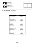
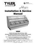
Installation & Service
Manual
L6FA
MULTI-SHELF FROZEN FOOD MERCHANDISER
Low Temperature Self Serve Display Cases
This manual has been designed to be used in conjunction with the General
Installation & Service Manual.
Save the Instructions in Both Manuals for Future Reference!!
This merchandiser conforms to the Commercial Refrigeration Manufacturers Association Health and Sanitation standard CRS-S1-96.
PRINTED IN Specifications subject to REPLACES
IN U.S.A.
change without notice. EDITION
7/99
ISSUE
DATE
1/00
Tyler Refrigeration Corporation * Niles, Michigan 49120
PART
NO.
9027522
REV.
D
Installation & Service Manual
L6FA
CONTENTS
Page
Specifications
L6FA Specification Sheets . . . . . . . . . . . . . . . . . . . . . . . . . . . . . . . 4
Pre-installation Responsibilities . . . . . . . . . . . (See General I&S Manual)
Installation Procedures
Carpentry Procedures . . . . . . . . . . . . . . . . . . . . . . . . . . . . . . . . . 6
Case Pull-Up Locations . . . . . . . . . . . . . . . . . . . . . . . . . . . . . . . . . 6
Electrical Procedures . . . . . . . . . . . . . . . . . . . . . . . . . . . . . . . . . . 6
Plumbing Procedures . . . . . . . . . . . . . . (See General I&S Manual)
Refrigeration Procedures . . . . . . . . . . . (See General I&S Manual)
Defrost Information . . . . . . . . . . . . . . . . . . . . . . . . . . . . . . . . . . . . 7
Defrost Control Chart . . . . . . . . . . . . . . . . . . . . . . . . . . . . . . . . . . . 7
Installation Procedure Check Lists . . . . (See General I&S Manual)
Wiring Diagrams . . . . . . . . . . . . . . . . . . . . . . . . . . . . . . . . . . . . . . . . . . . 7
L6FA Domestic & Export (50Hz) Case Circuits with Electric Defrost 8
L6FA Domestic & Export (50Hz) Case Circuits with Gas Defrost . . 10
Cleaning and Sanitation . . . . . . . . . . . . . . . . . . (See General I&S Manual)
General Information
Night Curtains and Strip Doors . . . . . . . . . . . . . . . . . . . . . . . . . . 12
Case Shelving Information . . . . . . . . . . . . . . . . . . . . . . . . . . . . . . 12
Service Instructions
Preventive Maintenance . . . . . . . . . . . . (See General I&S Manual)
Ballast and Lighting Locations . . . . . . . . . . . . . . . . . . . . . . . . . . 13
Fan Locations . . . . . . . . . . . . . . . . . . . . . . . . . . . . . . . . . . . . . . 13
Checking Air Velocities . . . . . . . . . . . . . . . . . . . . . . . . . . . . . . . 13
Cleaning Honeycomb . . . . . . . . . . . . . . . . . . . . . . . . . . . . . . . . . . 14
Anti-Sweat Heater Replacement . . . . . . . . . . . . . . . . . . . . . . . . 14
Defrost Heater Replacement . . . . . . . . . . . . . . . . . . . . . . . . . . . 15
Ambient Air Filter Replacement . . . . . . . . . . . . . . . . . . . . . . . . . 15
Parts Information
Cladding and Optional Trim Parts List . . . . . . . . . . . . . . . . . . . . 16
Operational Parts List . . . . . . . . . . . . . . . . . . . . . . . . . . . . . . . . . 18
TYLER Warranty . . . . . . . . . . . . . . . . . . . . . . . (See General I&S Manual)
The following Low Temperature, Multi-Shelf Frozen Food Merchandiser models are covered
in this manual:
MODEL
DESCRIPTION
L6FA
6’, 8’ & 12’ MULTI-SHELF FROZEN FOOD MERCHANDISER
July, 1999
Page 3
L6FA
Tyler Refrigeration
SPECIFICATIONS
L6FA Multi-Shelf Frozen Food Merchandiser Specification Sheets
Page 4
January, 2000
Installation & Service Manual
L6FA
L6FA Multi-Shelf Frozen Food Merchandiser
July, 1999
Page 5
L6FA
Tyler Refrigeration
INSTALLATION PROCEDURES
Electrical Procedures
Carpentry Procedures
Electrical Considerations
Case Pull-Up Locations
CAUTION
Make sure all electrical connections at
components and terminal blocks are tight.
This will prevent burning of electrical terminals and/or premature component failure.
NOTE
• Lower raceway cover will be shipped
loose. See the “General I&S Manual”
for raceway cover installation and
removal instructions.
• Since 208V defrost wiring enters the
rear of the case through the outer air
band, the exterior and interior access
holes must be caulked to maintain air
band separation.
Case Fan Circuit
All L6FA models have four pull-ups at each end
of the case. Pull-ups A, B, C and D are located
as shown and should be installed and tightened starting with A and finishing with D.
See “General I&S Manual” for line-up
assembly instructions.
This circuit has three sets of fans (primary,
secondary and ambient) that are supplied by
an uninterrupted, protected 120V circuit. The
case fan circuit is not cycled, except when
equipped for gas defrost. On gas defrost
cases the primary fans are controlled by a
60/30 klixon.
NOTE
With gas defrost, the primary fans will not
restart until the coil temperature reaches
30°F at the fan delay thermostat.
Fluorescent Lamp Circuit
The standard case lighting system is T-8 electronic lamps. The standard lighting is 2-row
of horizontal canopy lights and 1-row of nose
lights.
Page 6
July, 1999
Installation & Service Manual
Defrost Information
See “General I&S Manual” for operational
descriptions for each type of defrost control.
Defrost Control Chart
Defrost
Type
Electric
Gas
Defrost
Defrosts Duration
Per Day
(Min)
2-3
35
3-4
22-25
Term.
Temp.
55°F
60°F*
*Use 70°F with electronic defrost sensor.
The diagram shows the location for each
defrost type that uses a klixon.
NOTE
• The termination thermostat (55/35
Settings) for electric defrost is located in
the right hand end of the upper electrical
raceway.
• The termination thermostat for gas
defrost is located next to the rear coil
bypass check valve.
CAUTION
If electronic sensors are used in place of the
klixons, the sensors must be located in the
same location as the klixons for that defrost
type. Any other locations will effect the
refrigeration efficiency of the case.
L6FA Optional Hot Gas Defrost
Operation Requirements.
When reverse cycle gas defrosting option is
used, it should only be applied to multiple
compressor systems (Parallel racks). A maximum of not more than 25% of the load on a
January, 2000
L6FA
given rack should defrost at one time
because the defrosting cases become a condenser during the defrost period and the
other refrigerated cases must provide enough
heat load to keep a compressor operating.
Do not defrost more than 24 feet of the L6FA
at one time to limit the amount of refrigerant
used in that circuit during the defrost.
Insulated partitions must be used between
cases in the same lineup that have different defrost times.
Defrosts are initiated by a multi-circuit defrost
clock or an electronic defrost controller. At
the beginning of gas defrost the refrigeration
is stopped and the gas is diverted in a
reverse direction through the suction line to
the display case. The refrigeration should be
set to remain off for the complete failsafe time
plus a 5 minute drain off or clear time period.
This type of defrost operation allows the
problem areas in the case to completely clear
without subjecting the refrigerated product to
excessive warm up.
A defrost termination “klixon type” open on
rise thermostat is mounted (on the left hand
side) next to the rear coil check valve that
bypasses defrost refrigerant flow around the
expansion valve. The defrost termination
device along with the mechanical or electronic defrost control should be set up to cycle or
pulse the hot gas valve during the defrost
time period. If you use a mechanical clock,
you should wire it in parallel with the hot gas
valve. If the return liquid temperature rises to
70°F, the hot gas valve should be closed until
the return liquid temperature cools to 40°F
and then the hot gas valve will reopen and
provide additional heat. This cycling will continue until the total defrost time has elapsed.
Note that the “klixon type” thermostat has a
time lag associated with it’s operation so its
actual setting is 60°F, but if an electronic
sensor is used for termination, it should be
set at 70°F termination temperature
Page 7
L6FA
because it is faster reacting. Also, if used with
an electronic controller, cycle the hot gas
valve when the lowest sensor temperature
(minimum) has reached 70°F.
In addition the primary air band fans on the
L6FA are cycled off during the defrost cycle
with a limit “klixon type” thermostat that is
mounted to a coil return bend on the right
hand end of the case. It will cycle the primary
fans off at 60°F and on at 30°F. This helps
minimize the product temperature warmup
during the defrost. All other fans, both secondary and ambient airband, continue to run
during defrost.
Electric Defrost Limit Switch
Tyler Refrigeration
Adjusting the Defrost Limit Switch
Remove the fiberboard (1) from the end of
the control (2) . Turn the brass adjustment
screw (3) clockwise to raise, or counterclockwise to lower the termination temperature.
One turn changes temperature setting
approximately 5°F.
WIRING DIAGRAMS
ELECTRICIAN NOTE - OVERCURRENT
PROTECTION
120V circuits should be protected by 15 or 20 Amp
devices per the requirements noted on the cabinet
nameplate or the National Electrical Code, Canadian
Electrical Code - Part 1, Section 28. 208V defrost
circuits employ No. 10 AWG field wire leads for field
connections. On remote cases intended for end to
end line-ups, bonding for ground may rely upon the
pull-up bolts.
The Defrost Limit Switch is located in the top
raceway with its sensing bulb in the primary
air band. The limit switch is factory preset for
52°F. If defrost is too long, the thermostat is
set too high.
Page 8
The following wiring diagrams on pages 9
thru 12 will cover the L6FA case circuits withelectric defrost and gas defrost. The canopy
lighting circuit is covered in the case circuit
diagrams.
July, 1999
A
July, 1999
Page 9
A
Page 10
July, 1999
A
January, 2000
Page 11
A
Page 12
January, 2000
Installation & Service Manual
L6FA
GENERAL INFORMATION
Night Curtains and Strip “Doors”
Night curtains and strip “doors” are available
from several souces. They promote energy
savings by partially closing off the front of the
case. TYLER does not promote these
products, but accepts that they are used by
some.
Night curtains are to be pulled down each
night. They considerably cut the refrigeration
load during the night by cycling the compressor more frequently. If gas or electric defrost
occurs when the curtains are down, a surplus
of moisture laden air will be trapped in the
refrigerated area, and deposit on product.
For this reason, defrosts must be scheduled
to occur when the case is open.
Plastic strip “doors” are permanently hung
over the face of the case. The ambient air
band is disconnected and plugged during
installation. The refrigeration load reduction
alters the system drastically. The compressor
and suction line become oversized and the
need for defrost time and frequency are
reduced. Follow the suppliers recommendations for best results.
Case Shelving Information
Case Shelving Limitations
Low temperature multi-shelf cases are particularly sensitive to air pattern changes. These
changes occur if shelves are not installed or
used properly.
Four full rows of shelving must be used in this
case. The bottom row of shelving must be no
more than 24” above the bottom tray.
Shelving can consist of four rows of 22” wide
shelves or three rows of 22” wide shelves and
one bottom row of 18” wide shelves. Do not
use any other shelving combinations.
July, 1999
Shelf Loading
Observe all the LOAD LINE stickers when
stocking the shelves with product.
• Do not let the product spill over or go
beyond these lines.
• Do not let the product cover up or block any
of the air ducts.
CAUTION
Use of large signage can interfere with the
proper air movement in the case. Improper
air movement will alter the case temperature
and could cause product loss.
Page 13
L6FA
Tyler Refrigeration
SERVICE INSTRUCTIONS
See “General I&S Manual” for T-8 and
800MA T-12 lamp, canopy ballast, fan
blade and motor, and color band and
bumper replacement instructions.
Ballast and Lighting Locations
Checking Air Velocities
NOTE
• Be sure area above the case is clear!
• Conditioned air must circulate above the
case for the ambient air band intake!
• Do not block top ambient air band filter!
The canopy light ballasts are located under
the canopy on the top of the canopy light
channel. The nose light ballasts are under
the upper front cladding. The canopy light(s)
are under the canopy light channel in the top
of the case. The nose light(s) are behind the
bumper retainer/hand rail.
Check air velocities with an Alnor, Jr. Model
8100 Velometer with airscoop modification.
Further information on the Velometer can be
obtained from the TYLER Service Department.
L6FA case air velocities should be as fol-
Fan Locations
Fan assemblies are located in three locations
in the L6FA. The primary fans (1) are located
under the bottom trays and behind the primary condensing coil. The secondary fans (2)
are located on the top rear of the case in the
secondary air band. The ambient fans (3) are
located on the top front of the case in the
ambient air band. The ambient fans are
under the filters.
Page 14
lows:
Ambient Air 400
Secondary Air - 500
Primary Air 620
720
fpm
fpm
fpm (before defrost)
fpm (after defrost)
July, 1999
Installation & Service Manual
Cleaning Honeycomb
The inner honeycomb (primary) should not
require cleaning. The outer honeycomb
(ambient/secondary) will require cleaning.
How often will depend on the amount of dust
and lint in the store air.
Need for cleaning can be determined by
comparing clean honeycomb air velocities
with what velocities are being produced when
they are checked.
Ambient/Secondary Honeycomb Cleaning
1. Remove screws (1), lower light channel
(2) and remove outer honeycomb (3).
2. Clean outer honeycomb (3) away from the
case with high pressure air or water.
3. Replace the outer honeycomb (3) and
secure the light channel (2).
L6FA
Anti-Sweat Heater Replacement
WARNING
Always shut off electricity to the entire
case before replacing an anti-sweat heater.
Electrical power to wire ends could cause
personal injury and/or death.
NOTE
Anti-sweat heater wires will be still be
attached. Tag and cut wires to remove
front molding.
1. Remove the screws (4) and front molding
(5) and inner honeycomb (6) from the
interior top of the case.
2. Tag and cut defective anti-sweat wire (7)
and remove aluminum tape and wire from
front molding (5). Discard aluminum
tape.
3. Install new anti-sweat wire (7) in grooves
in front molding (5) and cover with new
aluminum tape.
July, 1999
Page 15
L6FA
Tyler Refrigeration
4. Splice the anti-sweat heater wire (7) to
wire leads from the case.
CAUTION
Make sure wire leads do not get pinched
by the front molding during installation.
Pinched wires could short out the antisweat heater wire.
Ambient Air Filter Replacement
Ambient air filters are located on top front of
the case above each ambient fan. Replace all
ambient air filters at intial start-up. Routinely
inspect and replace all ambient air filters.
1. To remove and inspect the air filter, slide
5. Install inner honeycomb (6) and front
molding (5) and secure with screws (4).
6. Restore electrical power to the case.
Defrost Heater Replacement
WARNING
Always shut off electricity to the entire
case before replacing a defrost heater.
Automatic cycling of fans or electrical
power to wire ends could cause personal
injury and/or death.
out ambient air filter (1) from air filter
retainer (2). Inspect the ambient air filter.
2. To replace the air filter, slide new ambient
air filter (1) in the air filter retainer (2). Use
10’ X 24” X 1” fiberglass air filters.
NOTE
Do not clean and/or reuse old filters. Poor
ambient air flow will result.
1. Remove bottom trays (1) from case (2).
2. Disconnect defective defrost heater (3)
and remove from the defrost heater support (4) and case (2).
4. Install new defrost heater (3) in reverse
order.
5. Restore electrical power to the case.
Page 16
July, 1999
Installation & Service Manual
L6FA
PARTS INFORMATION
Cladding and Trim Parts List
Item
Description
6’
8’
12’
1
Screw (per cover)
5183536 (3)
5183536 (3)
5183536 (3)
2
Pull-Up Angle Cover
5611559 (2)
5611559 (2)
5611559 (2)
3
Screw
5183536 (8)
5183536 (8)
5183536 (8)
4
Canopy Backer, Painted
9025983 (4)
9025983 (6)
9025983 (8)
5
Canopy Hood, Painted
9025222
9025223
9025224
6
Hand Rail Backer
9025316
9025316
9025316
7
Hand Rail/Bumper Retainer
--------------- color per order ---------------
8
Bumper Backer
--------------- color per order ---------------
9
Bumper
--------------- color per order ---------------
10
Color Band Backer, Painted
9040223
9040223
9040223
11
Color Band, Painted
9023795
9023798
9023800
12
Bumper End Trim
13
Upper Front Cladding, Painted 9025643
9025473
9025474
14
Lower Front Cladding, Painted 9025644
9025475
9025476
15
Screw
5183536(4)
5183536 (6)
16
Raceway Cover Backer
--------------- color per order ---------------
17
Raceway Cover End Trim
--------------- color per order ---------------
18
Kickplate
--------------- color per order ---------------
--------------- color per order ---------------
5183536 (4)
Kickplate Backer
9041790
9041790
9041790
19
Shoulder Screw
9025833 (6)
9025833 (8)
9025833 (8)
20
Kickplate Support Assy.
9042341 (3)
9042341 (4)
9042341 (4)
21
Raceway Cover Retainer
9023841 (3)
9023841 (4)
9023841 (5)
Screw
5183536 (9)
5183536 (12)
5183536 (15)
22
Raceway Cover
23
Raceway Support
9041326 (4)
9041326 (6)
9041326 (8)
24
Screw
5183536 (8)
5183536 (12)
5183536 (16)
25
LH End Close-off, Painted
9022463
9022463
9022463
RH End Close-off, Painted
9022464
9022464
9022464
26
Raceway
9300242
9300243
9300244
27
Screw, Shoulder
9025833 (12)
9025833 (18)
9025833 (24)
28
Screws
5205439 (4)
5205439 (5)
5205439 (6)
July, 1999
--------------- color per order ---------------
Page 17
L6FA
Item
Description
29
Tyler Refrigeration
6’
8’
12’
Horizontal End Trim
5190028
5190028
5190028
30
Tray Joint Trim
5187950
5187950
5187950
31
Top Shelf Duct Joint
5629694
5629694
5629694
32
Screw
5205439 (4)
5205439 (4)
5205439 (4)
Page 18
July, 1999
Installation & Service Manual
L6FA
Operational Parts List
Case Usage
Electrical Circuit
Case Size
Domestic
Export
115 Volt 60 Hertz
220 Volt 50 Hertz
6’
8’
12’
8’
12’
5125532
5 Watt
5125532
5 Watt
5125532
5 Watt
5202538
5 Watt
5202538
5 Watt
(secondary)
5125532
5 Watt
5125532
5 Watt
5125532
5 Watt
5202538
5 Watt
5202538
5 Watt
(primary)
5146520
23 Watt
5146520
23 Watt
5146520
23 Watt
5223696
18.3 Watt
5223696
18.3 Watt
5120098
5213132
5120098
5213132
5120098
(secondary)
5120098
5120098
5120098
5120098
5120098
(primary)
5205112
5205112
5205112
5205112
5205112
Fan Blades
(amb.)(7.75” 22° 5B)
9040680
----
----
----
9040680
(amb.)(6” 27° 5B)
----
9023762
----
----
----
(amb.) (7.75” 20° 5B)
----
----
9023760
----
----
(amb.)(6” 30° 5B)
----
----
----
9023766
----
(sec.)(7.75” 15° 5B)
9301932
9301932
9301932
----
----
(sec.) (7.75” 18° 5B)
----
----
----
9023761
9023761
(prim.)(8.75” 25° 5B)
5984399
5984399
----
5984399
----
(prim.)(8.75” 30° 5B)
----
----
9407319
----
9407319
Fan Guard (ambient)
5063030
5063030
5063030
5063030
5063030
5966635
5966635
5991030
9028439
9028438
5991029
5991029
5991030
9028437
9028438
Opt. 800MA Ballast (can./2-row) 5049140
5204769
5049140
5204859
5204859
T-8 Lampholder
5232279
5232279
5232279
5232279
5232279
800MA Lampholder (telescoping) 5614628
5614628
5614628
5614628
5614628
5614629
5614629
5614629
5614629
5614629
Light Switch
5100565
5100565
5100565
5100565
5100565
Electric Defrost Heater (3/case)
5216523
5199301
5199302
5199301
5199302
5109383&
5638229
5109383&
5638229
5109383&
5638229
5109383&
5638229
5058480
5058480
5058480
5058480
5058480
Anti-Sweat Heater Wire
(between sec./prim. air bands)5216522
5088067
5088068
5088691
5088692
5124216
5124217
5124216
5124217
Fan Motors (ambient)
Fan Motor Brackets (ambient)
T-8 Electronic Ballast (canopy)
(nose)
(stationary)
Special Contactor for Defrost
5109383&
w/Aux. Pilot Circuit - 3 Pole 40A 5638229
Electric Def. Termination T’stat
(in primary air band)
5216522
For information on operational parts not listed above contact the TYLER Service Parts Department.
July, 1999
Page 19