1
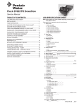
Fleck 4650
Service Manual
TABLE OF CONTENTS
JOB SPECIFICATION SHEET................................................1
INSTALLATION AND START-UP PROCEDURE.....................1
CONTROL VALVE DRIVE ASSEMBLY...................................2
CONTROL DRIVE ASSEMBLY FOR CLOCK.........................3
BYPASS VALVE ASSEMBLY..................................................4
WATER CONDITIONER FLOW DIAGRAMS..........................5
SERVICE INSTRUCTIONS.....................................................7
TROUBLESHOOTING............................................................9
SERVICE ASSEMBLY.............................................................10
INSTALLATION AND START-UP
PROCEDURE
The water softener should be installed with the inlet, outlet and
drain connections made in accordance with manufacturer’s
recommendations and to meet applicable plumbing codes.
Red Time
Set Button
Manual
Regeneration
Knob
24 GR, Gear
Skipper Wheel
(Shows every
other day
regeneration)
JOB SPECIFICATION SHEET
Job Number:_ _______________________________________
Model Number:_ _____________________________________
Water Test: _________________________________________
Capacity Per Unit:_________ Max._________ Per Regeneration
Mineral Tank Size Diameter:______ Height:________________
Brine Tank Size and Salt Setting per Regeneration:__________
1. Type of Timer:
A."L"
B.7 Day
C.12 Day
2. Day/Time of Regeneration:__________________
3. Drain Line Flow Control:____________________ gpm
4. Brine Refill Rate:_ _________________________ gpm
5. Injector Size#: ____________________________
Time of Day
Arrow
Red Pointer
BR61501-4650 Rev A
Figure 1
1. Manually index the softener control into the service position
and let water flow into the resin tank. When the water flow
stops, open a softened water tap until all air is released
from the lines, then close the tap.
Note: The various regeneration positions may be
dialed manually by turning the knob on the
front of the control until the indicator shows
that the softener is in the desired position.
2. Manually index the control to the backwash position and
allow water to flow at the drain for 3 or 4 minutes.
3. Remove back cover plate.
4. Make sure that the salt dosage is set as recommended by
the manufacturer. Manually index the control to the brine fill
position and allow the brine tank to fill to the top of the air
check.
5. Manually index the control to the brine draw position and
allow the control to draw water from the brine tank until it
stops.
6. Plug in the electrical cord and look in the sight hole in the
back of the motor to see that it is running. Set the days that
regeneration is to occur by sliding tabs on skipper wheel
outward to expose trip fingers. Each tab is one day. Finger
at red pointer is tonight. Moving clockwise from red pointer,
extend or retract fingers to obtain the desired regeneration
schedule.
7. Manually advance the control to the beginning of the brine
fill position; and allow the control to return to the service
position automatically.
8. Fill the brine tank with salt.
9. Replace back cover on the control.
10.Make sure that any bypass valving is left in the normal
service position.
BR40261 Rev C
AP10
CONTROL VALVE DRIVE ASSEMBLY
1
27
20
16
15
19
22
13
12
5
18
14
17
26
29
31
1
21
7
8
30
6
9
2
28
25
23
3
10
11
5
4
BR61501-4650 Rev A
Item No.
QTY
Part No.
Description
Item No.
QTY
Part No.
Description
1����������������1������� 15494-01�����������“L” Housing - w/Pin
16��������������2������� 13311����������������Spring - Detent - Skipper Wheel
2����������������1������� 13175����������������Motor Mounting Plate
17��������������1������� 14207����������������Knob Label - Silver
3����������������1������� 18743-1�������������Motor - 120V, 60 Hz, 1/30 rpm
18��������������1������� 14176����������������Valve Position Dial - Standard
19��������������1������� 14381����������������Skipper Wheel Assembly - 12
Day
1������� 18752-1�������������Motor - 100V, 50 Hz, 1/30 rpm
1������� 18824-1�������������Motor - 23V, 50 Hz, 1/30 rpm
1������� 18826-1�������������Motor - 24V, 50 Hz, 1/30 rpm
1������� 19659-1�������������Motor - 24V, 60 Hz, 1/30 rpm
1������� 19660-1�������������Motor - 230V, 60 Hz, 1/30 rpm
1������� 14860����������������Skipper Wheel Assembly - 7 Day
20��������������1������� 13864����������������Skipper Wheel Ring
21��������������2������� 14457����������������Spring - Detent - Main Gear
22��������������1������� 13014����������������Regeneration Pointer
4����������������3������� 11384����������������Screw - Motor Mtg. & Ground
Wire
23��������������1������� 11842����������������Electrical Cord - Standard
5����������������3������� 13296����������������Screw - Component Mounting
24��������������2������� 12681����������������Wire Connector (Not Shown)
6����������������1������� 13017����������������Idler Gear
25��������������1������� 13547����������������Strain Relief
7����������������1������� 13018����������������Idler Pinion
26��������������1������� 15151����������������Screw - Knob
8����������������1������� 13312����������������Spring - Idler
9����������������1������� 13164����������������Drive Gear
27��������������1������� 14331����������������Front Label - Silver on Black 10��������������1������� 40214����������������Screw - Brine Cam
28��������������1������� 12037����������������Washer
11��������������1������� 13170����������������Main Gear & Shaft
29��������������2������� 12473����������������Screw-Drive Mounting
12��������������1������� 19205-01�����������24-Hour Gear Assembly, Silver
30��������������1������� 60514����������������Brine Cam Assembly, 3-18
13��������������1������� 13011����������������Cycle Actuator Gear
14��������������1������� 14177����������������Knob - Manual Regeneration
15��������������4������� 13300����������������Ball - 1/4" Dia.
2 • AP10 Fleck 4650
1������� 60514-01�����������Brine Cam Assembly, 6-36
1������� 60514-02�����������Brine Cam Assembly, Minutes
31��������������1������� 40327����������������Support Bracket (Hot water Only)
CONTROL DRIVE ASSEMBLY FOR
CLOCK
BR61500-4650 Rev A
Item No.
QTY
Part No.
Description
1������������������ 2��������� 13255������������������� Adapter Clip
2������������������ 5��������� 13242������������������� Seal
5��������� 17772������������������� Seal, 4650, HW, Chloramine resistant
3������������������ 1��������� 40319������������������� Valve Body
4������������������ 1��������� 13304������������������� O-ring - Distributor Tube - 1"
1��������� 13304-01�������������� O-ring, -121, 560CD, HW
5������������������ 1��������� 10381������������������� O-ring - Top of Tank
1��������� 10381-01�������������� O-ring, -231, 560CD, HW
6������������������ 1��������� 13361������������������� Stand-Off
7������������������ 4��������� 14241-01�������������� Spacer - Hot Water
4��������� 14241������������������� Spacer - Cold Water
8������������������ 1��������� 13247������������������� Piston - Standard
9������������������ 1��������� 10696������������������� Piston Pin
10���������������� 1��������� 13001������������������� Piston Rod Assembly
11���������������� 1��������� 12953������������������� Piston Retainer
12���������������� 1��������� 61411������������������� End Plug Assembly, Brass - Hot
Water
1��������� 13446������������������� End Plug Assembly, Std., White Cold Water
13���������������� 1��������� 13387������������������� Screw - Injector Mounting
14���������������� 1��������� 13315������������������� Screw - Injector Mounting
15���������������� 2��������� 19228������������������� Adapter Coupling
16���������������� 4��������� 13305������������������� O-ring - Adapter Coupling
17���������������2-4������� 13314������������������� Screw - Adapter Coupling
18���������������� 1��������� 12638������������������� O-ring - Drain
19���������������� 2��������� 13301������������������� O-ring - Injector
2��������� 13301-01�������������� O-ring, -011, 560CD, HW
20���������������� 2��������� 13302-01�������������� O-ring - Brine Spacer - Hot Water
1��������� 12638-01�������������� O-ring, -013, 560CD, Injector, HW
2��������� 13302������������������� O-ring - Brine Spacer - Cold Water
21���������������� 1��������� 13303������������������� O-ring - Injector Cover
1��������� 13303-01�������������� O-ring, -021, 560CD, HW
22���������������� 1��������� 13163������������������� Injector Body
23���������������� 1��������� 10225-xx�������������� Injector Nozzle - Hot Water
1��������� 10913-xx�������������� Injector Nozzle - Cold Water
Item No.
QTY
Part No.
Description
24���������������� 1��������� 10226-xx�������������� Injector Throat - Specify Size - Hot
Water
1��������� 10914-xx�������������� Injector Throat - Specify Size - Cold
Water
25���������������� 1��������� 10227������������������� Injector Screen
26���������������� 1��������� 13166������������������� Injector Cover
27���������������� 1��������� 13172-03�������������� Brine Valve Stem Assembly - Hot
Water
1��������� 13172-02�������������� Brine Valve Stem Assembly - Cold
Water
29���������������� 1��������� 13165������������������� Brine Valve Cap
30���������������� 1��������� 13167������������������� Brine Valve Spacer
31���������������� 1��������� 12550-01�������������� Quad Ring - Hot Water
1��������� 12550������������������� Quad Ring - Cold Water
32���������������� 1��������� 11973������������������� Spring - Brine Valve
33���������������� 1��������� 16098������������������� Washer - Brine Valve
34���������������� 1��������� 11981-01�������������� Retaining Ring
35���������������� 1��������� 10329������������������� BLFC Fitting Nut
36���������������� 1��������� 10330������������������� BLFC Ferrule
37���������������� 1��������� 10332������������������� BLFC Tube Insert
38���������������� 1�������������������������������������� BLFC Button - Specify Size
39���������������� 1��������� 12977������������������� O-ring - BLFC
1��������� 12977-01�������������� O-ring, -015, 560CD, HW
40���������������� 1��������� 13245������������������� BLFC Button Retainer
41���������������� 1��������� 13244������������������� BLFC Fitting
42���������������� 1�������������������������������������� DLFC Button - Specify Size
43���������������� 1��������� 13173������������������� DLFC Button Retainer
44���������������� 1��������� 12767������������������� Screen - Brine Valve
45���������������� 1��������� 15348������������������� O-ring - DLFC (not shown)
46���������������� 1��������� 13497������������������� Air Disperser
47���������������� 1��������� 13546������������������� End Plug Retainer
1��������� 40324������������������� End Plug Retainer, Hot Water
48���������������� 3��������� 12112������������������� Screw
49���������������� 1��������� 13363������������������� Washer
50���������������� 1��������� 13296������������������� Screw
51���������������� 1��������� 13398������������������� Yoke, Brass, 1" NPT
1��������� 13708������������������� Yoke, Brass, 3/4" NPT
Fleck 4650 AP10 • 3
BYPASS VALVE ASSEMBLY
60040SS Rev T
60041SS Rev U
Item No.
QTY
Part No.
Description
1����������������1������� 40614����������������Bypass Body, 3/4"
�������� 40634����������������Bypass Body, 1", SS
2����������������1������� 14105����������������Seal, Bypass, 560CD
3����������������1������� 11972����������������Plug, Bypass
4����������������1������� 11978����������������Side Cover
5����������������1������� 13604-03�����������Label
6����������������8������� 15727����������������Screw
7����������������1������� 11986����������������Side Cover
8����������������1������� 11979����������������Lever, Bypass
9����������������1������� 11989����������������Screw, Hex Head, 1/4-14
10��������������1������� 60040SS�����������Bypass Valve, 5600, 3/4" NPT
Blk Grip Lever, SS
�������� 60041SS�����������Bypass Valve, 5600, 1" NPT Blk
Grip Lever, SS
4 • AP10 Fleck 4650
WATER CONDITIONER FLOW
DIAGRAMS
1 Service Position
3 Backwash Position (10 Minutes)
Hard water enters the unit at the valve inlet - flows around the
lower piston groove - thru the passage to the top of tank - down
thru the resin and enters the distributor as conditioned water.
The conditioned water flows up thru the center tube to the
valve outlet.
Hard water enters the unit at the valve inlet - flows around
the lower piston groove and lower piston land - down thru the
center tube and out the distributor - up thru the resin - thru the
top of tank passage - around the upper piston groove and out
the drain line.
2 Preliminary Rinse Position (5 Minutes)
4 Brine Position (First Portion of 50 Minute Fixed Cycle)
Hard water enters the unit at the valve inlet - flows around
the lower piston groove - down thru the top of tank passage
- downward thru the resin - up the distributor tube - thru the
center hole in the piston - over the top edge of the piston and
out the drain line.
Hard water enters the unit at the valve inlet - flows around the
lower piston groove - thru the injector nozzle and orifice to
draw brine from the brine tank. The brine flows down thru the
resin - into the distributor - up thru the center tube - thru the
center hole in the piston and out the drain line.
Fleck 4650 AP10 • 5
WATER CONDITIONER FLOW
DIAGRAMS continued
5 Slow Rinse Position
(Last Portion of 50 Minute Fixed Cycle)
After all the brine has been drawn from the brine tank, hard
water continues to enter thru the valve inlet - flows around the
lower piston groove - thru the nozzle and orifice - down thru the
resin and into the distributor - up thru the center tube - thru the
center hole in the piston and out the drain line.
6 Second Backwash Position (10 Minutes)
Hard water enters the unit at the valve inlet - flows around
the lower piston groove and lower piston land - down thru the
center tube and out the distributor - up thru the resin - thru the
top of tank passage - around the upper piston groove and out
the drain line.
6 • AP10 Fleck 4650
7 Settling Rinse Position (5 Minutes)
Hard water enters the unit at the valve inlet - flows around
the lower piston groove - down thru the top of tank passage
- downward thru the resin - up the distributor tube - thru the
center hole in the piston - over the top edge of the piston and
out the drain line.
8 Brine Tank Fill Position
(4 to 24 Minutes Adjustable Cycle)
Hard water enters the unit at the valve inlet - flows around the
lower piston groove - thru the injector throat - thru the brine
valve and flow control to fill the brine tank. Hard water also
flows around the lower piston groove - thru the passage to
the top of tank - down thru the resin and enters the distributor
as conditioned water. The conditioned water flows up thru the
center tube to the valve outlet.
SERVICE INSTRUCTIONS
A. TO REMOVE TIME BRINE VALVE, INJECTORS, AND
SCREEN
1. Unplug electrical cord from outlet.
2. Turn off water supply to conditioner:
a. If the conditioner installation has a “three valve”
bypass system, first open the valve in the bypass
line, then close the valves at the conditioner inlet
and outlet.
b. If the conditioner has an integral bypass valve, put
it in the bypass position.
c. If there is only a shut-off valve near the conditioner
inlet, close it.
3. Relieve water pressure in the conditioner by putting the
control in the backwash position momentarily. Return
the control to the service position.
4. Disconnect brine tube and drain line connections at the
injector body.
5. Remove the two injector body mounting screws. The
injector and brine module can now be removed from
the control valve. Remove and discard valve body
O-rings.
6. To replace brine valve:
a. Pull brine valve from injector body, also remove and
discard O-ring at bottom of brine valve hole.
b. Apply silicone lubricant to new O-ring and reinstall
at bottom of brine valve hole.
c. Apply silicone lubricant to O-ring on new valve
assembly and press into brine valve hole, shoulder
on bushing should be flush with injector body.
7. To replace injectors and screen:
a. Remove injector cap and screen, discard O-ring.
Unscrew injector nozzle and throat from injector
body.
b. Screw in new injector throat and nozzle. Be sure
they are seated tightly. Install a new screen.
c. Apply silicone lubricant to new O-ring and install
around oval extension on injector cap.
8. Apply silicone lubricant to three new O-rings and install
over three bosses on injector body.
9. Insert screws with washers through injector cap and
injector. Place this assembly through hole in timer
housing and into mating holes in the valve body.
Tighten screws. Be sure to reinstall brass spacers with
injector on Model 4600 valve.
10. Reconnect brine tube and drain line.
11. Return bypass or inlet valving to normal service
position. Water pressure should now be applied to the
conditioner, and any bypass line shut off.
12. Check for leaks at all seal areas. Check drain seal with
the control in the backwash position.
13. Plug electrical cord into outlet.
14. Set time of day and cycle the control valve manually to
ensure proper function. Make sure the control valve is
returned to the service position.
15. Make sure there is enough brine in the brine tank.
16. Rotate program wheel counterclockwise until it stops at
regeneration position.
17. Start regeneration cycle manually if water is hard.
B. TO REPLACE TIMER
1. Unplug electrical cord from outlet.
2. Turn off water supply to conditioner:
a. If the conditioner installation has a “three valve”
bypass system, first open the valve in the bypass
line, then close the valves at the conditioner inlet
and outlet.
b. If the conditioner has an integral bypass valve, put
it in the bypass position.
c. If there is only a shut-off valve near the conditioner
inlet, close it.
3. Relieve water pressure in the conditioner by putting the
control in the backwash position momentarily. Return
the control to the service position.
4. Remove the control valve back cover.
5. Remove screw and washer at drive yoke. Remove
timer mounting screws. The entire timer assembly will
now lift off easily.
6. Put new timer on top of valve. Be sure drive pin on
main gear engages slot in drive yoke (rotate control
knob if necessary).
7. Replace timer mounting screws. Replace screw and
washer at drive yoke.
8. Return bypass or inlet valving to normal service
position. Water pressure should now be applied to the
conditioner, and any bypass line shut off.
9. Plug electrical cord into outlet.
10. Set time of day, program wheel, and salt usage. Cycle
the control valve manually to ensure proper function.
Make sure the control valve is returned to the service
position.
11. Replace the control valve back cover. Be sure
grommet at cable hole is in place.
12. Make sure there is enough brine in the brine tank.
13. Rotate program wheel counterclockwise until it stops at
regeneration position.
14. Start regeneration cycle manually if water is hard.
Fleck 4650 AP10 • 7
SERVICE INSTRUCTIONS continued
C. TO REPLACE PISTON ASSEMBLY
1. Unplug electrical cord from outlet.
2. Turn off water supply to conditioner:
a. If the conditioner installation has a “three valve”
bypass system, first open the valve in the bypass
line, then close the valves at the conditioner inlet
and outlet.
b. If the conditioner has an integral bypass valve, put
it in the bypass position.
c. If there is only a shut-off valve near the conditioner
inlet, close it.
3. Relieve water pressure in the conditioner by putting the
control in the backwash position momentarily. Return
the control to the service position.
4. Remove the control valve back cover.
5. Remove screw and washer at drive yoke. Remove
timer mounting screws. The entire timer assembly will
now lift off easily. Remove end plug retainer plate.
6. Pull upward on end of piston yoke until assembly is out
of valve.
7. Inspect the inside of the valve to make sure that all
spacers and seals are in place, and that there is no
foreign matter that would interfere with the valve
operation.
8. Take new piston assembly as furnished and push
piston into valve by means of the end plug. Twist yoke
carefully in a clockwise direction to properly align it with
drive gear. Replace end plug retainer plate.
9. Place timer on top of valve. Be sure drive pin on main
gear engages slot in drive yoke. Rotate control knob if
necessary.
10. Replace timer mounting screws. Replace screw and
washer at drive yoke.
11. Return bypass or inlet valving to normal service
position. Water pressure should now be applied to the
conditioner, and any bypass line shut off.
12. Plug electrical cord into outlet.
13. Set time of day. Cycle the control valve manually to
ensure proper function. Make sure the control valve is
returned to the service position.
14. Replace the control valve back cover. Be sure
grommet at cable hole is in place.
15. Make sure there is enough brine in the brine tank.
16. Rotate program wheel counterclockwise until it stops at
regeneration position.
17. Start regeneration cycle manually if water is hard.
8 • AP10 Fleck 4650
D. TO REPLACE SEALS AND SPACERS
1. Unplug electrical cord from outlet.
2. Turn off water supply to conditioner:
a. If the conditioner installation has a “three valve”
bypass system, first open the valve in the bypass
line, then close the valves at the conditioner inlet
and outlet.
b. If the conditioner has an integral bypass valve, put
it in the bypass position.
c. If there is only a shut-off valve near the conditioner
inlet, close it.
3. Relieve water pressure in the conditioner by putting the
control in the backwash position momentarily. Return
the control to the service position.
4. Remove the control valve back cover.
5. Remove screw and washer at drive yoke. Remove
timer mounting screws. The entire timer assembly will
now lift off easily. Remove end plug retainer plate.
6. Pull upward on end of piston rod yoke until assembly
is out of valve. Remove and replace seats and spacers
with fingers.
TROUBLESHOOTING
Problem
Possible Cause
Solution
Softener fails to regenerate
Electrical service to unit has been interrupted.
Ensure permanent electrical service (check fuse, plug,
pull chain or switch).
Timer is defective.
Replace timer.
Power failure
Reset time of day.
Bypass valve is open.
Close bypass valve.
No salt in brine tank.
Add salt to brine tank and maintain salt level above water
level.
Injectors or screen plugged.
Replace injectors and screen.
Insufficient water flowing into brine tank.
Check brine tank fill time and clean brine line flow control
if plugged.
Hot water tank hardness.
Repeated flushings of the hot water tank is required.
Leak at distributor tube.
Make sure distributor tube is not cracked. Check O-ring
and tube pilot.
Internal valve leak.
Replace seals and spacers and/or piston.
Improper salt setting.
Check salt usage and salt setting.
Excess water in brine tank.
See problem Excessive water in brine tank below.
Iron buildup in line to water conditioner.
Clean line to water conditioner.
Iron buildup in water conditioner.
Clean control and add resin cleaner to resin bed.
Increase frequency of regeneration.
Inlet of control plugged due to foreign material
broken loose from pipes by recient work done on
plumbing system.
Remove piston and clean control.
Loss of resin through drain line
Air in water system.
Ensure that well system has proper air eliminator control.
Check for dry well condition.
Iron in conditioned water
Fouled resin bed.
Check backwash, brine draw and brine tank fill, increase
frequency of regeneration. Increase backwash time.
Excessive water in brine tank
Plugged drain line flow control.
Clean flow control
Salt water in service line
Plugged injector system.
Clean injector and replace screen.
Timer not cycling.
Replace timer.
Foreign material in brine valve.
Clean or replace brine valve.
Foreign material in brine line flow control.
Clean brine line flow control.
Drain line flow control is plugged.
Clean drain line flow control.
Injector is plugged.
Clean or replace injectors.
Injector screen plugged.
Replace screen.
Line pressure is too low.
Increase line pressure. Line pressure must be at least 20
psi at all times.
Internal control leak.
Change seals and spacers and/or piston assembly.
Control cycles continuous
Faulty timer mechanism.
Replace timer.
Drain flows continuously
Foreign material in control.
Remove piston assembly and inspect bore, remove
foreign material and check control in various regeneration
positions.
Internal control leak.
Replace seals and/or piston assembly.
Control valve jammed in brine or backwash
position.
Replace seals and/or piston assembly.
Timer motor stopped or jammed.
Replace timer.
Softener delivers hard water
Unit uses too much salt
Loss of water pressure
Softener fails to draw brine
Fleck 4650 AP10 • 9
SERVICE ASSEMBLY
60102-00��������������������Piston Assembly Cold Water - Softener
60102-10��������������������Piston Assembly Cold Water Feeder/Filter
60102-20��������������������Piston Assembly, Cold Water - Low
Water
60102-031������������������Piston Assembly - Hot Water - Softener
60102-231������������������Piston Assembly, 4650, 560CD CW/HW
- Softener
60125�������������������������Seal Kit - Cold Water
60125-05��������������������Seal Kit - Hot Water
60084-XXXX���������������Injector - Cold Water
See Parts List
***�������������������������������Injector - Hot Water
60032�������������������������Brine Valve - Cold Water
60032-001������������������Brine Valve - Hot Water
60514�������������������������Brine Cam, 3-18
60514-01��������������������Brine Cam, 6-36
60514-02��������������������Brine Cam, Minutes
60510�������������������������Coupling with Clip and Screws
60040�������������������������Bypass, Brass 3/4" NPT - Cold Water
60041�������������������������Bypass, Brass 1" NPT - Hot Water
14860�������������������������Skipper Wheel - 7 Day
14381�������������������������Skipper Wheel - 12 Day
Flow Control Washers
19153�������������������������0.6 gpm
19152�������������������������0.8 gpm
19151�������������������������1.0 gpm
12085�������������������������1.2 gpm
19150�������������������������1.3 gpm
12086�������������������������1.5 gpm
19149�������������������������1.7 gpm
12087�������������������������2.0 gpm
12088�������������������������2.4 gpm
12089�������������������������3.0 gpm
12090�������������������������3.5 gpm
12091�������������������������4.0 gpm
19147�������������������������4.5 gpm
12092�������������������������5.0 gpm
17814�������������������������6.0 gpm
12408�������������������������7.0 gpm
***Hot water injector components are listed separately.
10 • AP10 Fleck 4650
Fleck 4650 AP10 • 11
© 2010 Pentair Residential Filtration, LLC 40261 Rev C
AP10